Ion energy Distribution of Multi-Frequency Capacitively Coupled Plasma
2016-RISE-Poster lI
1. • Principal Investigator: Nicol McGruer
• Graduate Mentors: Tao Wu, William Zhu
Undergraduate/Graduate
Category: Engineering
Degree Level: Undergraduate
Abstract ID# 1451
Resonant Frequency Modeling for MEMS Relays and Switches
Background/ Purpose Resonant Detector Models
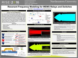
Data/ Results (30 ms)
The next steps include:
• Revising the model to take into account energy loss and
other modes
• Determining how to prevent these phase shifts when the
contact hits
• Converting this system representation into a physical model
for contact representation
• Testing these Devices
• N. Sinha, T. S. Jones, Z. Guo and G. Piazza, "Body-Biased Complementary Logic Implemented
Using AlN Piezoelectric MEMS Switches," in Journal of Microelectromechanical Systems, vol. 21,
no. 2, pp. 484-496, April 2012.doi: 10.1109/JMEMS.2011.2179015
• Yang Lin, Ruonan Liu, Wei-Chang Li and Clark T. C. Nguyen, “Polycide contact interface to
suppress squegging in micromechanical resoswitches,” Technical Digest, The 27th IEEE
International Conference on Micro Electro Mechanical Systems (MEMS 2014), San Francisco,
CA, Jan. 26-30, 2014,
Kasia Gibson | Gibson.ka@husky.neu.edu | Electrical Engineering
Applications
Purpose: Zero Power MEMS Relays
• Internet of Things: reduce size and power (100x) required to maintain a
network of sensors
• Remote threat
• Natural fire detection
• Household fire alarms
• Vehicular pollutant monitoring
Zero Power Sensors have the potential to transform Big Data. Currently,
active electronics are consuming power (through wiring) continuously in
order to pick up signals. This power-consuming method is not financially
sustainable or environmentally sound. Sensor technologies could remedy
this by continuously and passively monitoring the environment by “waking-
up” an electronic signal upon detection of a specific trigger signature
without using any power until environmental variables trigger wake-up.
This poster focuses on Phase 3 of this procedure, the MEMS Resonant
Detector Switch, which is responsible for taking in an amplified radio
signal and detecting it at the resonant frequency. The resonant detector
would switch on at the resonant frequency.
Figure 5: Position vs Time (Cantilever Output)
Figure 4: (a) Force vs Time Output, (b) Zoomed graph of 1st contact peak
• When the driving frequency is close to resonance, the amplitude of
the displacement grows continuously
• As contact is hit, the oscillation becomes out-of-phase, making the
system non-linear
• Displacement decreases since the driving signal decreases
Figure 3: (a) Frequency not at resonance (Position vs time), (b) Zoomed
Process: Zero Power Sensors
Focus: Phase 3
Discussion
Acknowledgements
References
When the frequency is not in resonance, it does not oscillate enough, meaning it
cannot hit the contact.
The net force is plotted against time to see the force as the contact is touched.
The small graph is a zoomed scale of the first peak.
• The simple mass-
spring is an
accurate
equivalence of the
resonant switch
being simulated.
• Forces:
- Contact
- Electrostatic
- Damping
- SpringModel 1: Cantilever System
Figure 2: Equivalent SystemsFigure 1: Cantilever Mechanical System
Tip movement (x)
stretches the spring,
causing damping and
tip has an associated
mass (inertia)
Cantilever behaves as a linear
spring
𝑭 = 𝒌 𝟐 𝒙
Energy Loss due to
air damping
𝑭 = 𝒃𝒗
𝑭 = 𝒌 𝟏(𝒙 𝒔𝒂𝒕 + 𝒈 𝟎)
𝑭 =
𝜺𝑨𝑽 𝟐
𝟐𝒈 𝟎
𝟐
A radio signal (18µV) goes to
an antenna.
When the correct radio
signal is detected, it is
amplified (18mV).
As force pulls on the beam,
the signal goes in to make it
oscillate (“wake-up”).
A Low power threshold switch
is used to avoid leakage
currents to achieve a very
small equivalent sub-threshold
swing.