1. Lorentz Symmetry Breaking: Monopole Lensing
Department of Physics Astronomy, and Geophysics, Connecticut College
Jianbin Guan ‘19 (Jguan@conncoll.edu) Instructor: Michael Seifert
Background
Special Relativity:
i. The laws of physics are identical in all inertial
reference frames
ii. The speed of light in a vacuum is the same for all
inertial reference frames (Lorentz Symmetry)
Tensor Field: Generalization of a vector field or
scalar field at each point in space. Example: Electric
field, Magnetic field, etc
Monopole: Hypothetical non-constant tensor field
with spherical symmetry
Fermat’s Principle (The Principle of Least Time): The
“shortest” path between two points are the path
which will minimize the travel time
The phenomenon which speed of light varies at each
point in space is an example of Lorenz Symmetry
Breaking
Coupling Parameter: 𝜉 ---“Knob”, it determines how
much influence the tensor field has on the light
bending effect
As 𝜉 increase, light bending effect gets stronger,
and vice versa
Attractive Case (𝜉 > 0): light will bend toward to
the monopole
Repulsive Case (𝜉 <0): light will bend away from
the monopole
Method
Steps to set pp the mathematical model (Mathematica):
1. Polar coordinate----dS
2. Interpolation of monopole profile to get g(r) function
3. Euler-Lagrange Equation
4. Set up the numerical integration
Analysis
Result
Three Hypothesis:
Accuracy and precision goal are too low
Limit of integration is at infinity
Extension of the interpolation function fails
Solutions
Increase accuracy and precision goal
U-Substitution
Extension of g(r)
We recorded where the bump occurs and what the bump
ratios are
Bump Ratio =
𝛼 𝑚𝑎𝑥
𝛼𝑖𝑛𝑓𝑖𝑛𝑖𝑡𝑦
.
Could it be numerical error?
The bump seems to persist!
Repulsive Case
𝜉 Bump
Ratio
(𝛽 𝑚𝑎𝑥, 𝛼max)
-0.001 1.138 (2.4, 3.57 × 10⁻³
)
-0.002 1.138 (2.4, 7.15 × 10⁻³
)
-0.005 1.137 (2.4, 1.79 × 10⁻²
)
-0.01 1.136 (2.4, 3.57 × 10⁻²
)
-0.02 1.136 (2.5, 7.14 × 10⁻²
)
-0.05 1.137 (2.7, 1.79 × 10⁻¹
)
Attractive Case
𝜉 Bump
Ratio
(𝛽 𝑚𝑎𝑥, 𝛼max)
0.001 1.144 (2.3 , 3.59 × 10⁻³
)
0.002 1.133 (2.1, 7.12 × 10⁻³
)
0.005 1.131 (2.3, 1.78 × 10⁻²
)
0.01 1.130 (2.3, 3.56 × 10⁻²
)
0.02 1.129 (2.2, 7.11 × 10⁻²
)
0.05 1.130 (2.0, 1.78 × 10⁻¹
)
Conclusion
Thus far, we have discovered the relationship between the
deflection angle and the impact parameter. More specifically,
we found out that for each value of 𝜉, there is a maximum
impact parameter which will maximize the light bending
effect and the bump ratios are relatively consistent.
The following diagrams illustrate the light bending trajectories:
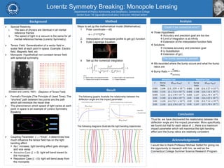
The following graphs illustrate the relationship between the
deflection angle and the impact parameter:
Acknowledgement
I would like to thank Professor Michael Seifert for giving me
the opportunity to research with him, as well as the
Connecticut College Summer Science Research Program.