1. AXIAL COMBUSTION ENGINE
GENERATION 11
The Axial Combustion Engine,(“ACE”) for short, is a heat engine that consists of a rotor, with a
rotor shaft, and a casing. The casing houses the Air manifold that routs the compressed air from
the compressor to the engine cavities, the fuel injectors, supplying fuelto the engine cavities, the
spark plugs, to fire each cavity, and the exhaust manifold that routs the exhaust gases out of the
engine. The only moving partis the rotor and its attached shaft.
The rotor has the engine in the center with a 2 stage compressor on each side catching any blow
by from the engine, remixing and recycling it with the intake air, also keeping the pressurized
cavities at a constantpressure. Thecompressor consists of centrifugalair compressor wafers.
The wafers are stacked in series parallel 2 stage to supply a larger volume and pressure, and in
this case weare using 10 (5 on each side) wafers for the compressor. Theengine consists of
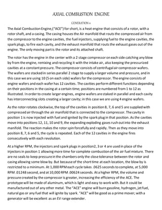
engine wafers and each wafer has 12 cavities. The cavities performdifferent functions depending
on their positions in the casing at a certain time; positions are numbered from1 to 12 as
illustrated. In order to create larger engines, engine wafers arestaked in parallel and each cavity
has interconnecting slots creating a larger cavity; in this case we are using 4 engine wafers.
As the rotor rotates clockwise, the top of the cavities in position 8, 7, 6 and 5 are supplied with
compressed air through the air manifold that is connected to the compressor. Thecavity in
position 1 is now injected with fuel and ignited by the spark plug in that position. As the cavities
move into positions 12, 11, 10 and 9, the expanding exploding gases rush outinto the exhaust
manifold. The reaction makes the rotor spin forcefully and rapidly. Then as they move into
position 8, 7, 6 and 5, the cycle is repeated. Each of the 12 cavities in the engine fires
consecutively with each revolution.
At a higher RPM, the injectors and spark plugs in position2, 3 or 4 are used in place of the
injectors in position 1 allowing more time for complete combustion of the air fuel mixture. There
are no seals to keep pressurein the chambers only the closetolerance between the rotor and
casing allowing some blow by. But becauseof the shorttime at each location, the blow by is
restricted to a minimum. At 1,000 RPMeach cycle takes .0625 seconds to complete, at 5,000
RPM .01248 second, and at10,000 RPM.00624 seconds. Ata higher RPM, the volume and
pressurecreated by the compressor is greater, increasing the efficiency of the ACE. The
prototypewill be made of aluminum, which is light and easy to work with. But it could be
manufactured out of any other metal. The “ACE” engine will burn gasoline, hydrogen, jetfuel,
natural gas or any fuel that will ignite by spark. “ACE” will be good as a prime mover; with a
generator will be excellent as an EV range extender.
2. ..
AXIAL COMBUSTION ENGINE
“ACE” GEN ELEVEN MODE OFOPERATION
The “ACE” engine to operate consist of the motor, fuel supply, fuel pump, fuel management, fuel injector,
battery, ignition system, spark plug, starter motor, and a alternator. The ignition key is turned on; the spark plug
will start to continually be fired by the ignition system in only one of the positions. At start up it will be position
one. The starter switch is engaged the starter motor begin rotation of the rotor; it has to begin rotation before
the fuel can be injected into the chamber, once it reaches a predetermine RPM, fuel is allowed to be injected into
one of the cavities, at start up that will be position one, the fuel injected will mix with the air at that chamber
then it will be ignited by the spark plug creating a self sustained rotation. As the rotor pick up speed by the
combusting gases, the starter motor disengages, the compressor will reach idle speed compression. Fuel and
ignition sparks is provided at a continuous rate to only one of the cavities at a time, no timing is needed; the
cavities will receive the air fuel and ignition spark when it reaches the correct position. The speed and power is
controlled by the fuel management regulating the amount of fuel is injected. At higher RPM the fuel and ignition
spark are switched to one of the other positions to allow for more complete combustion. All other support
equipment and accessories will be attached via one of the PTO shafts. Alternator is attached to the PTO and
keeps the battery charged used for operation of the motor and other electrical accessories. To stop the motor,
simply turn the ignition key switch of, this will stop fuel supply and ignition spark shutting the motor off.
3. -
- Rotor Casing
Complete “ACE”engine
Juan Mesa
Email: jpmesa39@aol.com
Specification:
Engine Length 16.75 in
ShaftLength 28.75 in
Width 16.00 in
Height 18.00 in
Weight 229 lb
Displacement 338.28 Cu in
Output 344 Hp @ 5,000 RPM (256 KW)
Output 688 Hp @ 10,000 RPM (512 KW)
PTO (PowerTake Off) 2EA 1.5” shafts