IRJET- Optimization of Flat Plate Solar Collector with Novel Heat Collect...
082-089_TechAward_LaRosh for Web
1. A S H R A E J O U R N A L ashrae.org SEPTEM BER 201582
BUILDING AT A GLANCE
Jason LaRosh, P.E., is a mechanical engineer at Angus-Young Associates, Inc., in Janesville, Wis.
FIRST PLACE
PUBLIC ASSEMBLY, EXISTING
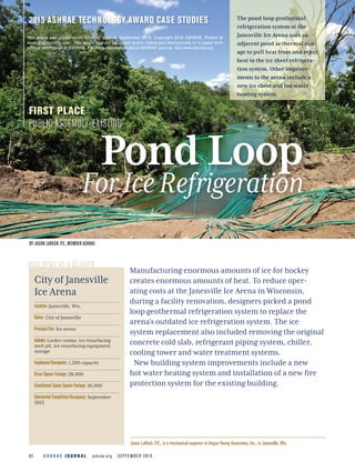
2015 ASHRAE TECHNOLOGY AWARD CASE STUDIES The pond loop geothermal
refrigeration system at the
Janesville Ice Arena uses an
adjacent pond as thermal stor-
age to pull heat from and reject
heat to the ice sheet refrigera-
tion system. Other improve-
ments to the arena include a
new ice sheet and hot water
heating system.
Pond Loop
ForIceRefrigeration
BY JASON LAROSH, P.E., MEMBER ASHRAE
City of Janesville
Ice Arena
Location: Janesville, Wis.
Owner: City of Janesville
Principal Use: Ice arena
Includes:Locker rooms, ice resurfacing
melt pit, ice resurfacing equipment
storage
Employees/Occupants: 1,200 capacity
Gross Square Footage: 28,000
Conditioned Space Square Footage: 26,000
Substantial Completion/Occupancy: September
2012
Manufacturing enormous amounts of ice for hockey
creates enormous amounts of heat. To reduce oper-
ating costs at the Janesville Ice Arena in Wisconsin,
during a facility renovation, designers picked a pond
loop geothermal refrigeration system to replace the
arena’s outdated ice refrigeration system. The ice
system replacement also included removing the original
concrete cold slab, refrigerant piping system, chiller,
cooling tower and water treatment systems.
New building system improvements include a new
hot water heating system and installation of a new fire
protection system for the existing building.
This article was published in ASHRAE Journal, September 2015. Copyright 2015 ASHRAE. Posted at
www.angusyoung.com . This article may not be copied and/or distributed electronically or in paper form
without permission of ASHRAE. For more information about ASHRAE Journal, visit www.ashrae.org.
3. A S H R A E J O U R N A L ashrae.org SEPTEM BER 201584
ABOVE Water-source heat pumps are used for
heat reclaim in the arena.
RIGHT The Janesville Ice Arena’s energy use
intensity dropped 24.1% from 2010 (pre-
renovatiaon) to 2013.
BRANTERICKSON
An additional 2,000 ft2 (186 m2) was added to the exist-
ing 26,000 ft2 (2415 m2) building for new locker rooms,
an ice resurfacing melt pit and resurfacing equipment
storage area. The arena’s seating area is approximately
1,200 people. Administration areas (including offices,
skate rental and warming areas) were not directly a part
of this project.
Energy Efficiency
The net 26,000 ft2 (2415 m2) ice arena includes one
200 ft by 85 ft (61 m by 26 m) regulation ice sheet. The
original ice refrigeration system was installed in 1964
and was at the end of its useful life. It used R-22 refriger-
ant circulated in piping embedded in the rink floor.
The new ice refrigeration system’s pond loop geother-
mal system uses city-owned Lion’s Pond that is adjacent
to the building as thermal storage to pull heat from and
reject heat to the ice sheet refrigeration system. The ice
refrigeration system is made up of three water-source
heat pumps with a cooling capacity of 50 tons (176 kW)
each. The pond is used as a renewable energy source
through the combining of a series of high density poly-
ethylene (HDPE) pipe loops that are sunk to the bottom
of the pond approximately 18 ft (5.4 m) deep. The water-
source heat pumps supply 30% glycol solution at 17°F
(– 8.3°C) to the ice rink.
The heat pumps are designed to operate with a cool-
ing efficiency of approximately 11.0 energy efficiency
ratio (EER) and a heating efficiency coefficient of per-
formance (COP) between 3.4 and 3.8. The geothermal
source side of the system maintains an average tempera-
ture of 70°F (21°F) at peak summer loads.
The system was designed to reclaim as much heat as
possible from the water-source heat pumps and use it to
heat water for the ice sheet underfloor heating system,
the snow melt pit, and the ice resurfacing water preheat
system. The underfloor heating system distributes
tempered water to a bed of sand located beneath the
concrete ice slab and keeps the subfloor above freez-
ing (34°F to 38°F [1.1°C to 3.3°C]) to prevent the ice slab
from cracking or upheaving.
A snow melt pit was added inside to allow the ice
resurfacing equipment a place to unload ice without
exposing the arena and its ice skaters to ambient condi-
tions. It is equipped with radiant piping in its walls and
floors. The snow melt pit is designed to maintain a sump
temperature range of 42°F to 45°F (5.6°C to 7.2°C) and
be capable of melting a full ice resurfacing load within
one hour.
The existing building hot water heating system was
redesigned with a low temperature, condensing hot
water boiler designed to provide 120°F (49°C) heating
hot water to the office areas and to provide auxiliary
heat to the locker rooms. The new low temperature sys-
tem is designed to operate with return water tempera-
tures between 90°F and 100°F (32°C to 38°C), and will
operate with a combustion efficiency of approximately
94%. The previous cast-iron boilers were operating with
a total thermal efficiency closer to 75%.
The new and existing locker rooms use a new energy
recovery ventilator to provide the code mandated ven-
tilation air. The energy recovery ventilator is equipped
with a total energy recovery wheel that preconditions
the ventilation air prior to heating or cooling the air-
stream. The energy wheel operates with an effective-
ness of 0.65, with a capacity of 72 MBtu (76 MJ) in design
summer conditions (89°F dry bulb, 77°F wet bulb [32°C
dry bulb, 25°C wet bulb]) and 115 MBtu (121 MJ) in design
winter conditions (– 10°F [– 23°C] dry bulb). Energy
recovered from the wheel reduces the load on the gas-
fired heat exchanger and the DX cooling components of
the rooftop unit serving the locker rooms.
2015 ASHRAE TECHNOLOGY AWARD CASE STUDIES
5. A S H R A E J O U R N A L ashrae.org SEPTEM BER 201586
Indoor Air Quality and Thermal Comfort
The indoor air quality of the existing and new locker
rooms was improved through implementation of a
new packaged rooftop energy recovery unit. It pro-
vides 0.5 cfm (0.24 L/s) of fresh air along with an
equal amount of exhaust, meeting ASHRAE Standard
62.1-2007 requirements for minimum exhaust rates.
The unit is equipped with a mechanical dehumidifica-
tion cycle that allows it to control space humidity levels
and increase occupant comfort in the locker rooms.
Ventilation for the existing offices, auxiliary spaces and
the rink area were not modified during this project.
The pond loop geothermal system eliminates the need
for water treatment chemicals required for a cooling
tower of a conventional ice rink refrigeration system.
Removing chemical treatment reduces the potential of
fumes in the building and eliminates the exhaust sys-
tems required to provide adequate ventilation.
Operation and Maintenance
The project not requiring an evaporative cooling tower
also means the cost of water and water treatment is
reduced or eliminated.
The system was designed to use a 30% glycol brine
solution in lieu of a direct refrigerant system that was
existing in the building. The indirect system reduces the
amount of refrigerant in the system, which will reduce
replacement cost and the potential for refrigerant leaks.
The water-source heat pump uses scroll compressors
typical to the HVAC industry that can be serviced by local
HVAC technicians already serving the building, elimi-
nating the need for the City of Janesville to enter into an
additional contract with a local refrigeration contractor.
Cost Effectiveness
Implementation of the geothermal pond loop system
cost the City of Janesville an additional $119,100 upfront
compared to a conventional ammonia ice refrigera-
tion system at the time of bidding; the cost savings to
the City of Janesville was expected to be seen in yearly
Upgrades and improvements to the building energy
systems resulted in an annual natural gas energy sav-
ings of 33.5% from 2010 to 2013 (Table1). The electrical
energy use increased by 5.5% from 2010 to 2013. The first
source for the increased electrical use is the 2,000 ft2
(186 m2) addition and the subsequent lighting and
air-conditioning cost directly related to the new locker
rooms. The second source was the increased lighting to
the ice sheet required by the Janesville Jets, the junior
hockey league team that plays there, and its parent
organization, the North American Hockey League. These
improvements increased the installed wattage by 13,550
W or 47,425 kWh, based on 3,500 average annual operat-
ing hours. The overall facility energy use intensity (EUI)
was reduced from 234.6 kBtu/ft2·yr (2664 MJ/m2·yr) in
2010 to 178 kBtu/ft2·yr (2121 MJ/m2·yr) in 2013, a reduc-
tion of 24.1%.
Innovation
Using a pond loop geothermal system with a water-
source heat pump is a common application in North
America. The uniqueness of using a geothermal system
as an ice plant refrigeration system is that the system
will reject heat to the pond throughout the year and
depends on the large mass of the pond to dissipate that
heat to the atmosphere. The system design eliminates
the risk of developing an imbalance in temperatures
that could arise in a traditional vertical or horizontal
borefield. The imbalance in loads requires that tradi-
tional vertical and horizontal geothermal bore field sys-
tems be oversized to handle the capacity of the ice plant
system making it uneconomical to install. The Lion’s
Pond is a 12 acre (4.9 ha) lake with a consistent depth of
15 ft (4.6 m). The large volume diminishes the impact of
the rejected heat from the water-source heat pumps and
allows for constant condenser water temperatures.
The condenser water system is designed to use heat
rejected from the heat pumps and transfers that energy
to other systems such as ice resurfacing machine water
preheat, ice melt pit and underslab heating systems.
The snow melt pit consists of 8 in. (203 mm) concrete
walls with 1,300 ft (396 m) of 0.75 in. (19 mm) hot water
piping spaced 6 in. (152 mm) on center in both pit walls
and floor slab. The pit uses heat rejected from the heat
pumps to provide hot water that flows through the con-
tinuous loop of high density polyethylene pipe, heating
the concrete walls and floor of the pit.
TABLE 1 Energy use comparison.
YEAR NATURAL GAS USE (THERMS) ELECTRICAL ENERGY USE (KWH)
2010 37,251 696,000
2013 24,784 734,600
Percent
Change – 33.5 +5.5
2015 ASHRAE TECHNOLOGY AWARD CASE STUDIES
7. a non-ozone depleting refrigerant. The geothermal heat
pump system transfers energy to and from the pond with-
out burning fossil fuels. The EPA recognizes geothermal
heat exchange as an effective way of reducing carbon
monoxide, carbon dioxide and other greenhouse gases.
The geothermal heat pump system’s ability to recover
heat rejected from the ice-making system reduces the
heating load on the building hot water and domestic hot
water heating systems, which lowers the runtime of the
condensing boilers and reduces carbon emissions. The
increased combustion efficiency of the new condens-
ing boilers will also reduce the overall carbon emissions
produced by the building hot water heating system.
Not needing a cooling tower and water treatment elim-
inates or reduces the risk of chemicals introduced to the
environment, sanitary and storm water systems.
PHOTO 1 Installation of ice slab chilled glycol water
piping.
PHOTO 2 Completed ice slab.
maintenance, annual energy use
and water use savings. The total
annual energy savings was calcu-
lated based on existing energy use
data and maintenance contracts
and estimated to be approximately
$15,625. The resulting simple pay-
back is 7.6 years.
Environmental Impact
The water-source heat pumps use
R-410A, which does not contain bro-
mine or chlorine and is considered
2015 ASHRAE TECHNOLOGY AWARD CASE STUDIES
Advertisement formerly in this space.