The document provides instructions for getting started with a product, including reading a tutorial, getting support, and safety precautions. It also introduces Freenove which provides open source electronic products and services worldwide and is committed to assisting customers in education. The document is released under a Creative Commons license and Freenove brand and logo cannot be used without permission.

![support@freenove.com █
15
Chapter 2 LED Bar Graph
█ www.freenove.com
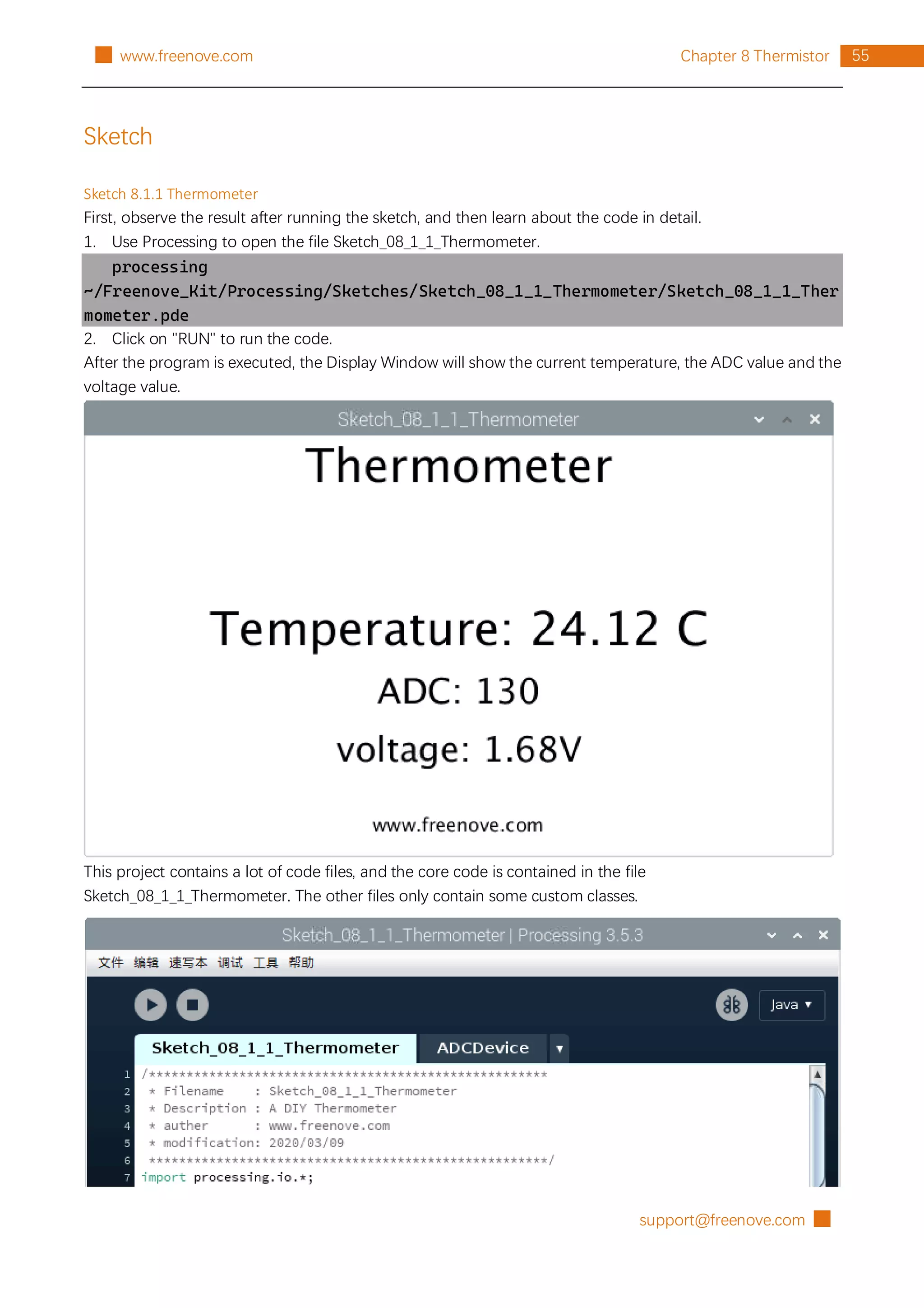
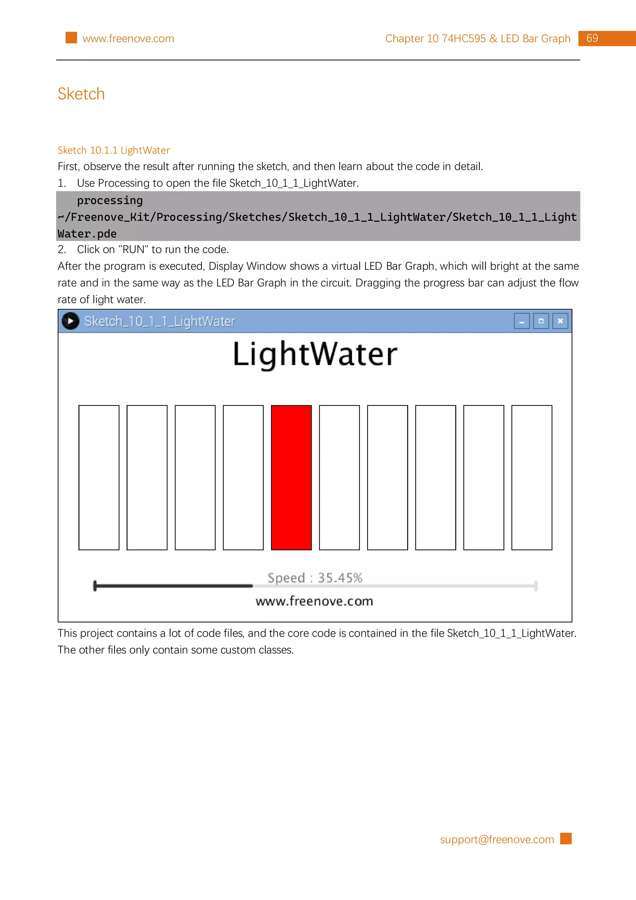
Sketch
Sketch 2.1.1 FollowLight
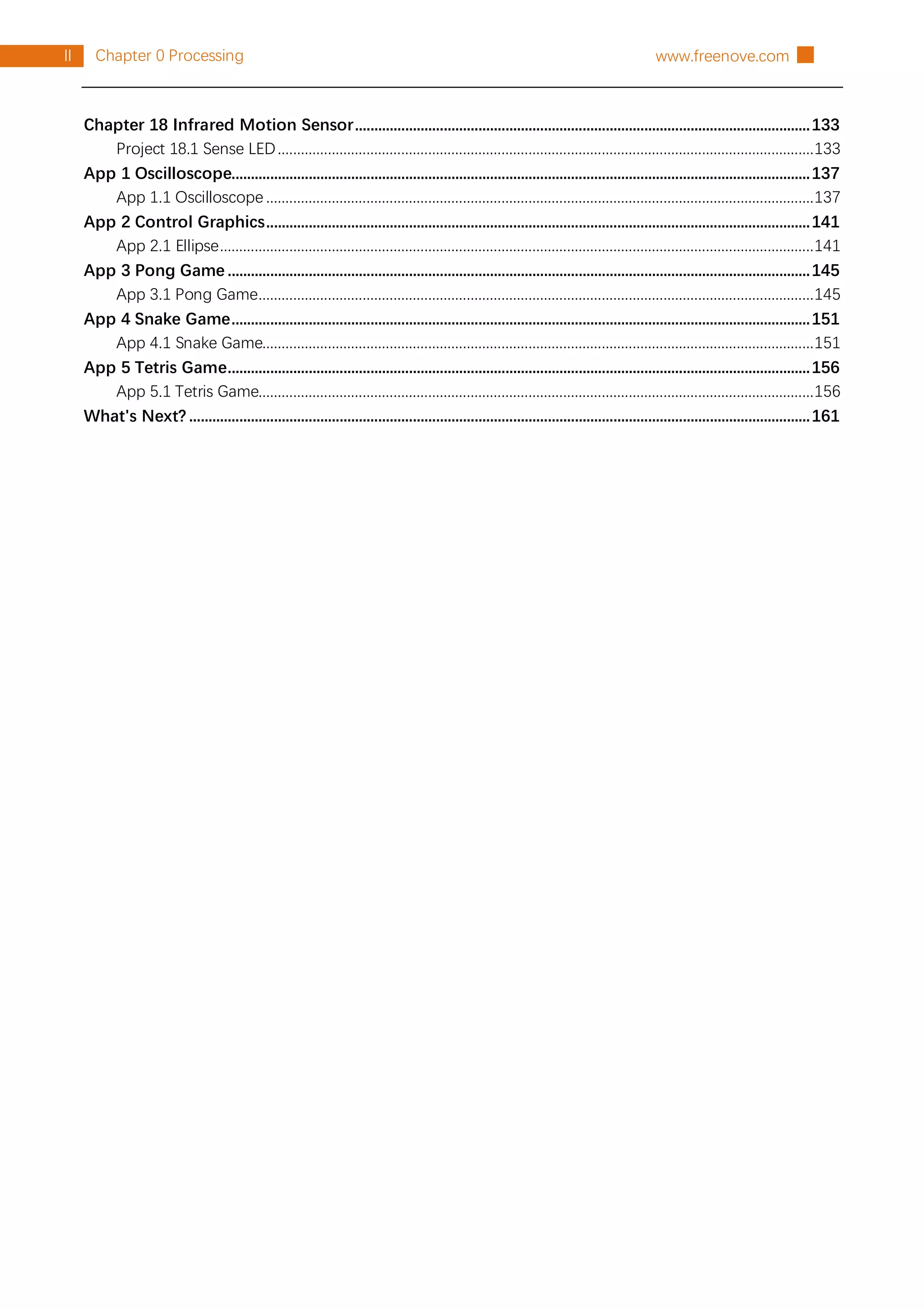
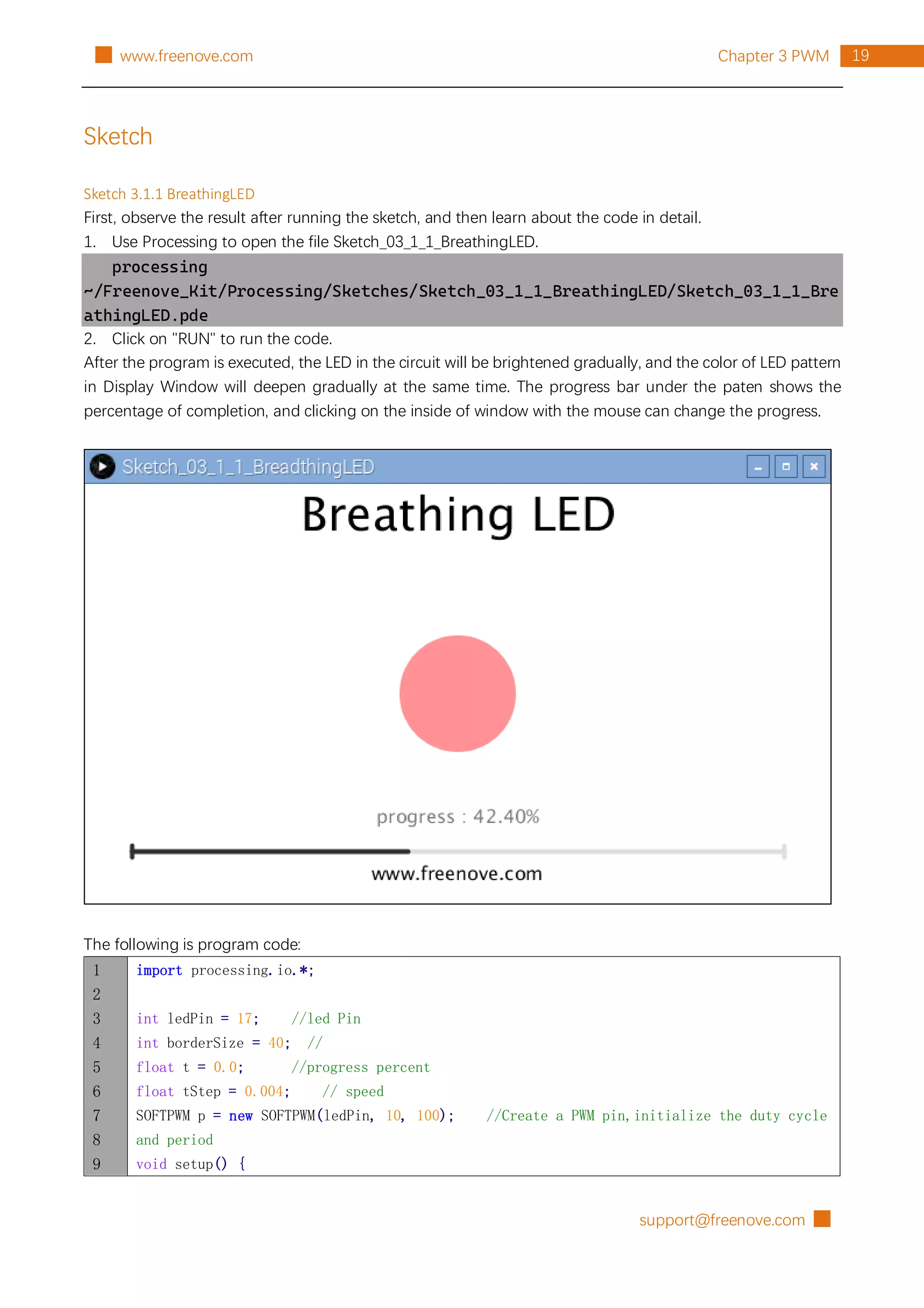
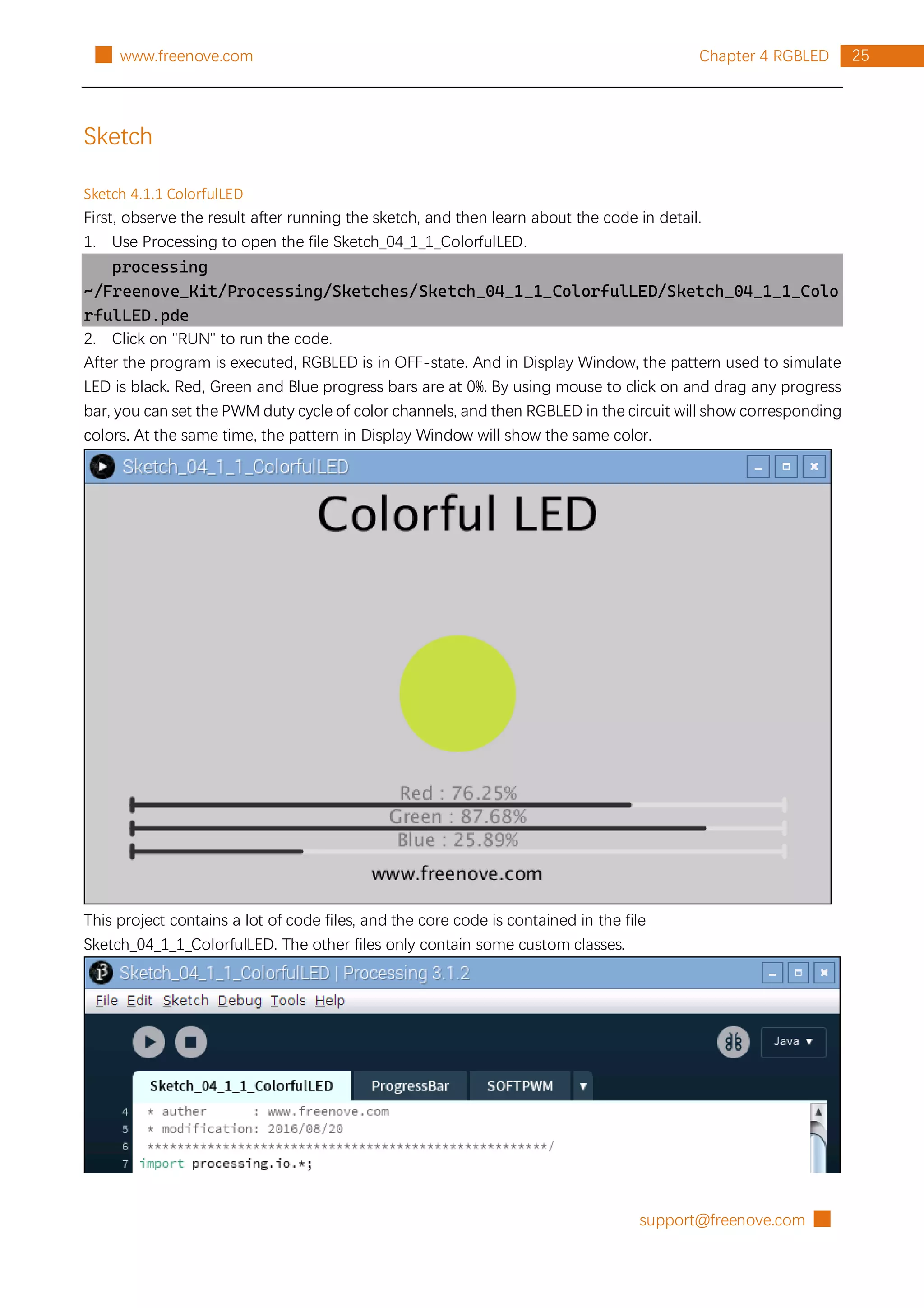
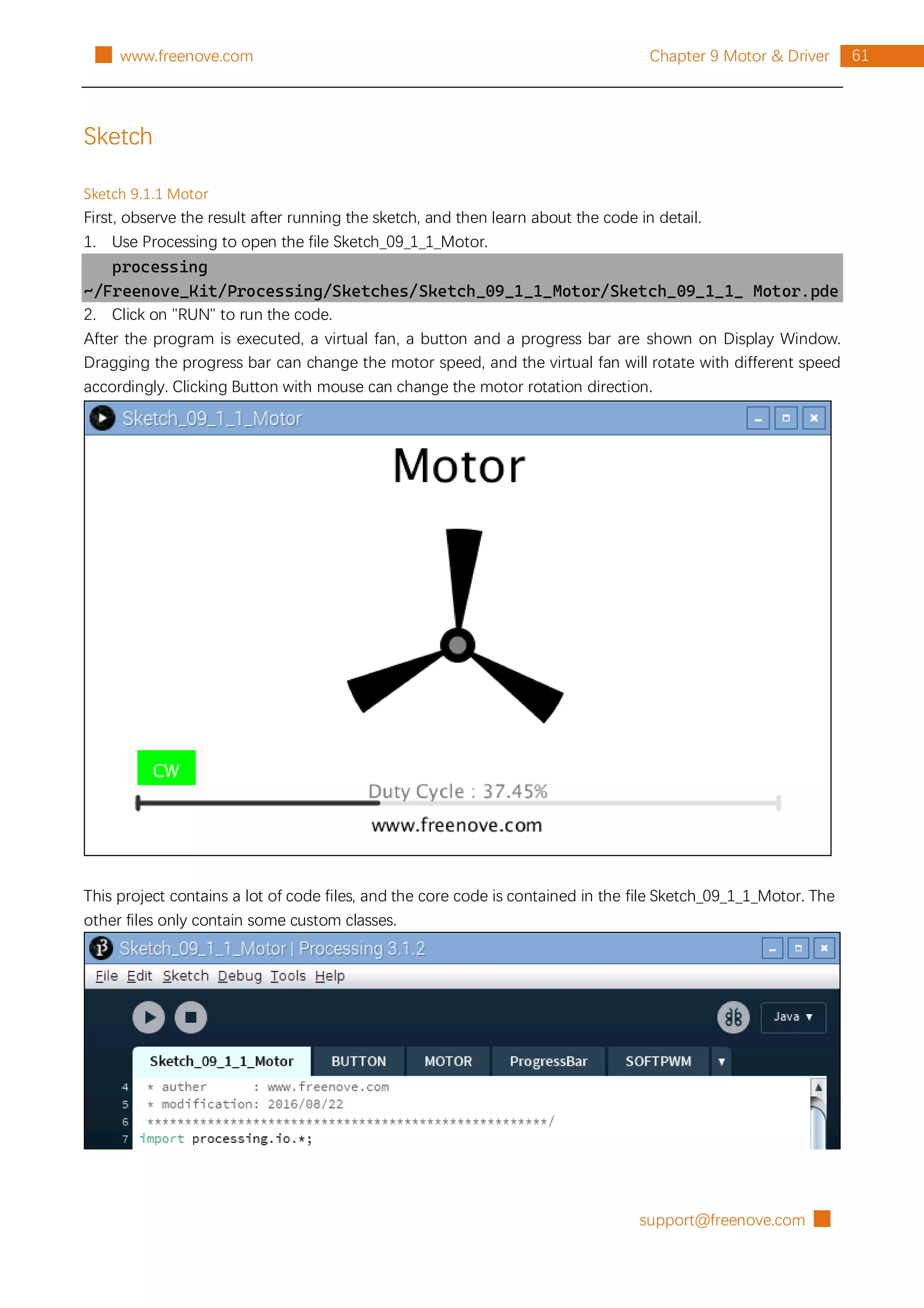
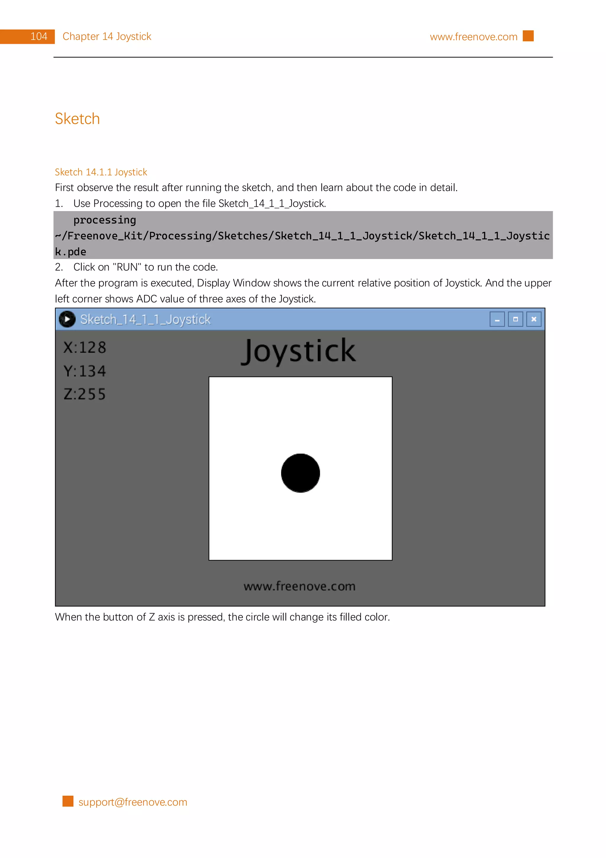
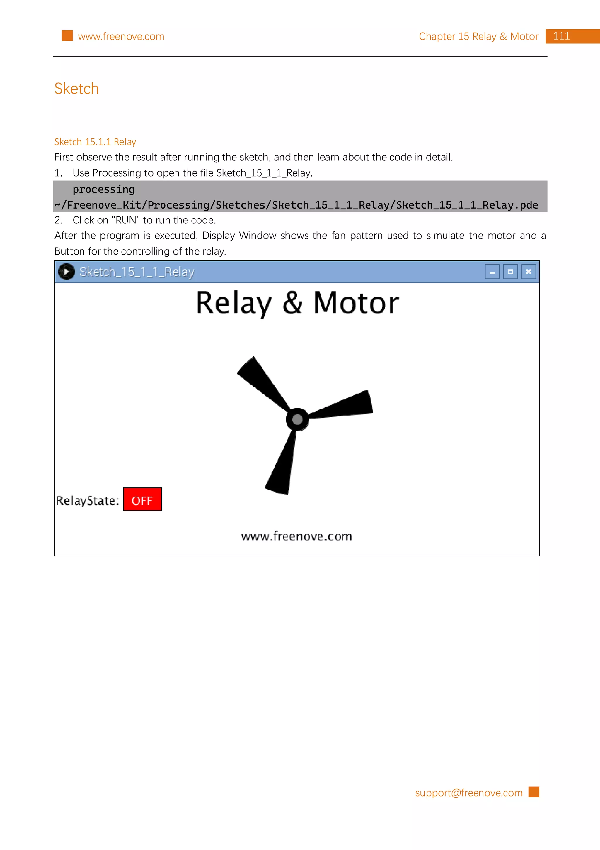
First, observe the result after running the sketch, and then learn about the code in detail.
1. Use Processing to open the file Sketch_02_1_1_FollowLight.
processing
~/Freenove_Kit/Processing/Sketches/Sketch_02_1_1_FollowLight/Sketch_02_1_1_FollowLi
ght.pde
2. Click on "RUN" to run the code.
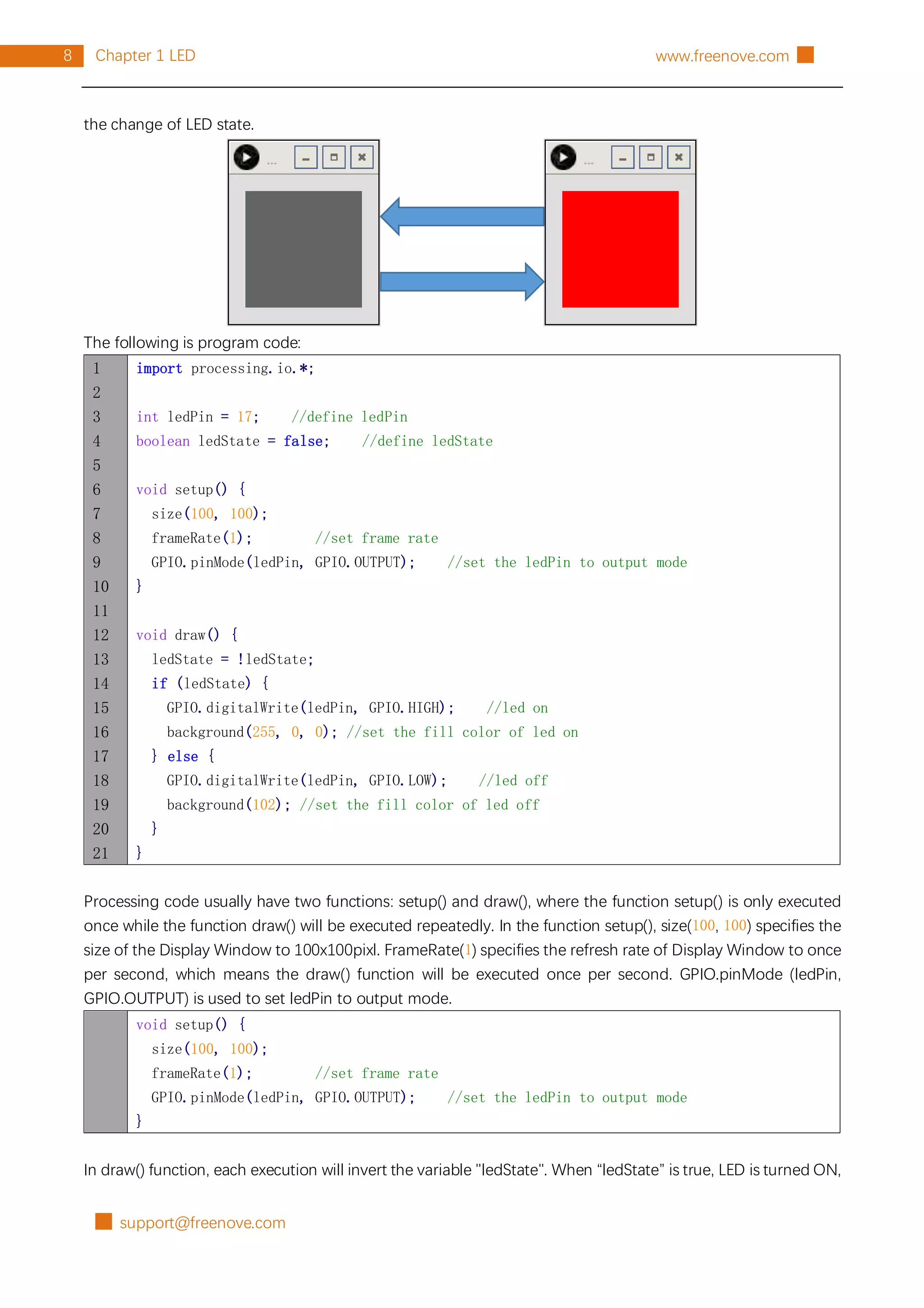
After the program is executed, slide the mouse in the Display Window, then the state of LED Bar Graph will
be changed, as shown below.
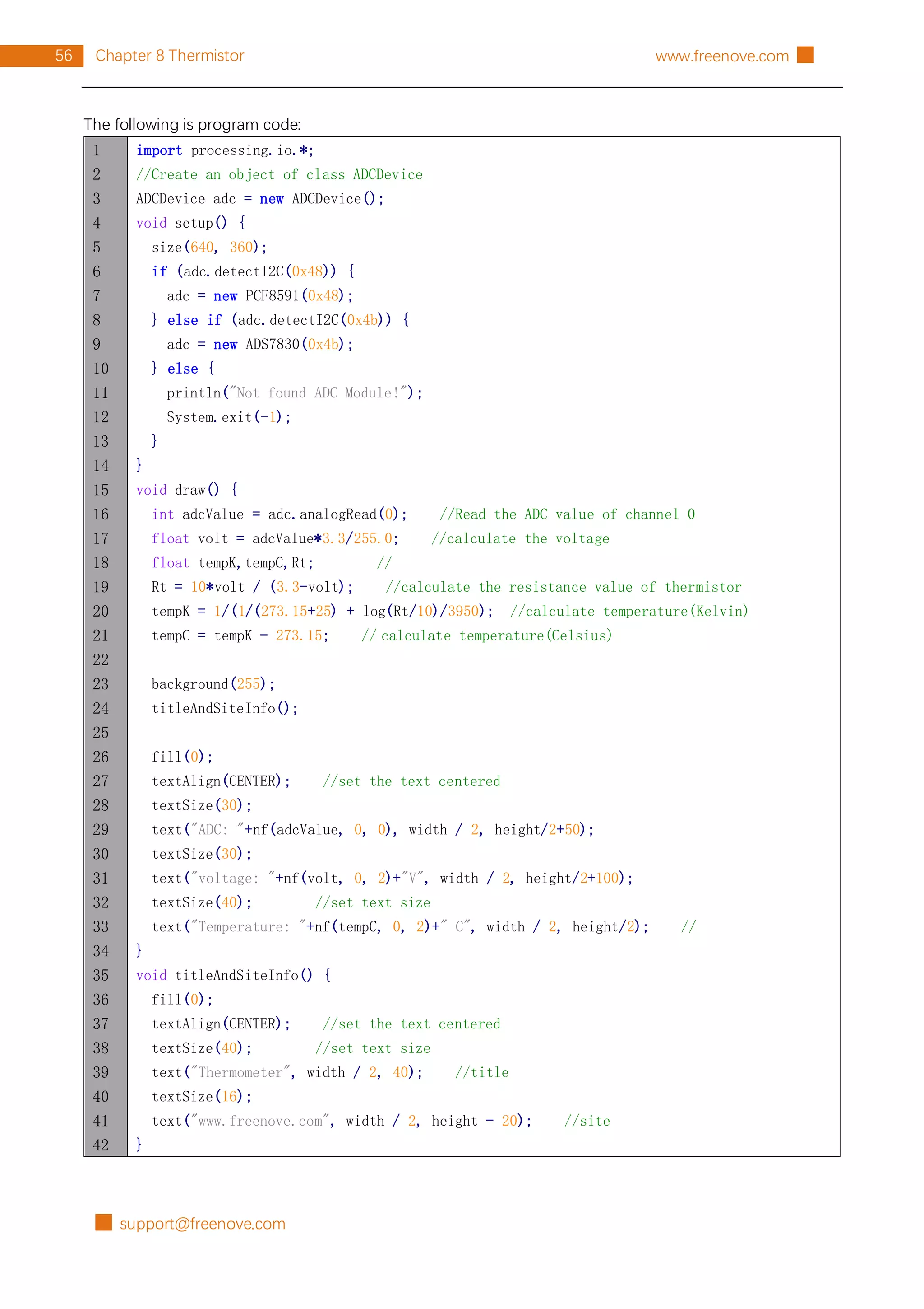
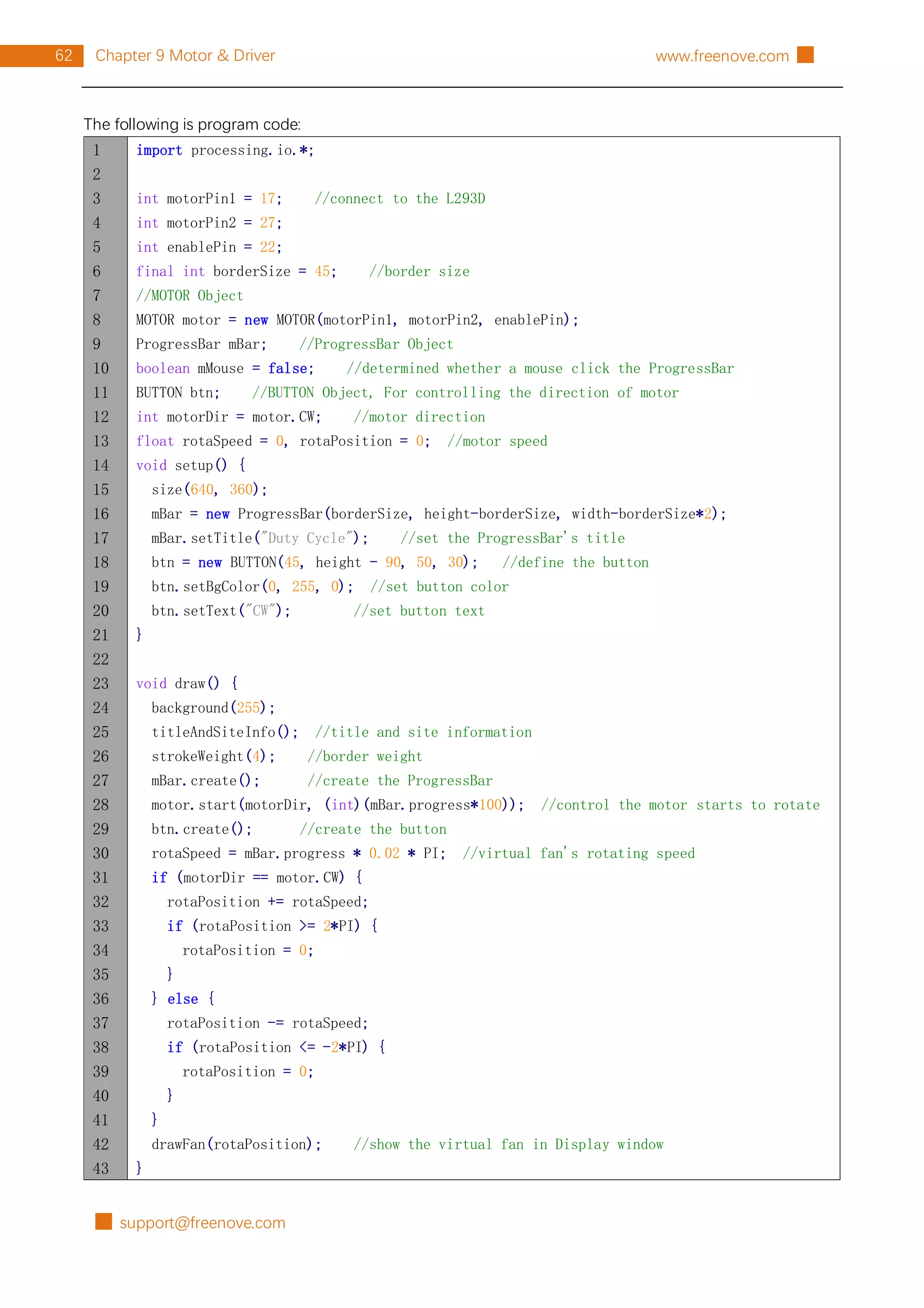
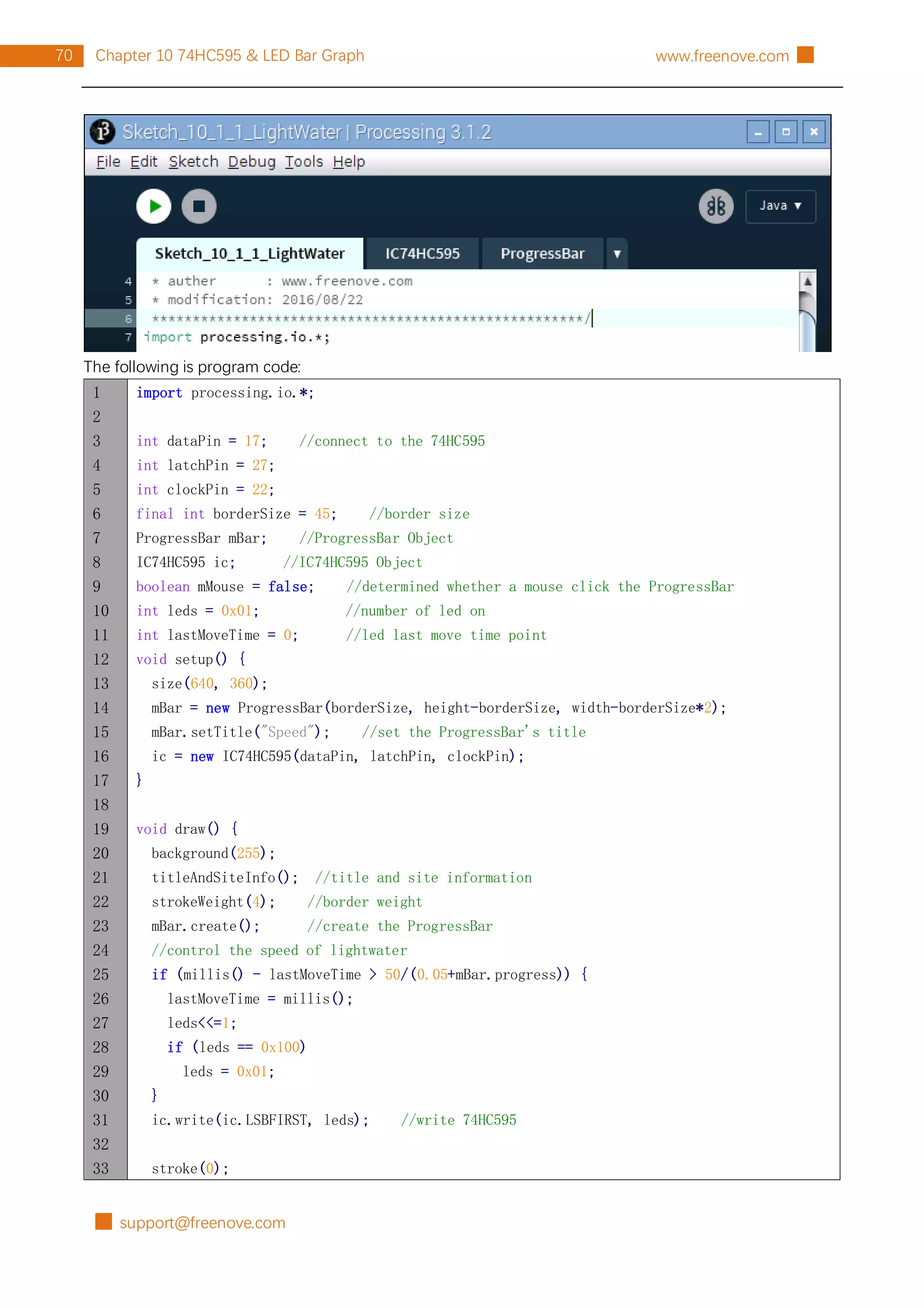
The following is program code:
1
2
3
4
5
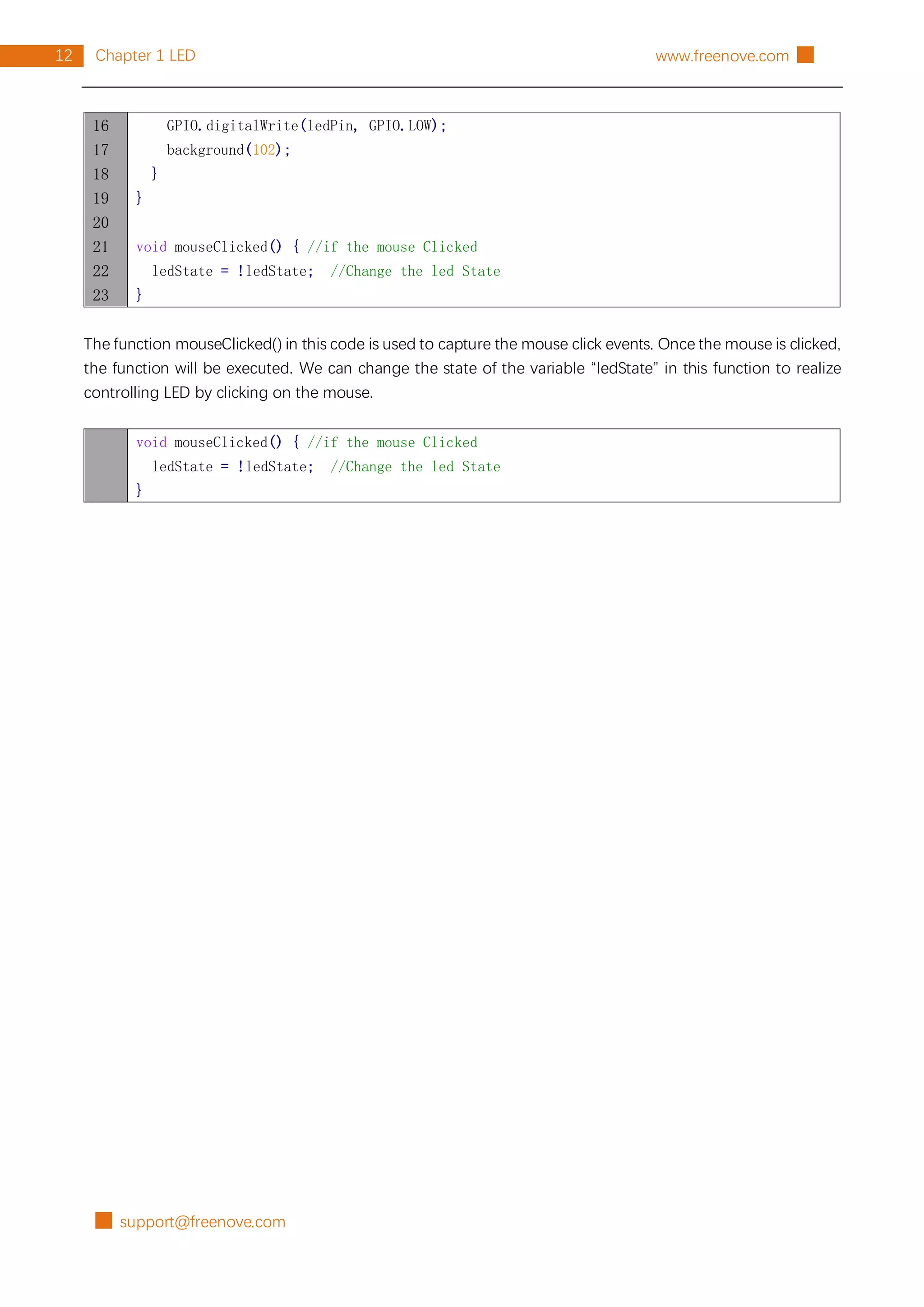
6
7
8
9
10
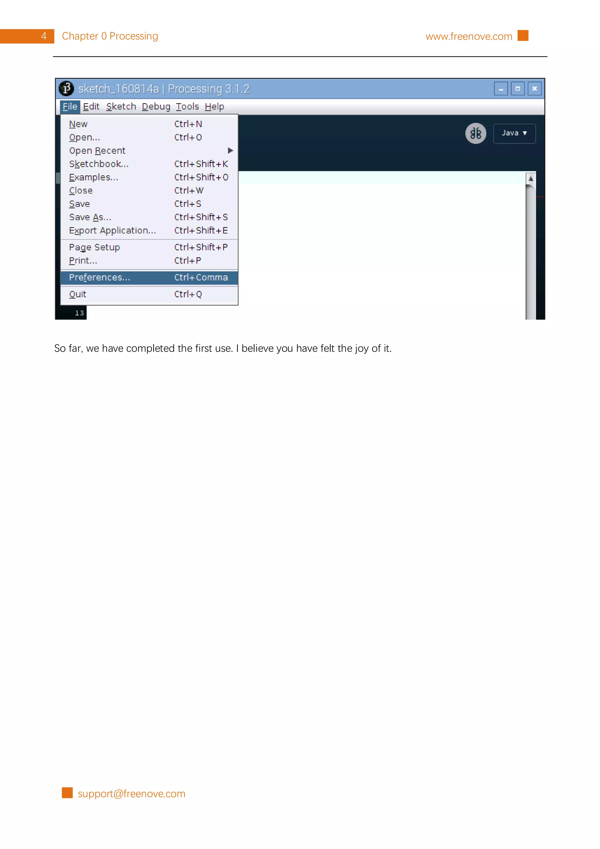
import processing.io.*;
int leds[]={17, 18, 27, 22, 23, 24, 25, 2, 3, 8}; //define ledPins
void setup() {
size(640, 360); //display window size
for (int i=0; i<10; i++) { //set led Pins to output mode
GPIO.pinMode(leds[i], GPIO.OUTPUT);
}
background(102);](https://image.slidesharecdn.com/processing-211120122651/75/Processing-language-19-2048.jpg)
![█ support@freenove.com
16 Chapter 2 LED Bar Graph www.freenove.com █
11
12
13
14
15
16
17
18
19
20
21
22
23
24
25
26
27
28
29
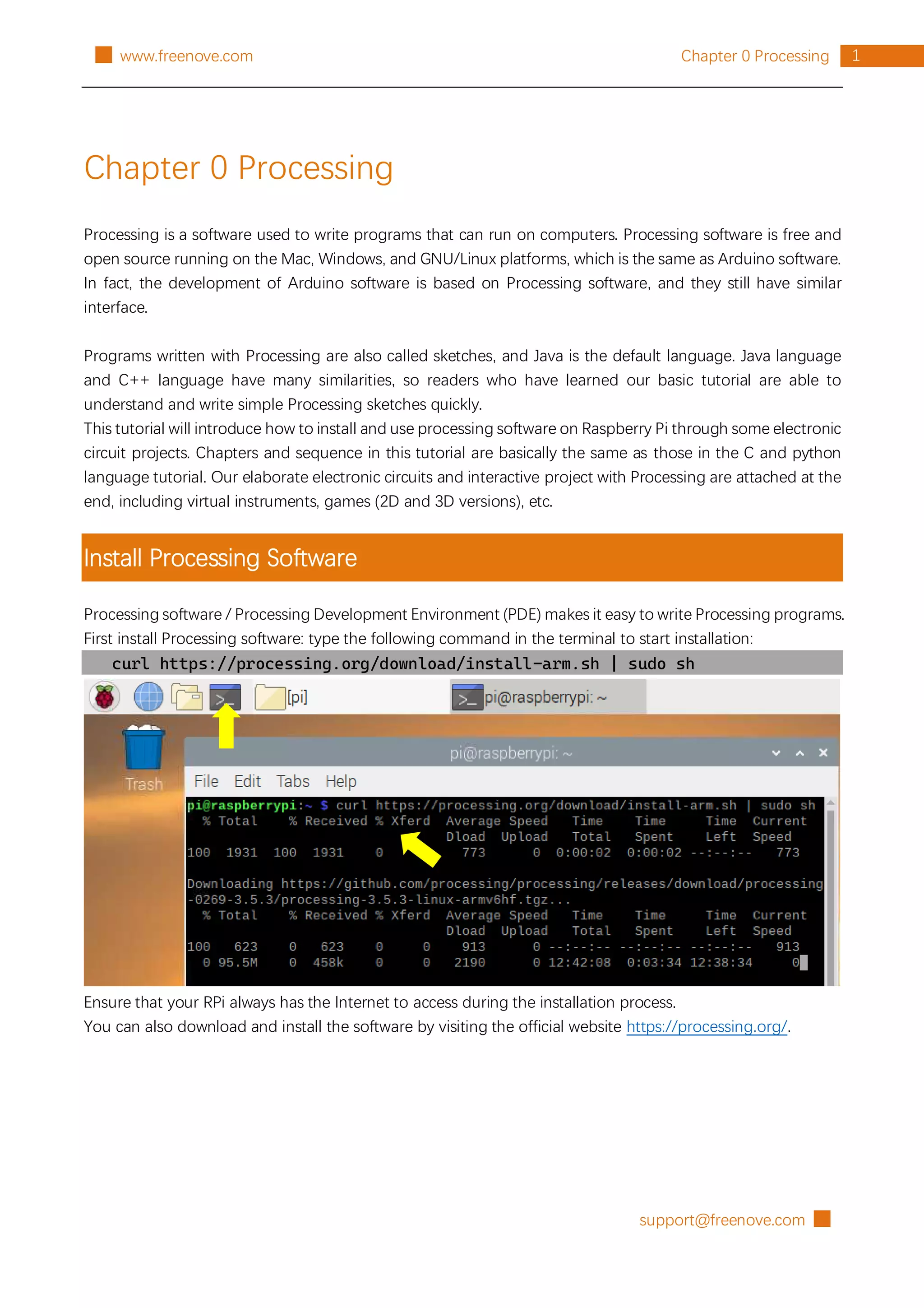
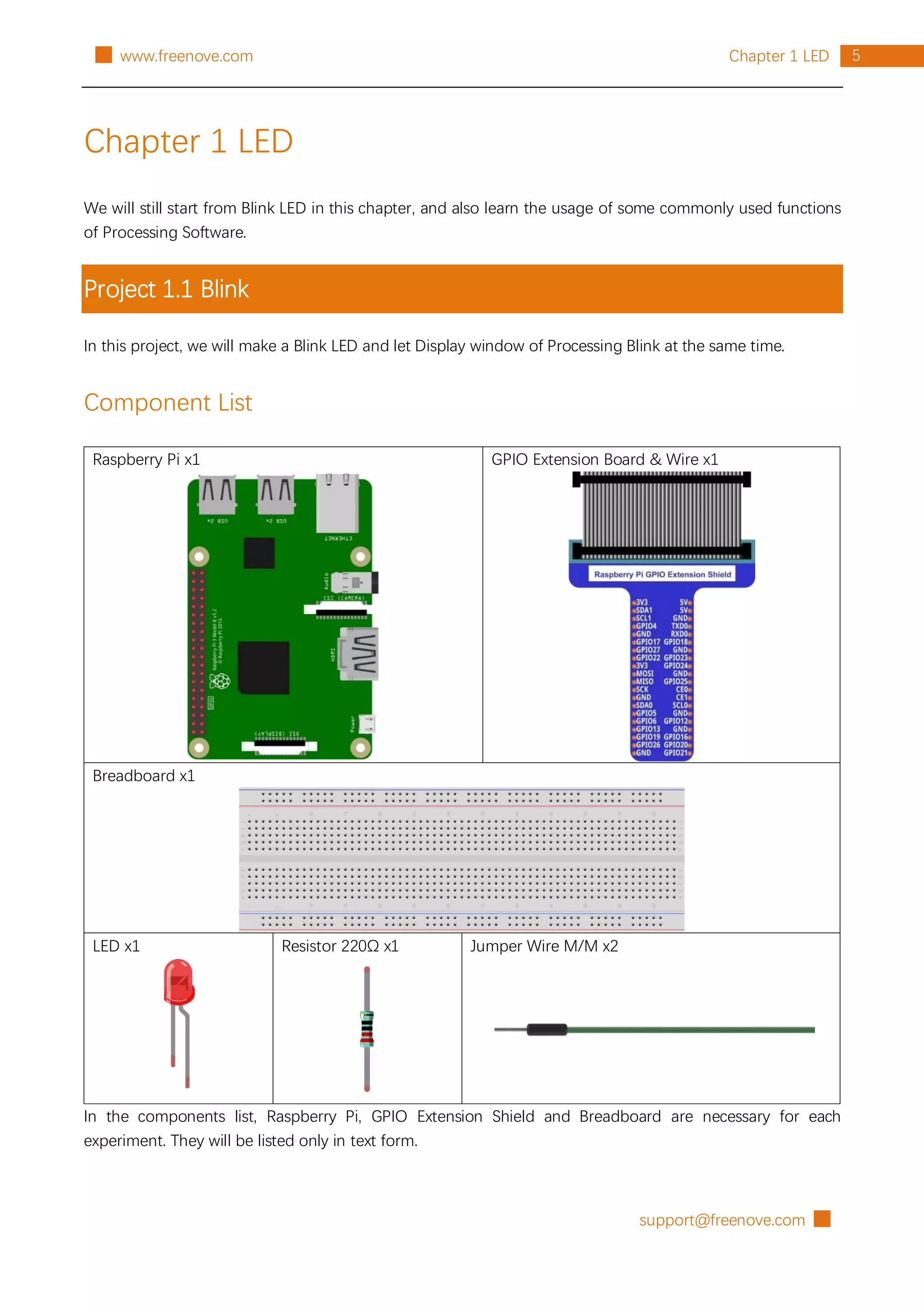
textAlign(CENTER); //set the text centered
textSize(40); //set text size
text("Follow Light", width / 2, 40); //title
textSize(16);
text("www.freenove.com", width / 2, height - 20); //site
}
void draw() {
for (int i=0; i<10; i++) { //draw 10 rectangular box
if (mouseX>(25+60*i)) { //if the mouse cursor on the right of rectangular box
fill(255, 0, 0); //fill the rectangular box in red color
GPIO.digitalWrite(leds[i], GPIO.LOW); //turn on the corresponding led
} else {
fill(255, 255, 255); //else fill the rectangular box in white color
GPIO.digitalWrite(leds[i], GPIO.HIGH); //and turn off the led
}
rect(25+60*i, 90, 50, 180); //draw a rectangular box
}
}
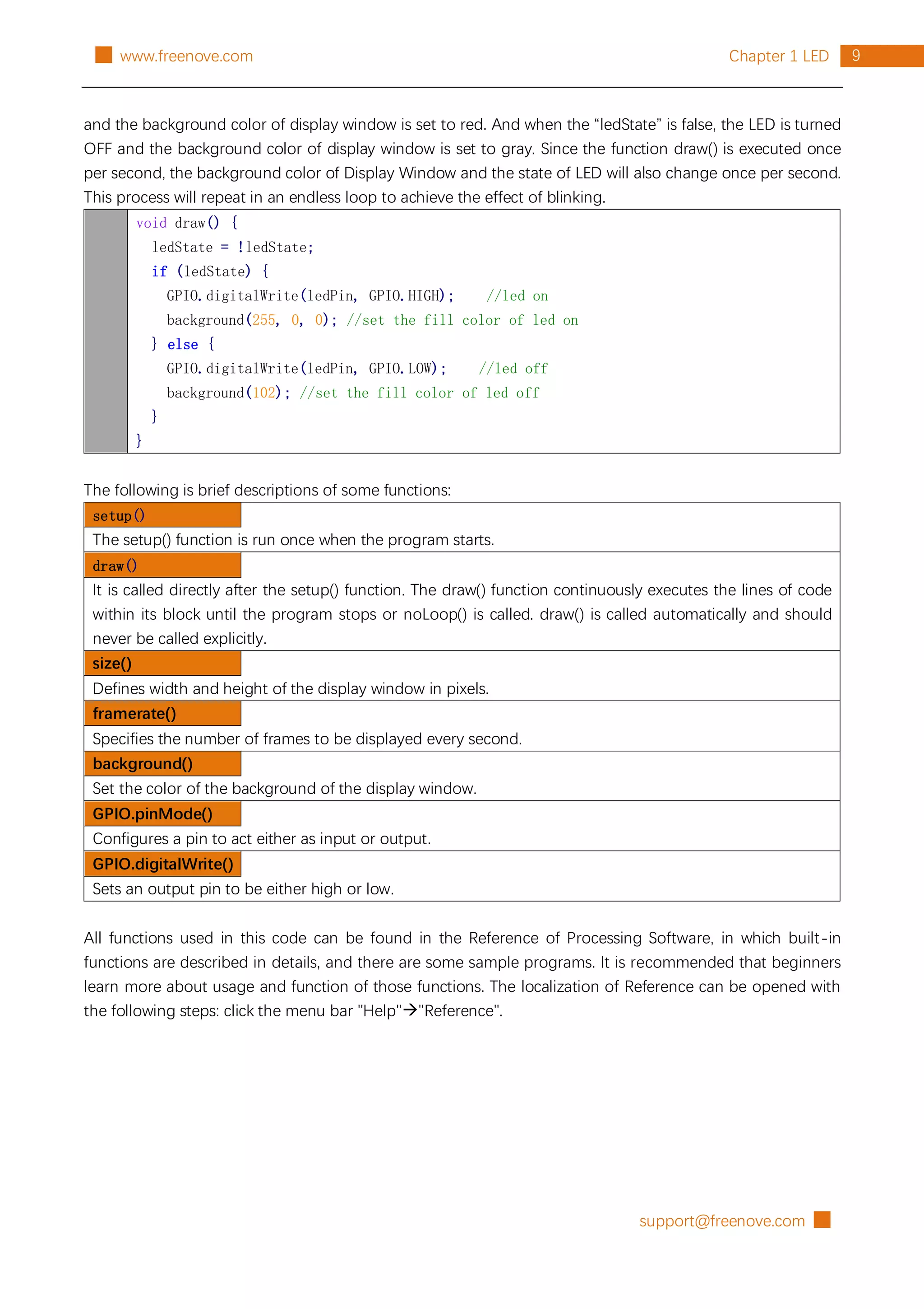
In the function draw(), we draw 10 rectangles to represent 10 LEDs of LED Bar Graph. We make rectangles on
the left of mouse filled with red, corresponding LEDs turned ON. And make We make rectangles on the right
of mouse filled with red, corresponding LEDs turned OFF. In this way, when slide the mouse to right, the more
LEDs on the left of mouse will be turned ON. When to the left, the reverse is the case.
void draw() {
for (int i=0; i<10; i++) { //draw 10 rectangular box
if (mouseX>(25+60*i)) { //if the mouse cursor on the right of rectangular box
fill (255, 0, 0); //fill the rectangular box in red color
GPIO.digitalWrite(leds[i], GPIO.LOW); //turn on the corresponding led
} else {
fill(255, 255, 255); //else fill the rectangular box in white color
GPIO.digitalWrite(leds[i], GPIO.HIGH); //and turn off the led
}
rect(25+60*i, 90, 50, 180); //draw a rectangular box
}
}](https://image.slidesharecdn.com/processing-211120122651/75/Processing-language-20-2048.jpg)

![█ support@freenove.com
42 Chapter 6 ADC Module www.freenove.com █
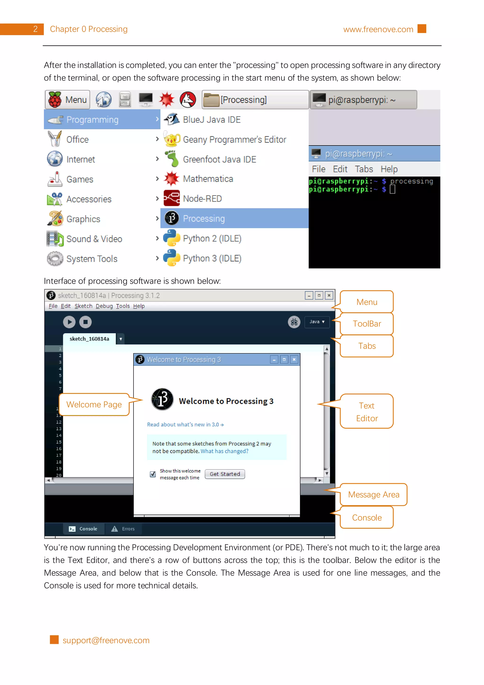
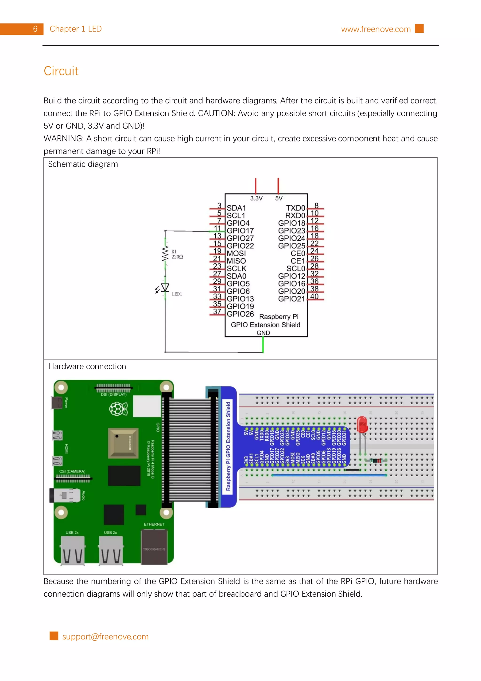
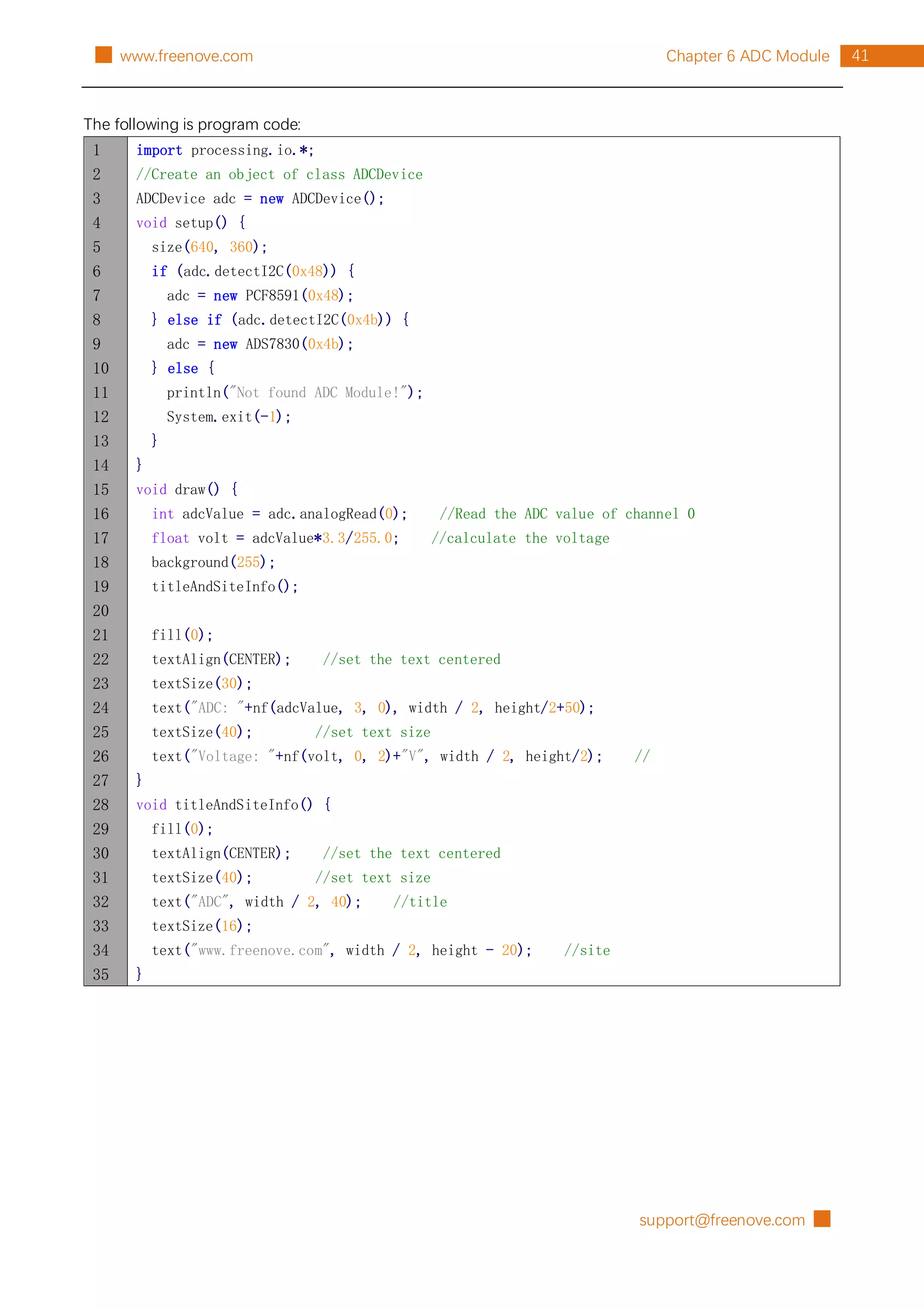
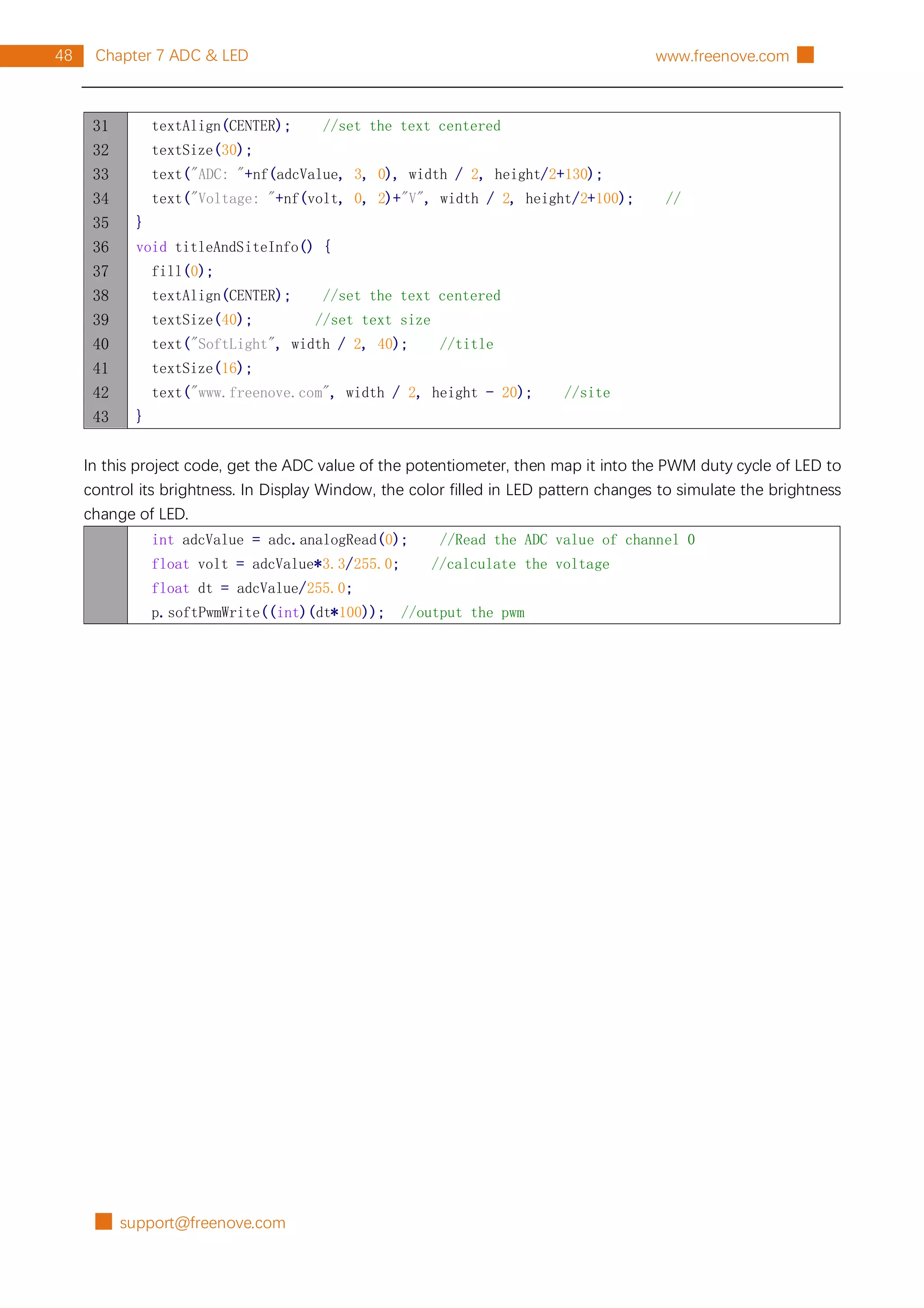
The code of this project mainly uses PCF8591 class member function analogRead() to read ADC.
int adcValue = adc.analogRead(0); //Read the ADC value of channel 0
float volt = adcValue*3.3/255.0; //calculate the voltage
About class ADCDevice, PCF8591, ADS7830:
class ADCDevice
This is a base class, and all ADC module classes are subclasses of it. It provides two basic member functions.
public int analogRead(int chn)
This is a unified function name. Different chips have different implement methods. Therefore, specific
method is implemented in subclasses.
public boolean detectI2C(int addr)
Used to detect I2C device with a given address. If it exists, it returns true, otherwise it returns false.
class PCF8591 extends ADCDevice
This is a custom class that is used to operate the ADC and DAC of PCF8591.
public PCF8591(int addr)
Constructor, used to create a PCF8591 class object, parameters for the I2C PCF8591 device address.
public int analogRead(int chn)
Used to read ADC value of one channel of PCF8591, the parameter CHN indicates the channel number:
0,1,2,3.
public byte[] analogRead()
To read ADC values of all channels of PCF8591.
public void analogWrite(int data)
Write a DAC value to PCF8591.
class ADS7830 extends ADCDevice
This is a custom class that is used to operate the ADC of ADS7830.
public ADS7830(int addr)
Constructor, used to create a ADS7830 class object, parameters for the I2C ADS7830 device address.
public int analogRead(int chn)
Used to read ADC value of one channel of ADS7830, the parameter CHN indicates the channel number:
0,1,2,3,4,5,6,7.](https://image.slidesharecdn.com/processing-211120122651/75/Processing-language-46-2048.jpg)
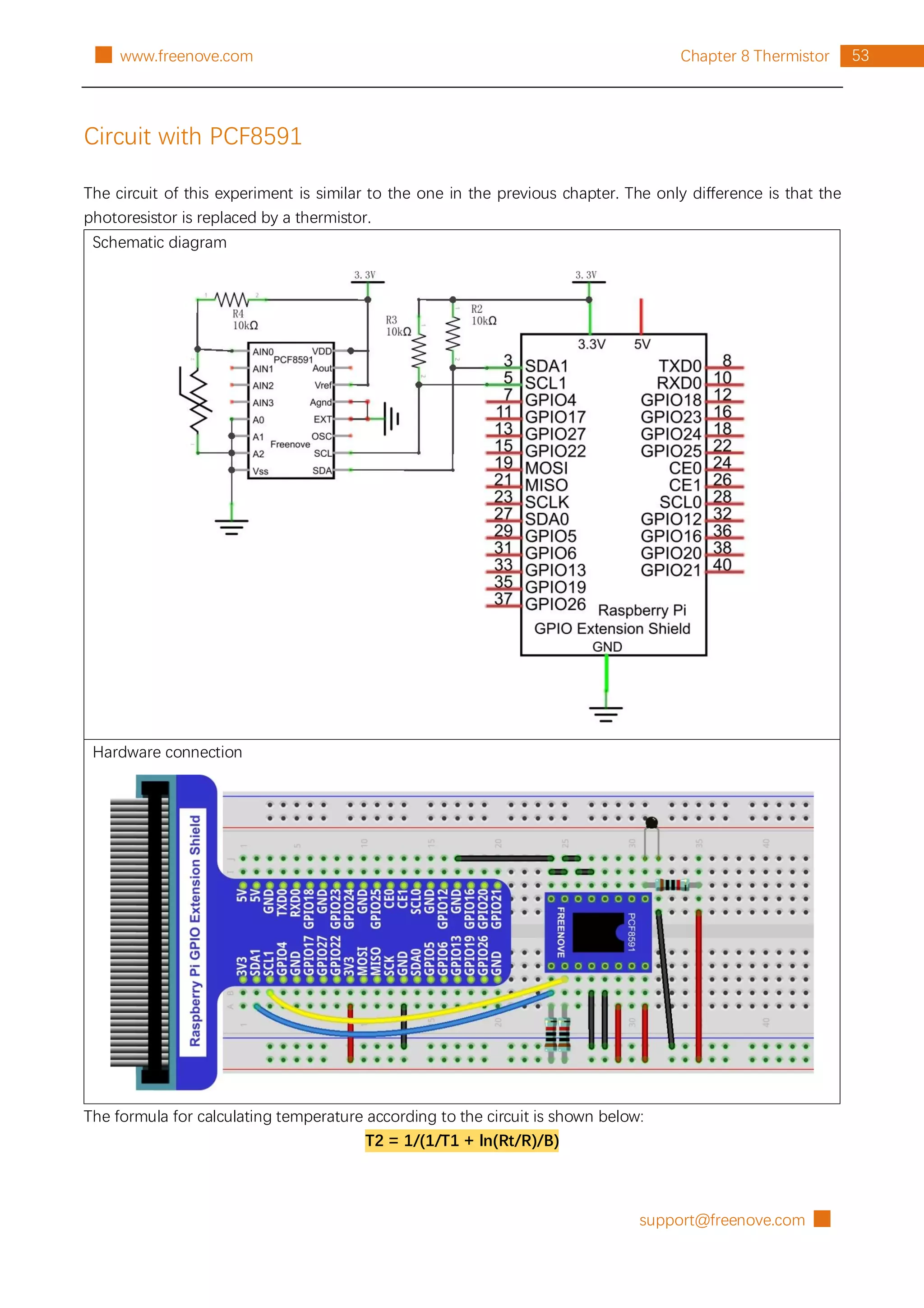
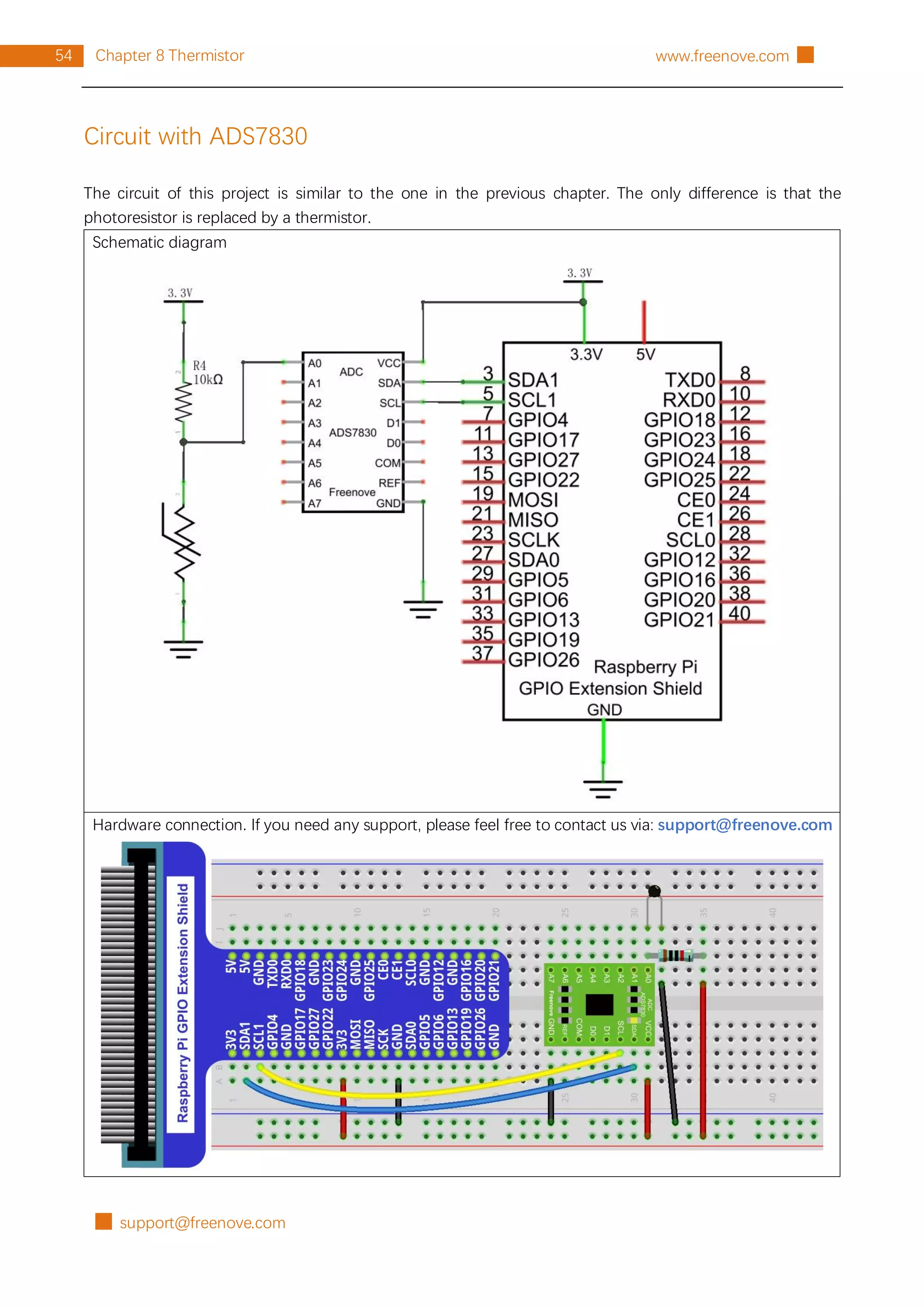
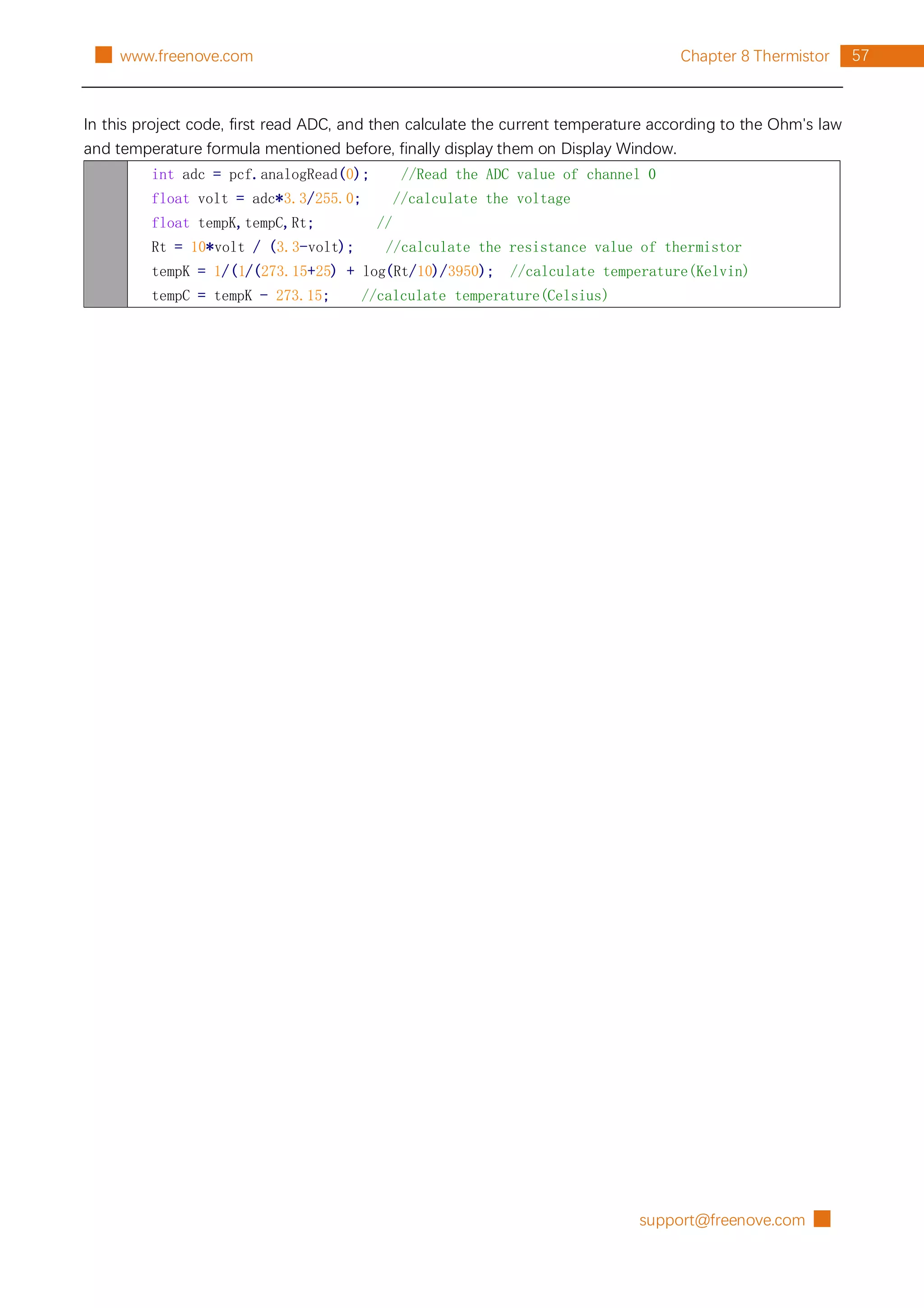
![█ support@freenove.com
52 Chapter 8 Thermistor www.freenove.com █
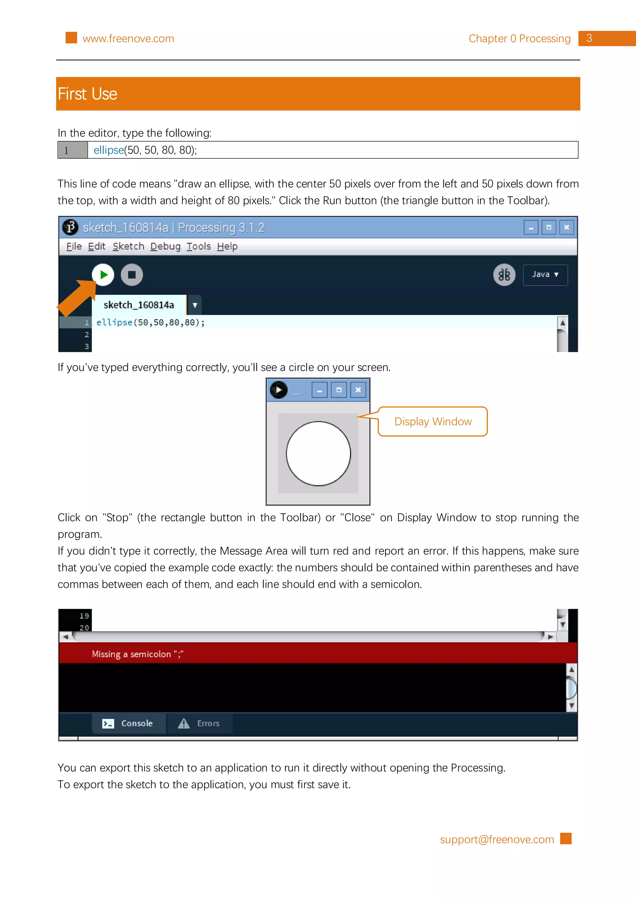
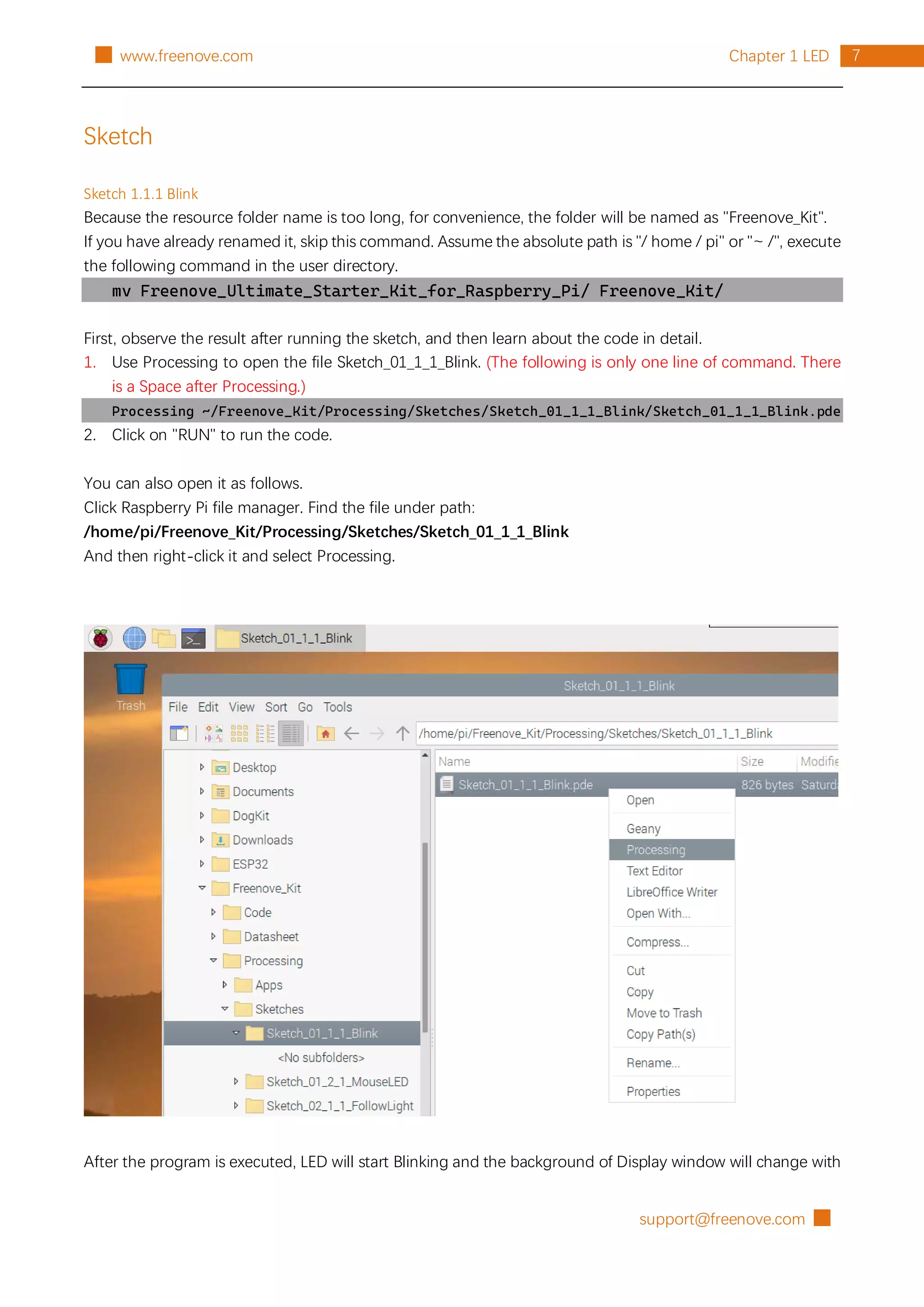
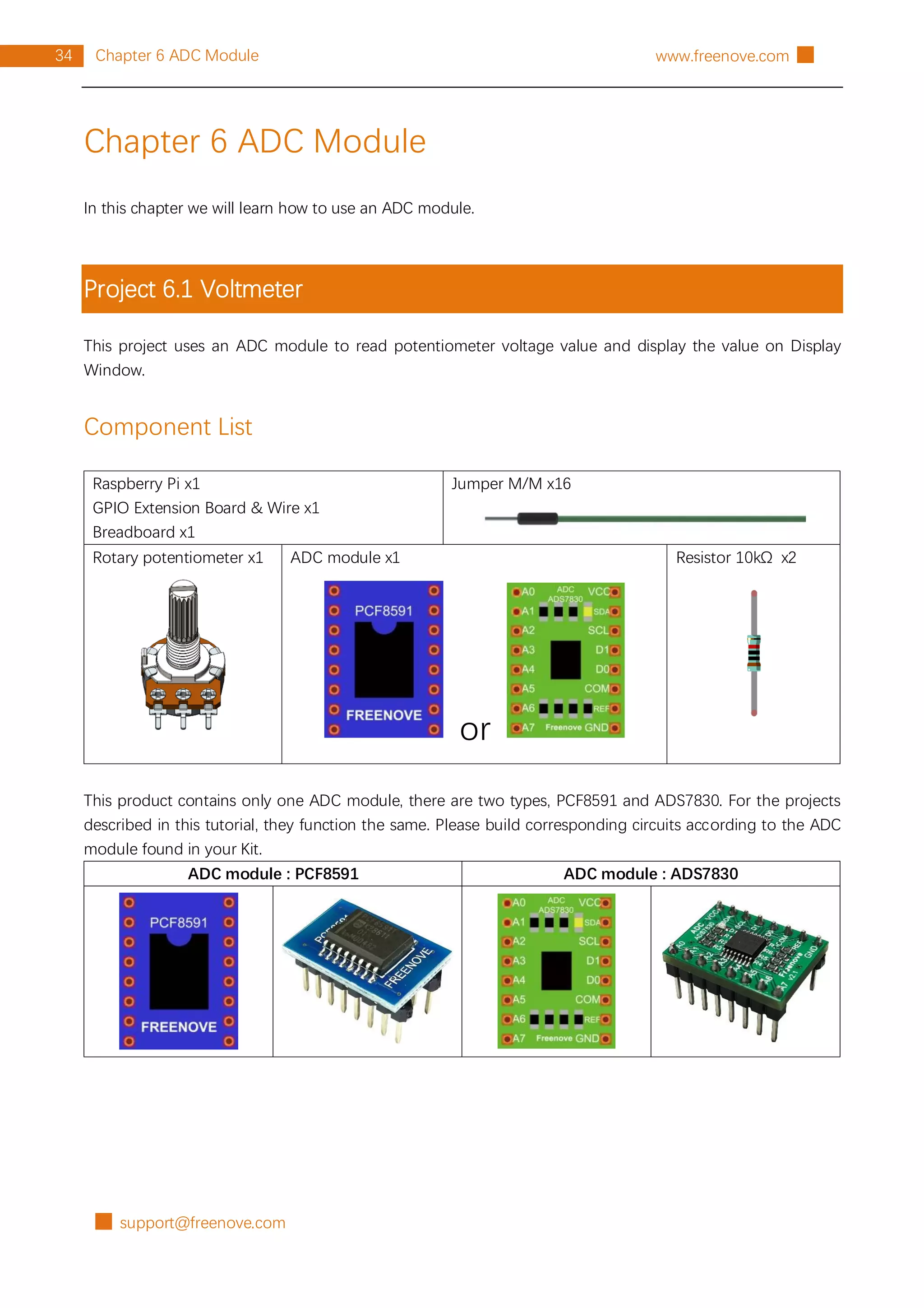
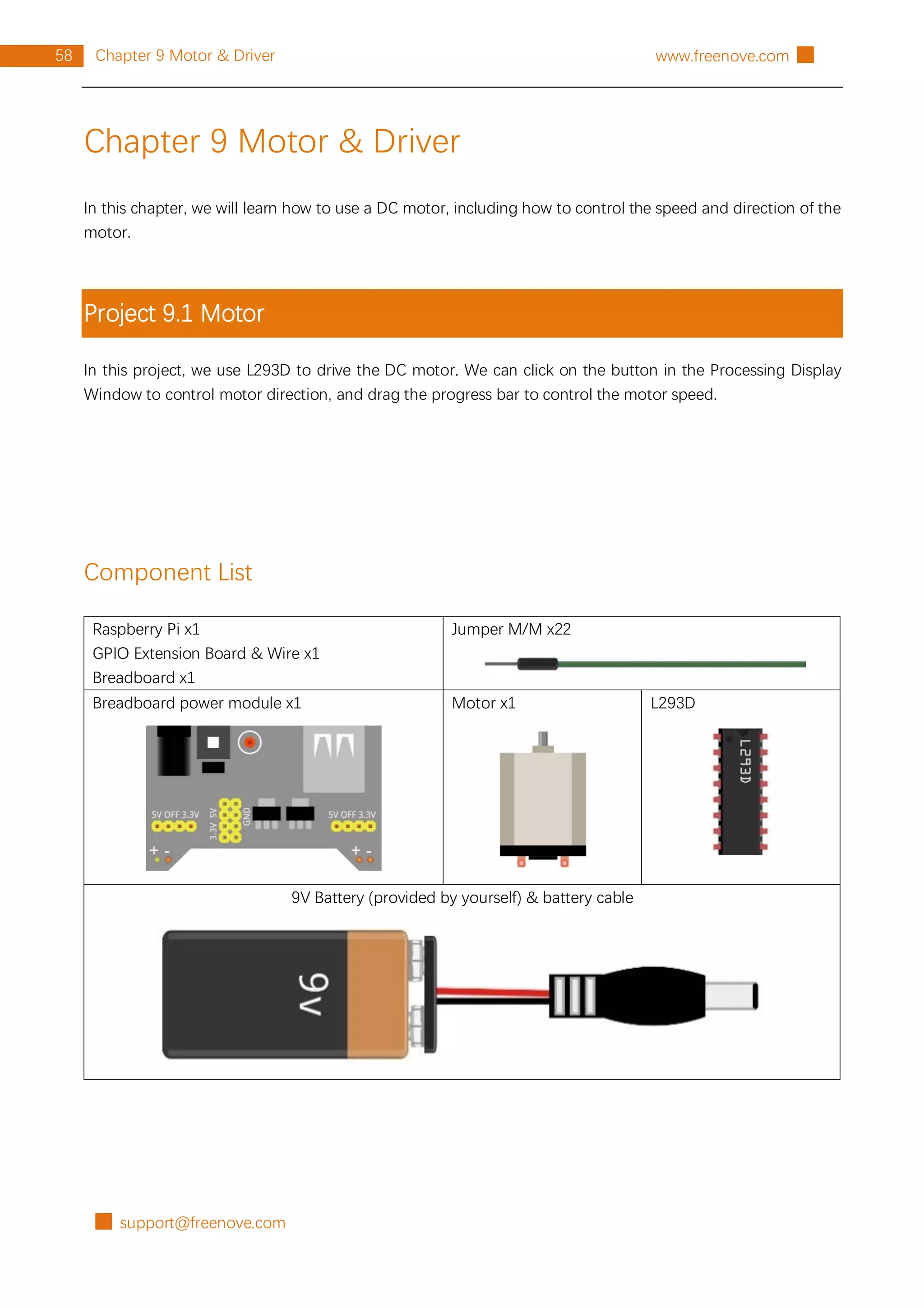
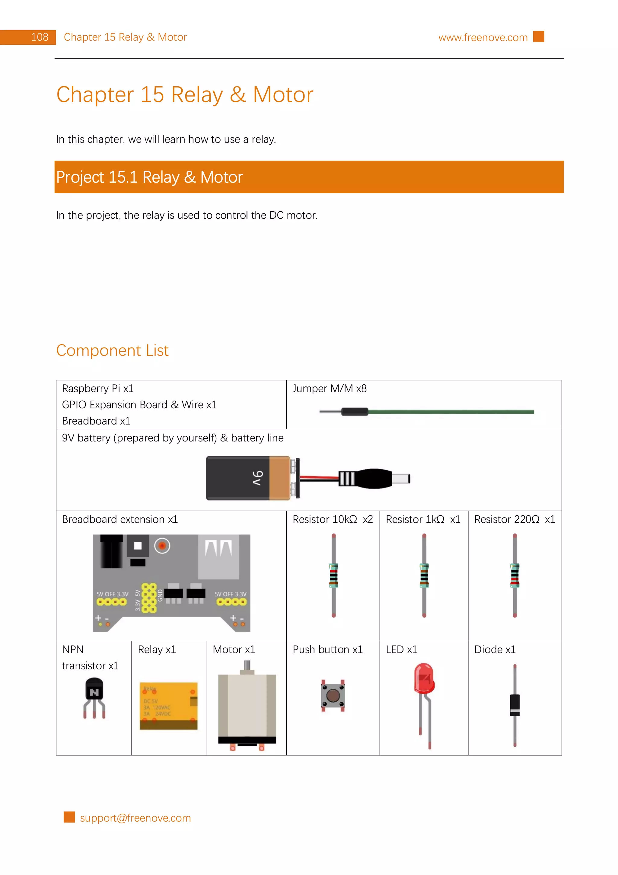
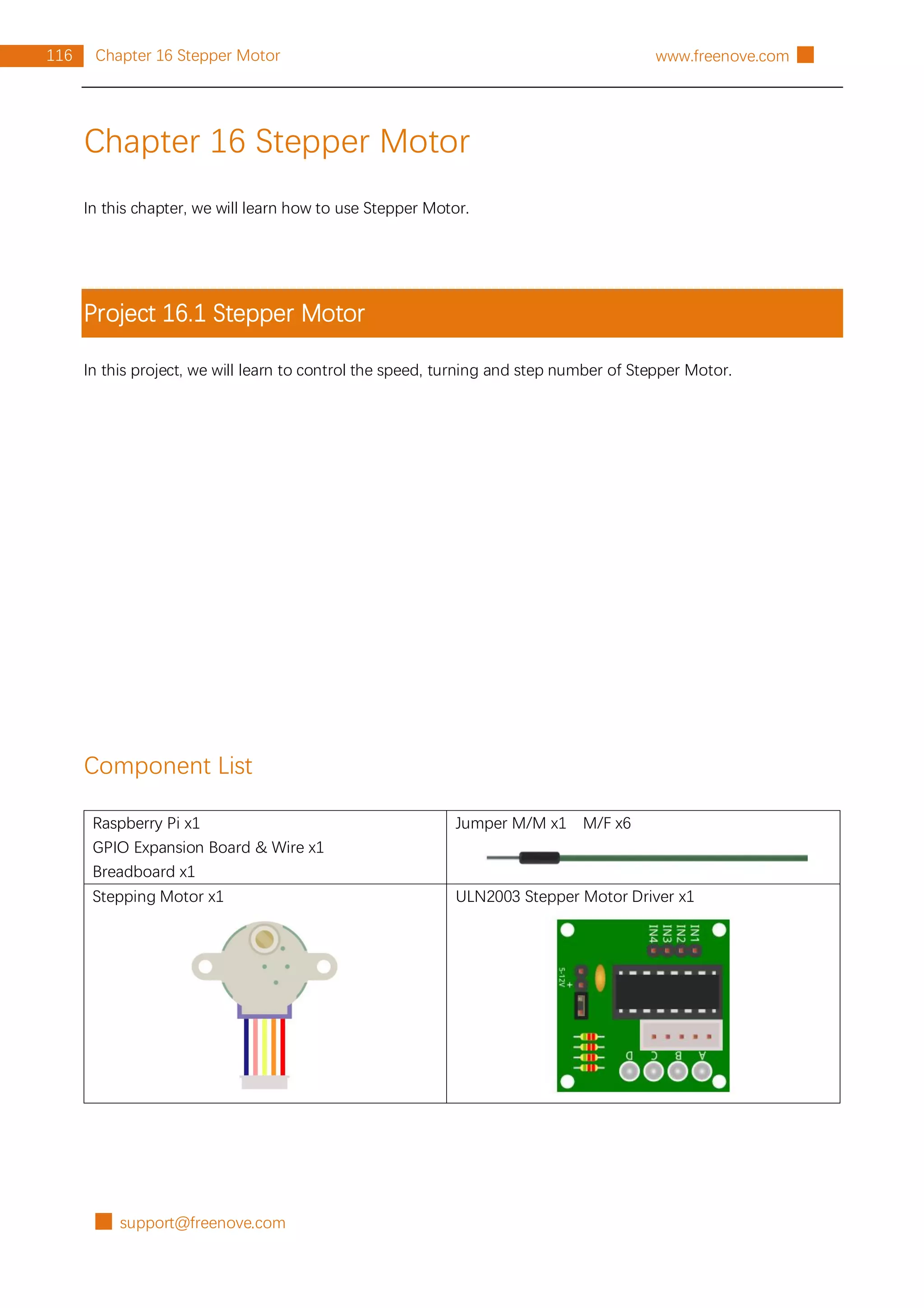
Chapter 8 Thermistor
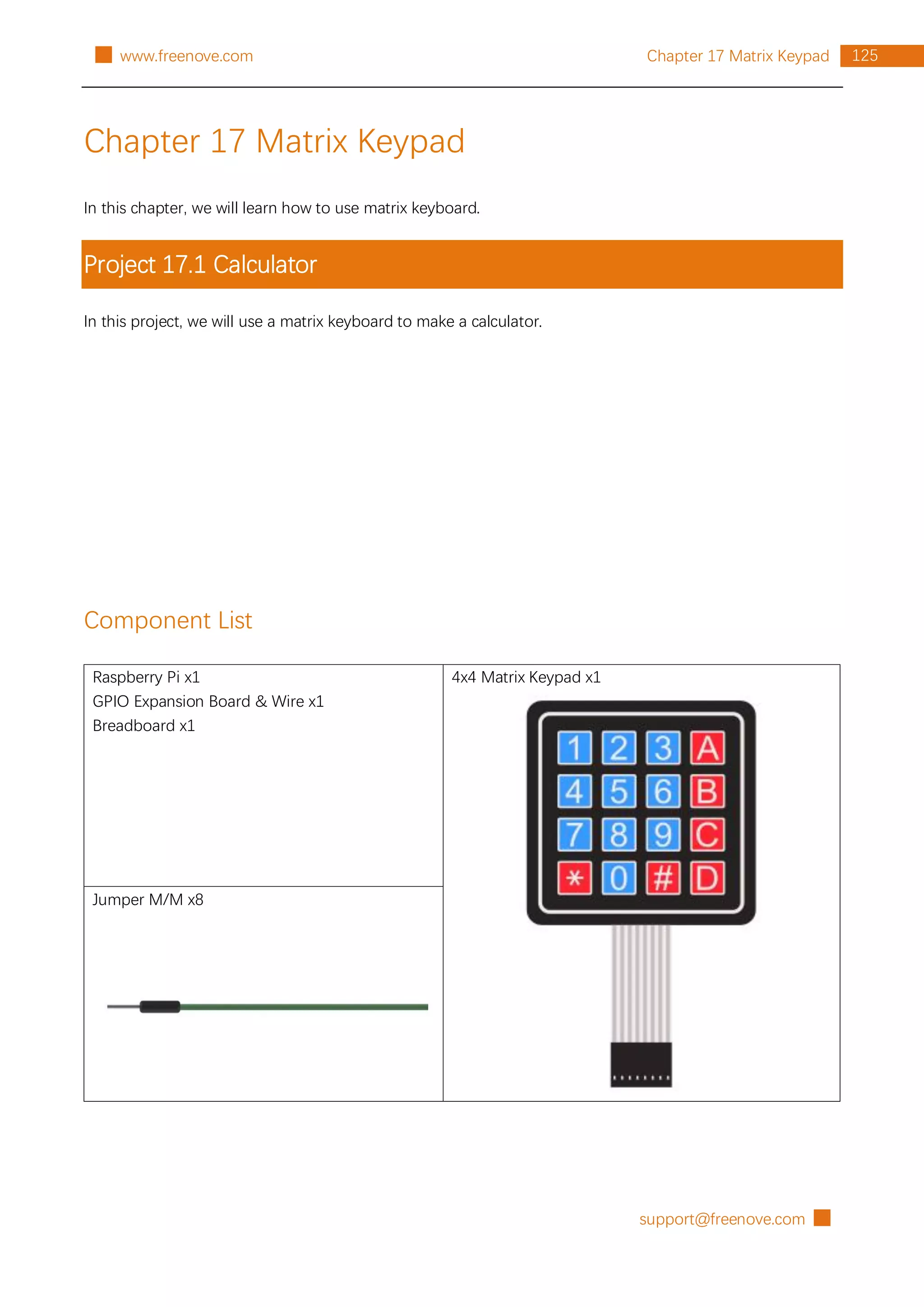
In this chapter, we will learn how to use a thermistor.
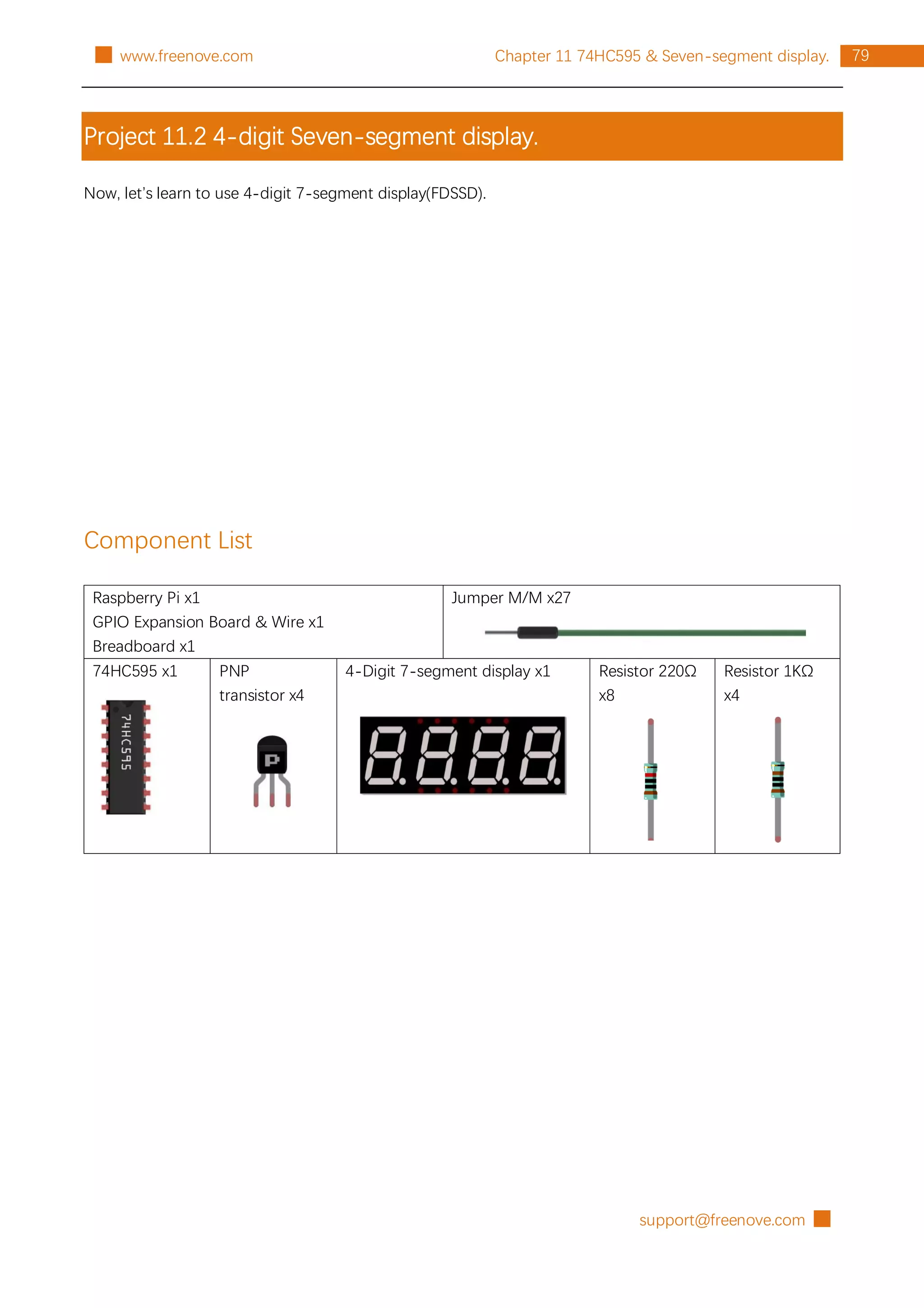
Project 8.1 Thermometer
In this project, we will use a thermistor to make a thermometer.
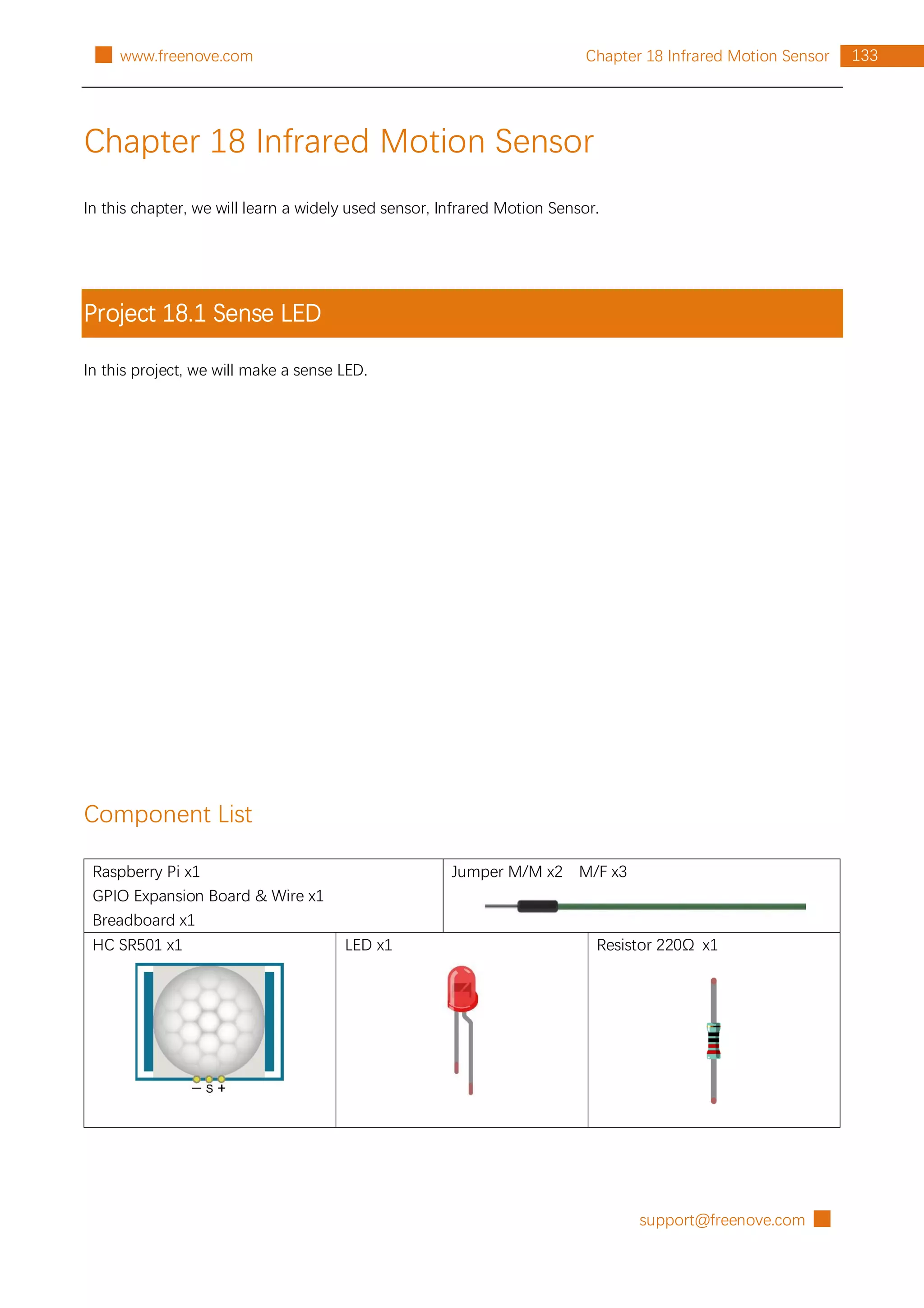
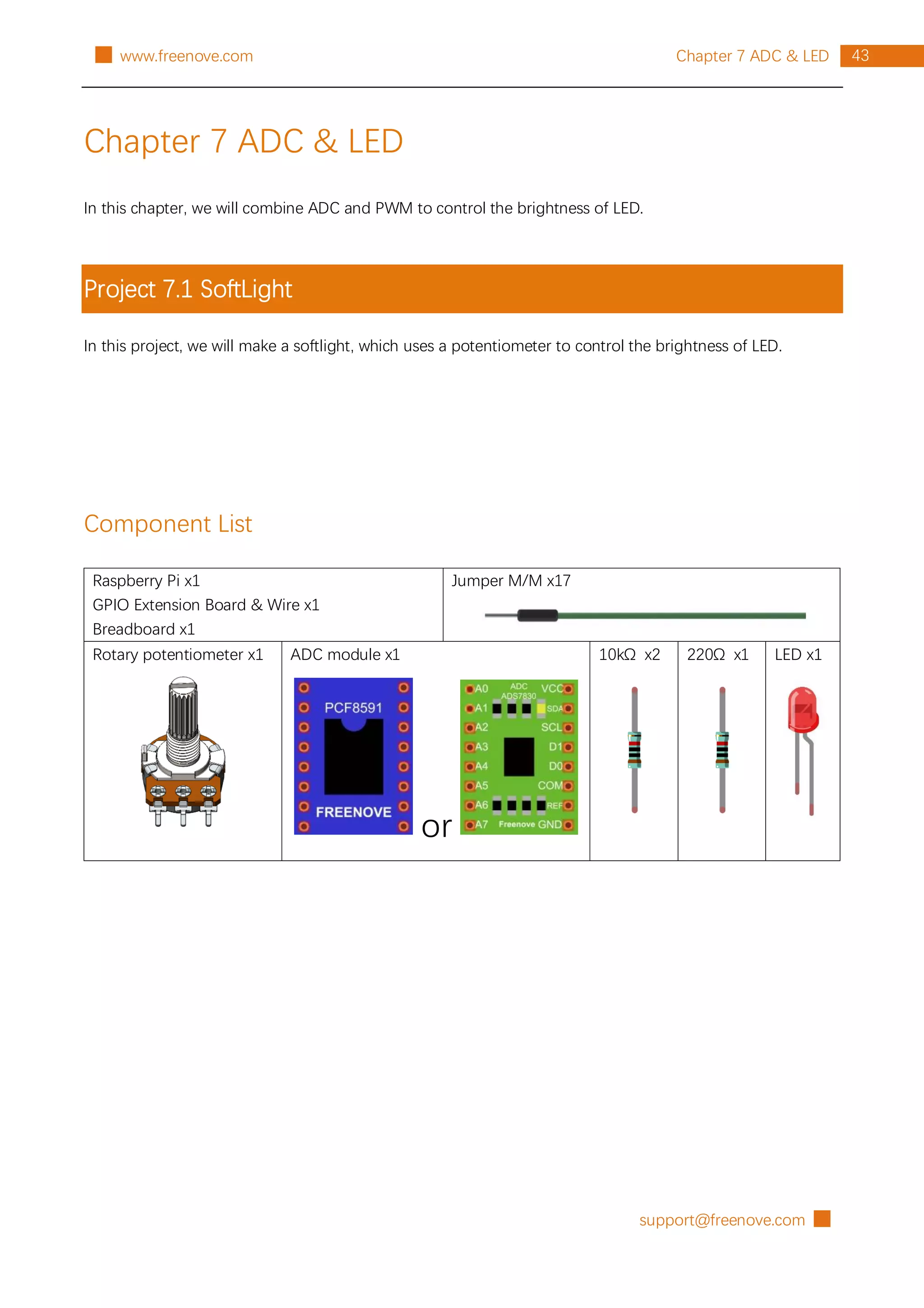
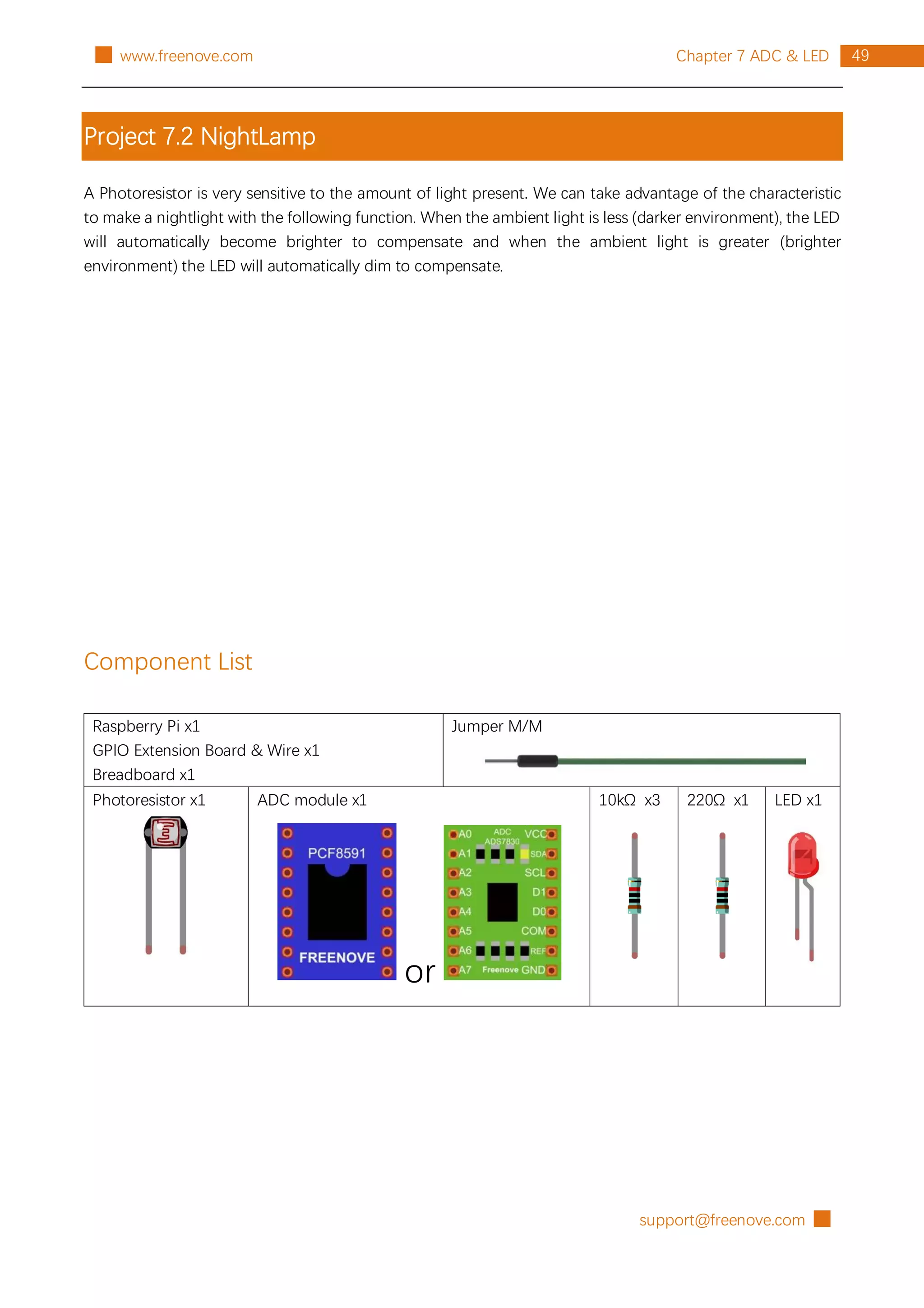
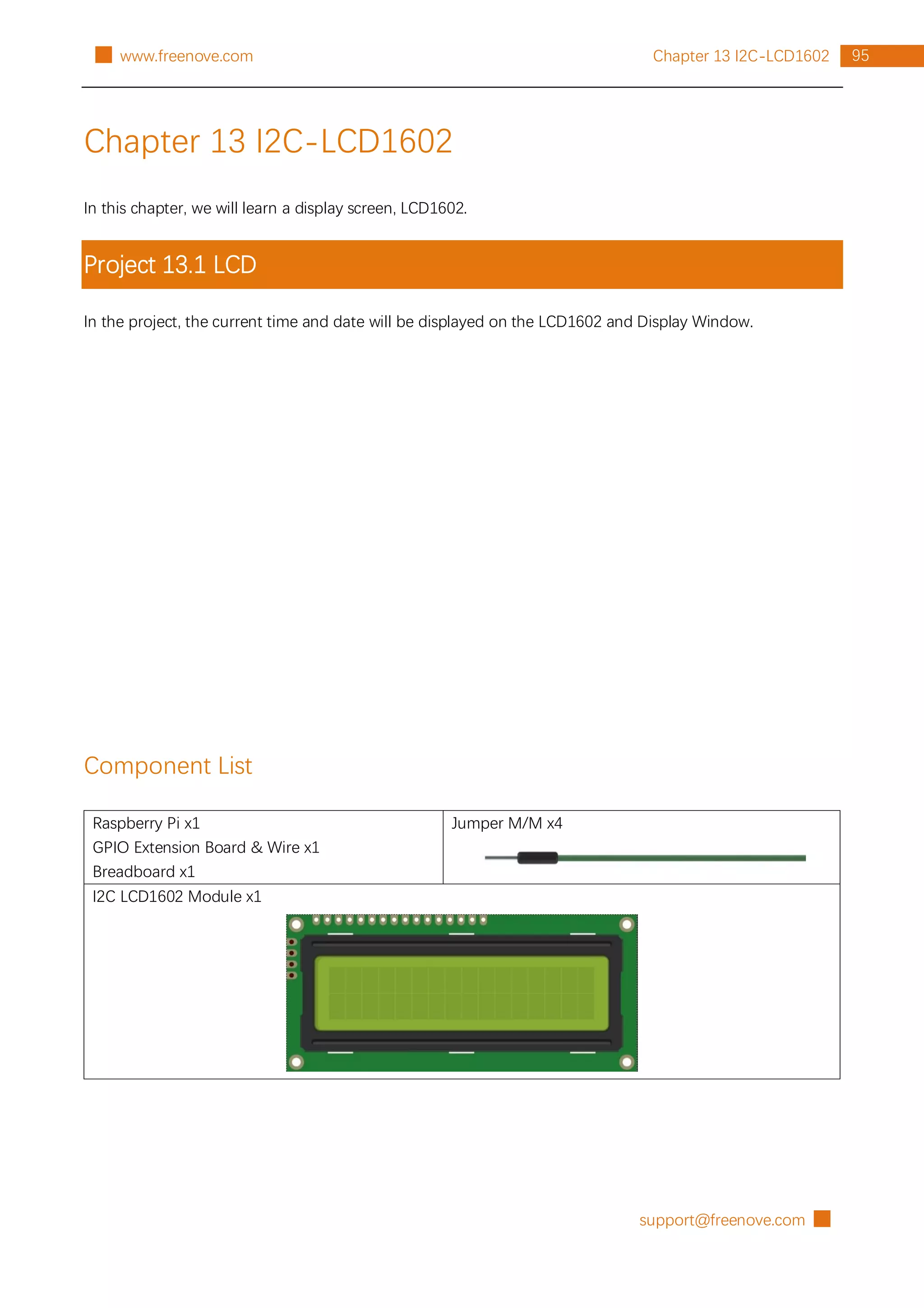
Component List
Raspberry Pi x1
GPIO Extension Board & Wire x1
Breadboard x1
Jumper M/M
Thermistor x1 ADC module x1
or
Resistor 10kΩ x3
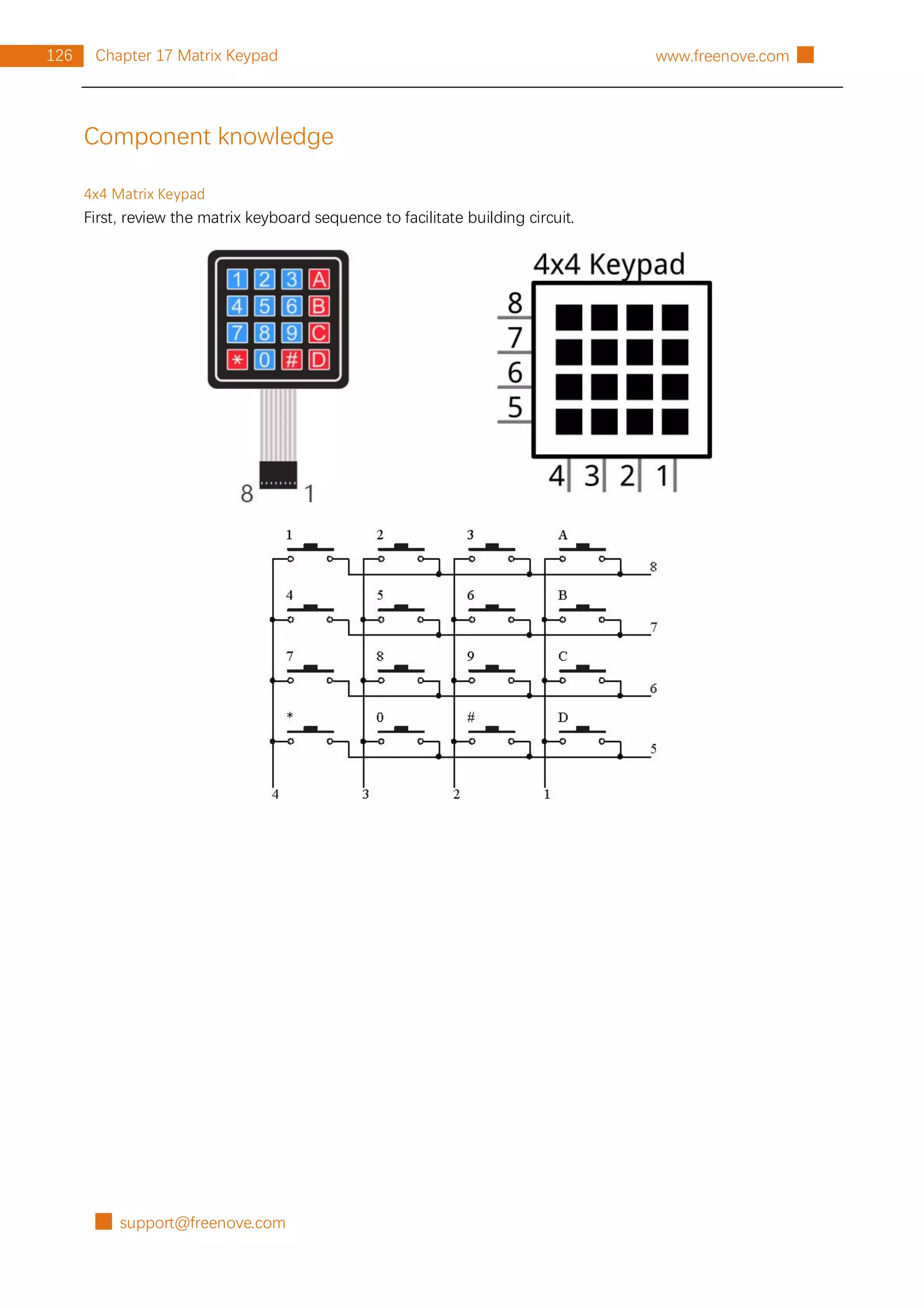
Component knowledge
First Review the knowledge of thermistor. The relationship between resistance value and temperature of
thermistor is:
Rt=R*EXP [B*(1/T2-1/T1)]
Where:
Rt is the thermistor resistance under T2 temperature;
R is in the nominal resistance of thermistor under T1 temperature;
EXP[n] is nth power of e;
B is for thermal index;
T1, T2 is Kelvin temperature (absolute temperature). Kelvin temperature=273.15+celsius temperature.
Parameters of the thermistor we use is: B=3950, R=10k, T1=25.](https://image.slidesharecdn.com/processing-211120122651/75/Processing-language-56-2048.jpg)
![█ support@freenove.com
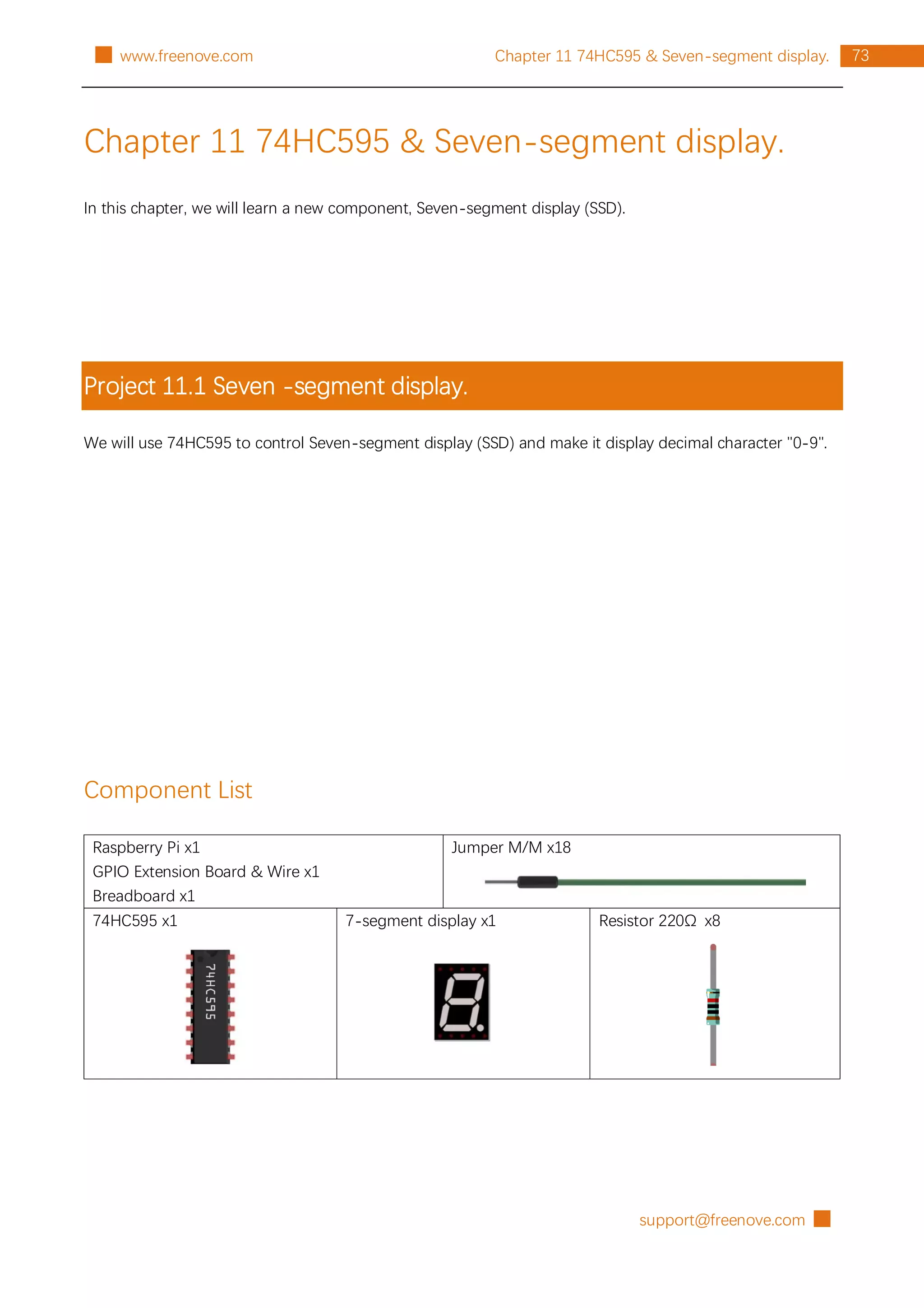
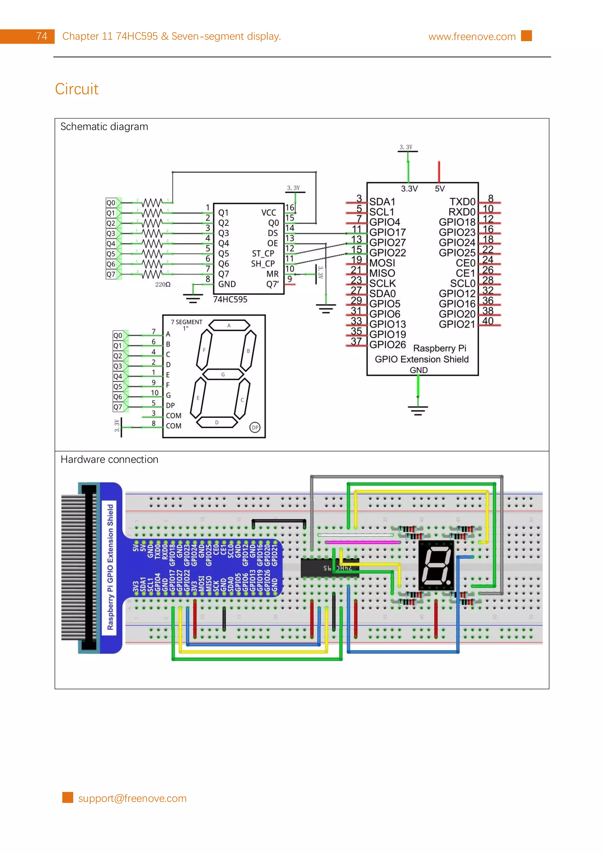
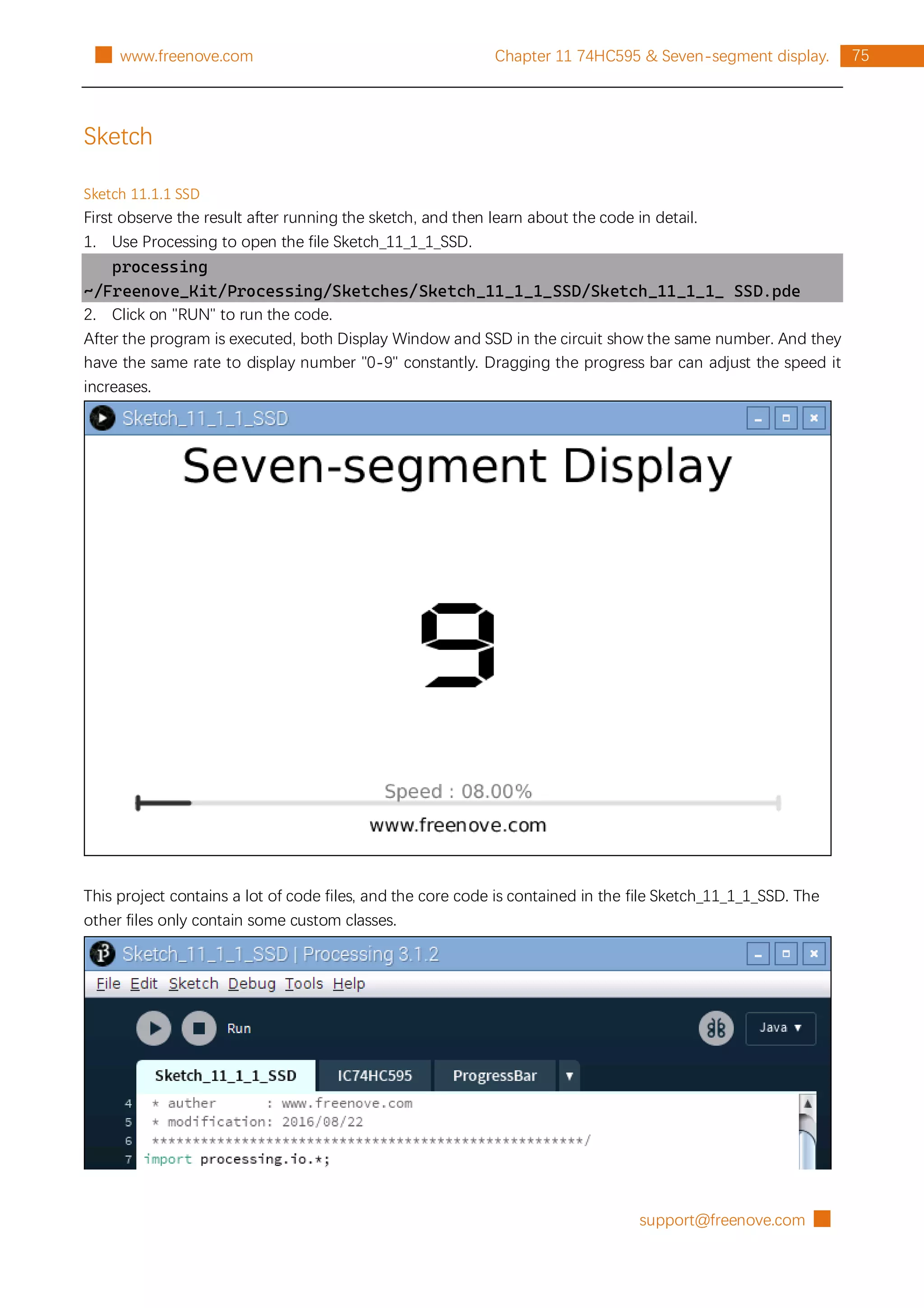
76 Chapter 11 74HC595 & Seven-segment display. www.freenove.com █
The following is program code:
1
2
3
4
5
6
7
8
9
10
11
12
13
14
15
16
17
18
19
20
21
22
23
24
25
26
27
28
29
30
31
32
33
34
35
36
37
38
39
40
41
42
43
import processing.io.*;
int dataPin = 17; //connect to the 74HC595
int latchPin = 27;
int clockPin = 22;
final int borderSize = 45; //border size
ProgressBar mBar; //ProgressBar Object
IC74HC595 ic; //IC74HC595 Object
boolean mMouse = false; //determined whether a mouse click the ProgressBar
int index = 0; // index of number
int lastMoveTime = 0; //led last move time point
//encoding for character 0-9 of common anode SevenSegmentDisplay
final int[] numCode = {0xc0, 0xf9, 0xa4, 0xb0, 0x99, 0x92, 0x82, 0xf8, 0x80, 0x90};
PFont mFont;
void setup() {
size(640, 360);
mBar = new ProgressBar(borderSize, height-borderSize, width-borderSize*2);
mBar.setTitle("Speed"); //set the ProgressBar's title
ic = new IC74HC595(dataPin, latchPin, clockPin);
mFont = loadFont("DigifaceWide-100.vlw"); //create DigifaceWide font
}
void draw() {
background(255);
titleAndSiteInfo(); //title and site information
strokeWeight(4); //border weight
mBar.create(); //create the ProgressBar
//control the speed of number change
if (millis() - lastMoveTime > 50/(0.05+mBar.progress)) {
lastMoveTime = millis();
index++;
if (index > 9) {
index = 0;
}
}
ic.write(ic.MSBFIRST, numCode[index]); //write 74HC595
showNum(index); //show the number in display window
}
void showNum(int num) {
fill(0);
textSize(100);
textFont(mFont); //digiface font](https://image.slidesharecdn.com/processing-211120122651/75/Processing-language-80-2048.jpg)
![support@freenove.com █
77
Chapter 11 74HC595 & Seven-segment display.
█ www.freenove.com
44
45
46
47
48
49
50
51
52
53
54
55
56
57
58
59
60
61
62
63
64
65
66
67
68
69
textAlign(CENTER, CENTER);
text(num, width/2, height/2);
}
void mousePressed() {
if ( (mouseY< mBar.y+5) && (mouseY>mBar.y-5) ) {
mMouse = true; //the mouse clicks the progressBar
}
}
void mouseReleased() {
mMouse = false;
}
void mouseDragged() {
int a = constrain(mouseX, borderSize, width - borderSize);
float t = map(a, borderSize, width - borderSize, 0.0, 1.0);
if (mMouse) {
mBar.setProgress(t);
}
}
void titleAndSiteInfo() {
fill(0);
textAlign(CENTER); //set the text centered
textFont(createFont("", 100)); //default font
textSize(40); //set text size
text("Seven-segment Display", width / 2, 40); //title
textSize(16);
text("www.freenove.com", width / 2, height - 20); //site
}
The project code is similar to the previous chapter. The difference is that in this project the data output by
74HC595 is the fixed coding information of SSD. First, the character "0-9" is defined as code of common
anode SSD.
final int[] numCode = {0xc0, 0xf9, 0xa4, 0xb0, 0x99, 0x92, 0x82, 0xf8, 0x80, 0x90};
In the function draw(), the data is output at a certain speed. At the same time the Display Window outputs
the same character.
if (millis() - lastMoveTime > 50/(0.05+mBar.progress)) {
lastMoveTime = millis();
index++;
if (index > 9) {
index = 0;
}
}
ic.write(ic.MSBFIRST, numCode[index]); //write 74HC595
showNum(index); //show the number in display window](https://image.slidesharecdn.com/processing-211120122651/75/Processing-language-81-2048.jpg)
![support@freenove.com █
83
Chapter 11 74HC595 & Seven-segment display.
█ www.freenove.com
The following is program code:
1
2
3
4
5
6
7
8
9
10
11
12
13
14
15
16
17
18
19
20
21
22
23
24
25
26
27
28
29
30
31
32
33
34
35
36
37
38
39
40
41
42
43
import processing.io.*;
int dataPin = 24; //connect to the 74HC595
int latchPin = 23;
int clockPin = 18;
int[] digitPin = {17, 27, 22, 10};//Connected to a common anode SSDthrough the transistor
final int borderSize = 45; //border size
ProgressBar mBar; //ProgressBar Object
IC74HC595 ic; //IC74HC595 Object
boolean mMouse = false; //determined whether a mouse click the ProgressBar
int index = 0; // index of number
int lastMoveTime = 0; //led last move time point
//encoding for character 0-9 of common anode SevenSegmentDisplay
final int[] numCode = {0xc0, 0xf9, 0xa4, 0xb0, 0x99, 0x92, 0x82, 0xf8, 0x80, 0x90};
PFont mFont;
void setup() {
size(640, 360);
for (int i =0; i<4; i++) {
GPIO.pinMode(digitPin[i], GPIO.OUTPUT);
}
mBar = new ProgressBar(borderSize, height-borderSize, width-borderSize*2);
mBar.setTitle("Speed"); //set the ProgressBar's title
ic = new IC74HC595(dataPin, latchPin, clockPin);
mFont = loadFont("DigifaceWide-100.vlw"); //create DigifaceWide font
thread("displaySSD");
}
void draw() {
background(255);
titleAndSiteInfo(); //title and site information
strokeWeight(4); //border weight
mBar.create(); //create the ProgressBar
//control the speed of number change
if (millis() - lastMoveTime > 50/(0.05+mBar.progress)) {
lastMoveTime = millis();
index++;
if (index > 9999) {
index = 0;
}
}
showNum(index); //show the number in display window
}](https://image.slidesharecdn.com/processing-211120122651/75/Processing-language-87-2048.jpg)
![█ support@freenove.com
84 Chapter 11 74HC595 & Seven-segment display. www.freenove.com █
44
45
46
47
48
49
50
51
52
53
54
55
56
57
58
59
60
61
62
63
64
65
66
67
68
69
70
71
72
73
74
75
76
77
78
79
80
81
82
83
84
85
86
87
void showNum(int num) {
fill(0);
textSize(100);
textFont(mFont); //digiface font
textAlign(CENTER, CENTER);
text(nf(num,4,0), width/2, height/2);
}
void displaySSD() {
while (true) {
display(index);
}
}
void selectDigit(int digit) {
GPIO.digitalWrite(digitPin[0], ((digit&0x08) == 0x08) ? GPIO.LOW : GPIO.HIGH);
GPIO.digitalWrite(digitPin[1], ((digit&0x04) == 0x04) ? GPIO.LOW : GPIO.HIGH);
GPIO.digitalWrite(digitPin[2], ((digit&0x02) == 0x02) ? GPIO.LOW : GPIO.HIGH);
GPIO.digitalWrite(digitPin[3], ((digit&0x01) == 0x01) ? GPIO.LOW : GPIO.HIGH);
}
void display(int dec) {
selectDigit(0x00);
ic.write(ic.MSBFIRST, numCode[dec%10]);
selectDigit(0x01); //select the first, and display the single digit
delay(1); //display duration
selectDigit(0x00);
ic.write(ic.MSBFIRST, numCode[dec%100/10]);
selectDigit(0x02); //select the second, and display the tens digit
delay(1);
selectDigit(0x00);
ic.write(ic.MSBFIRST, numCode[dec%1000/100]);
selectDigit(0x04); //select the third, and display the hundreds digit
delay(1);
selectDigit(0x00);
ic.write(ic.MSBFIRST, numCode[dec%10000/1000]);
selectDigit(0x08); //select the fourth, and display the thousands digit
delay(1);
}
void mousePressed() {
if ( (mouseY< mBar.y+5) && (mouseY>mBar.y-5) ) {
mMouse = true; //the mouse clicks the progressBar
}
}
void mouseReleased() {
mMouse = false;](https://image.slidesharecdn.com/processing-211120122651/75/Processing-language-88-2048.jpg)
![support@freenove.com █
85
Chapter 11 74HC595 & Seven-segment display.
█ www.freenove.com
88
89
90
91
92
93
94
95
96
97
98
99
100
101
102
103
104
}
void mouseDragged() {
int a = constrain(mouseX, borderSize, width - borderSize);
float t = map(a, borderSize, width - borderSize, 0.0, 1.0);
if (mMouse) {
mBar.setProgress(t);
}
}
void titleAndSiteInfo() {
fill(0);
textAlign(CENTER); //set the text centered
textFont(createFont("", 100)); //default font
textSize(40); //set text size
text("4-Digit 7-Segment Display", width / 2, 40); //title
textSize(16);
text("www.freenove.com", width / 2, height - 20); //site
}
This project code is similar to the previous section "SSD". The difference is that this project needs to control
four SSD. The four coanodes of four SSD is controlled by four GPIO through 4 transistors. First, the four GPIO
should be defined.
int[] digitPin = {17, 27, 22, 10};
In a separate thread, make the FDSSD display numbers in scan mode. Subfunction display() is used to make
FDSSD display a four-digit number.
thread("displaySSD");
……
void displaySSD() {
while (true) {
display(index);
}
}
Other contents of the program are the same as the previous section "SSD".](https://image.slidesharecdn.com/processing-211120122651/75/Processing-language-89-2048.jpg)
![█ support@freenove.com
90 Chapter 12 74HC595 & LED Matrix www.freenove.com █
The following is program code:
1
2
3
4
5
6
7
8
9
10
11
12
13
14
15
16
17
18
19
20
21
22
23
24
25
26
27
28
29
30
31
32
33
34
35
36
37
38
39
40
41
42
import processing.io.*;
int dataPin = 17; //connect to the 74HC595
int latchPin = 27;
int clockPin = 22;
final int borderSize = 45; //border size
ProgressBar mBar; //ProgressBar object
IC74HC595 ic; //IC74HC595 object
boolean mMouse = false; //determined whether a mouse clicks the ProgressBar
int index = 0; // index of number
//encoding for smile face
final int[] pic = {0x1c, 0x22, 0x51, 0x45, 0x45, 0x51, 0x22, 0x1c};
//encoding for character 0-9 of ledmatrix
final int[] numCode={
0x00, 0x00, 0x00, 0x00, 0x00, 0x00, 0x00, 0x00, // " "
0x00, 0x00, 0x3E, 0x41, 0x41, 0x3E, 0x00, 0x00, // "0"
0x00, 0x00, 0x21, 0x7F, 0x01, 0x00, 0x00, 0x00, // "1"
0x00, 0x00, 0x23, 0x45, 0x49, 0x31, 0x00, 0x00, // "2"
0x00, 0x00, 0x22, 0x49, 0x49, 0x36, 0x00, 0x00, // "3"
0x00, 0x00, 0x0E, 0x32, 0x7F, 0x02, 0x00, 0x00, // "4"
0x00, 0x00, 0x79, 0x49, 0x49, 0x46, 0x00, 0x00, // "5"
0x00, 0x00, 0x3E, 0x49, 0x49, 0x26, 0x00, 0x00, // "6"
0x00, 0x00, 0x60, 0x47, 0x48, 0x70, 0x00, 0x00, // "7"
0x00, 0x00, 0x36, 0x49, 0x49, 0x36, 0x00, 0x00, // "8"
0x00, 0x00, 0x32, 0x49, 0x49, 0x3E, 0x00, 0x00, // "9"
0x00, 0x00, 0x3F, 0x44, 0x44, 0x3F, 0x00, 0x00, // "A"
0x00, 0x00, 0x7F, 0x49, 0x49, 0x36, 0x00, 0x00, // "B"
0x00, 0x00, 0x3E, 0x41, 0x41, 0x22, 0x00, 0x00, // "C"
0x00, 0x00, 0x7F, 0x41, 0x41, 0x3E, 0x00, 0x00, // "D"
0x00, 0x00, 0x7F, 0x49, 0x49, 0x41, 0x00, 0x00, // "E"
0x00, 0x00, 0x7F, 0x48, 0x48, 0x40, 0x00, 0x00, // "F"
0x00, 0x00, 0x00, 0x00, 0x00, 0x00, 0x00, 0x00, // " "
};
myThread t = new myThread(); //create a new thread for ledmatrix
void setup() {
size(640, 360);
mBar = new ProgressBar(borderSize, height-borderSize, width-borderSize*2);
mBar.setTitle("Speed"); //set the ProgressBar's title
ic = new IC74HC595(dataPin, latchPin, clockPin);
t.start(); //thread start
}](https://image.slidesharecdn.com/processing-211120122651/75/Processing-language-94-2048.jpg)
![support@freenove.com █
91
Chapter 12 74HC595 & LED Matrix
█ www.freenove.com
43
44
45
46
47
48
49
50
51
52
53
54
55
56
57
58
59
60
61
62
63
64
65
66
67
68
69
70
71
72
73
74
75
76
77
78
79
80
81
82
83
84
85
86
void draw() {
background(255);
titleAndSiteInfo(); //title and site information
strokeWeight(4); //border weight
mBar.create(); //create the ProgressBar
displayNum(hex(index, 1)); //show the number in display window
}
class myThread extends Thread {
public void run() {
while (true) {
showMatrix(); //show smile picture
showNum(); //show the character "0-F"
}
}
}
void showMatrix() {
for (int j=0; j<100; j++) { //picture show time
int x=0x80;
for (int i=0; i<8; i++) { //display a frame picture
GPIO.digitalWrite(latchPin, GPIO.LOW);
ic.shiftOut(ic.MSBFIRST, pic[i]);
ic.shiftOut(ic.MSBFIRST, ~x);
GPIO.digitalWrite(latchPin, GPIO.HIGH);
x>>=1;
}
}
}
void showNum() {
for (int j=0; j<numCode.length-8; j++) { //where to start showing
index = j/8;
for (int k =0; k<10*(1.2-mBar.progress); k++) { //speed
int x=0x80;
for (int i=0; i<8; i++) { //display a frame picture
GPIO.digitalWrite(latchPin, GPIO.LOW);
ic.shiftOut(ic.MSBFIRST, numCode[j+i]);
ic.shiftOut(ic.MSBFIRST, ~x);
GPIO.digitalWrite(latchPin, GPIO.HIGH);
x>>=1;
}
}
}
}
void displayNum(String num) {
fill(0);](https://image.slidesharecdn.com/processing-211120122651/75/Processing-language-95-2048.jpg)
![█ support@freenove.com
92 Chapter 12 74HC595 & LED Matrix www.freenove.com █
87
88
89
90
91
92
93
94
95
96
97
98
99
100
101
102
103
104
105
106
107
108
109
110
111
112
113
114
textSize(100);
textAlign(CENTER, CENTER);
text(num, width/2, height/2);
}
void mousePressed() {
if ( (mouseY< mBar.y+5) && (mouseY>mBar.y-5) ) {
mMouse = true; //the mouse clicks the progressBar
}
}
void mouseReleased() {
mMouse = false;
}
void mouseDragged() {
int a = constrain(mouseX, borderSize, width - borderSize);
float t = map(a, borderSize, width - borderSize, 0.0, 1.0);
if (mMouse) {
mBar.setProgress(t);
}
}
void titleAndSiteInfo() {
fill(0);
textAlign(CENTER); //set the text centered
textFont(createFont("", 100)); //default font
textSize(40); //set text size
text("LEDMatrix Display", width / 2, 40); //title
textSize(16);
text("www.freenove.com", width / 2, height - 20); //site
}
In the code, first define the data of the smiling face and characters "0-F".
//encoding for smile face
final int[] pic = {0x1c, 0x22, 0x51, 0x45, 0x45, 0x51, 0x22, 0x1c};
//encoding for character 0-9 of ledmatrix
final int[] numCode={
……
};
Then create a new thread t. LEDMatrix scan display code will be executed in run() of this thread.
myThread t = new myThread(); //create a new thread for ledmatrix
……
class myThread extends Thread {
public void run() {
while (true) {
showMatrix(); //show smile picture](https://image.slidesharecdn.com/processing-211120122651/75/Processing-language-96-2048.jpg)
![support@freenove.com █
93
Chapter 12 74HC595 & LED Matrix
█ www.freenove.com
showNum(); //show the character "0-F"
}
}
}
The function setup(), defines size of Display Window, ProgressBar class objects and IC75HC595 class object,
and starts the thread t.
void setup() {
size(640, 360);
mBar = new ProgressBar(borderSize, height-borderSize, width-borderSize*2);
mBar.setTitle("Speed"); //set the ProgressBar's title
ic = new IC74HC595(dataPin, latchPin, clockPin);
t.start(); //thread start
}
In draw(), draw the relevant information and the current number to display.
void draw() {
background(255);
titleAndSiteInfo(); //title and site information
strokeWeight(4); //border weight
mBar.create(); //create the ProgressBar
displayNum(hex(index, 1)); //show the number in display window
}
Subfunction showMatrix () makes LEDMatrix display a smiling face pattern, which lasts for a period of time.
void showMatrix() {
for (int j=0; j<100; j++) { //picture show time
int x=0x80;
for (int i=0; i<8; i++) { //display a frame picture
GPIO.digitalWrite(latchPin, GPIO.LOW);
ic.shiftOut(ic.MSBFIRST, pic[i]);
ic.shiftOut(ic.MSBFIRST, ~x);
GPIO.digitalWrite(latchPin, GPIO.HIGH);
x>>=1;
}
}
}](https://image.slidesharecdn.com/processing-211120122651/75/Processing-language-97-2048.jpg)
![█ support@freenove.com
94 Chapter 12 74HC595 & LED Matrix www.freenove.com █
Subfunction showNum() makes LEDMatrix scroll displaying character "0-F", in which the variable k is used to
adjust the scrolling speed.
void showNum() {
for (int j=0; j<numCode.length-8; j++) { //where to start showing
index = j/8;
for (int k =0; k<10*(1.2-mBar.progress); k++) { //speed
int x=0x80;
for (int i=0; i<8; i++) { //display a frame picture
GPIO.digitalWrite(latchPin, GPIO.LOW);
ic.shiftOut(ic.MSBFIRST, numCode[j+i]);
ic.shiftOut(ic.MSBFIRST, ~x);
GPIO.digitalWrite(latchPin, GPIO.HIGH);
x>>=1;
}
}
}
}
If you have more interests in LED matrix, you can download an interesting app to explore.
https://play.google.com/store/apps/details?id=com.vitogusmano.arduinoledmatrixanimator
If you have any concerns about the app, please contact with Vito Gusmano (vigus9000@gmail.com).](https://image.slidesharecdn.com/processing-211120122651/75/Processing-language-98-2048.jpg)
![█ support@freenove.com
120 Chapter 16 Stepper Motor www.freenove.com █
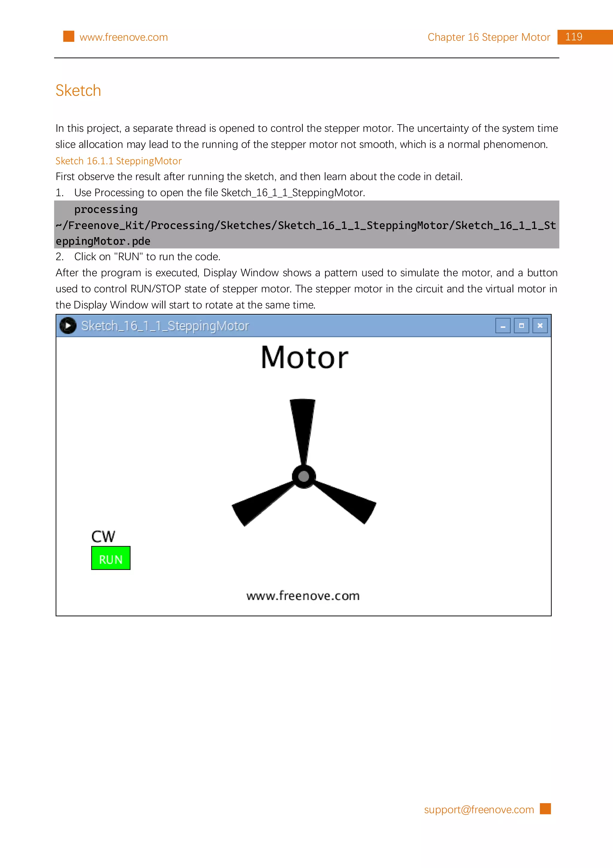
The stepper motor rotates clockwise at a fixed speed for a circle and then rotates counterclockwise for
another circle, which repeats in an endless loop. Clicking on the Button can change the state (start or stop)
of the stepper motor.
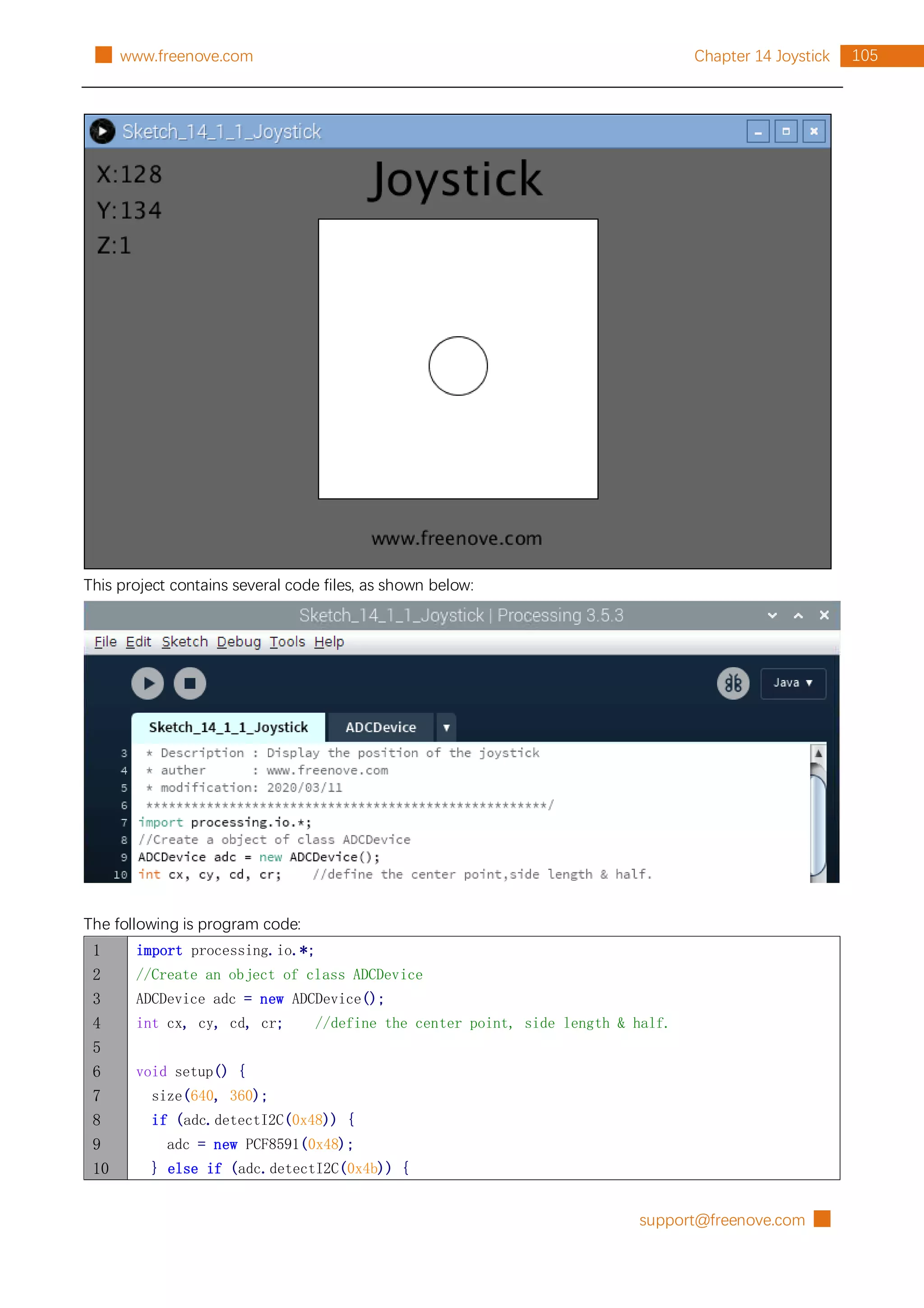
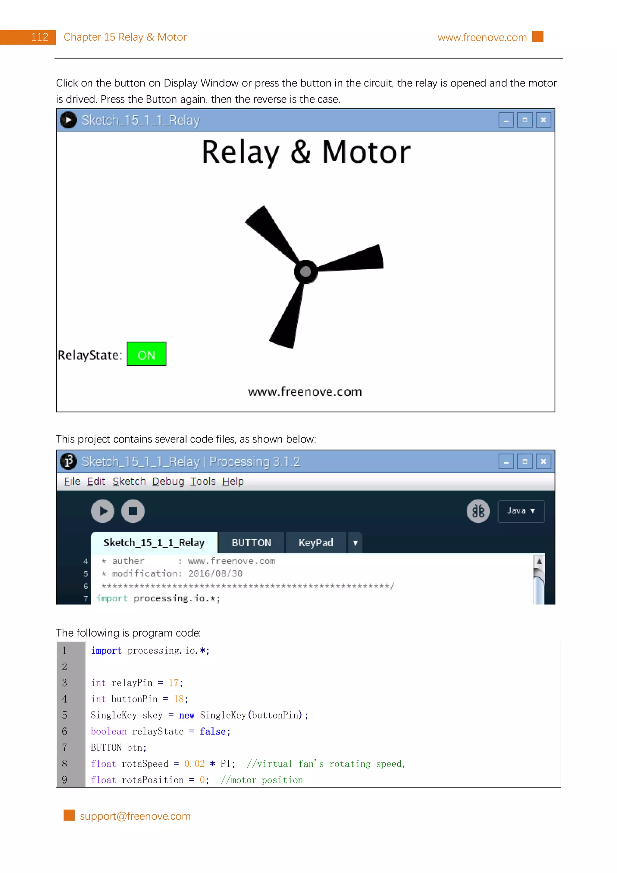
This project contains several code files, as shown below:
The following is program code:
1
2
3
4
5
6
7
8
import processing.io.*;
int[] pins = {18, 23, 24, 25}; //connect to motor phase A,B,C,D pins
BUTTON btn; //BUTTON Object, For controlling the direction of motor
SteppingMotor m = new SteppingMotor(pins);
float rotaSpeed = 0, rotaPosition = 0; //motor speed
boolean isMotorRun = true; //motor run/stop flag](https://image.slidesharecdn.com/processing-211120122651/75/Processing-language-124-2048.jpg)
![█ support@freenove.com
122 Chapter 16 Stepper Motor www.freenove.com █
53
54
55
56
57
58
59
60
61
62
63
64
65
66
67
68
69
70
71
72
73
74
75
76
77
78
79
80
81
82
83
84
85
86
87
88
89
90
for (int i=0; i<3; i++) {
arc(width/2, height/2, 200, 200, 2*i*PI/3+angle, (2*i+0.3)*PI/3+angle, PIE);
}
fill(0);
ellipse(width/2, height/2, 30, 30);
fill(128);
ellipse(width/2, height/2, 15, 15);
}
void exit() {
m.motorStop();
println("exit");
System.exit(0);
}
void mousePressed() {
if ((mouseY< btn.y+btn.h) && (mouseY>btn.y)
&& (mouseX< btn.x+btn.w) && (mouseX>btn.x)) { // the mouse clicks the button
if (isMotorRun) {
isMotorRun = false;
btn.setBgColor(255, 0, 0);
btn.setText("STOP");
m.motorStop();
} else {
isMotorRun = true;
btn.setBgColor(0, 255, 0);
btn.setText("RUN");
m.motorRestart();
}
}
}
void titleAndSiteInfo() {
fill(0);
textAlign(CENTER); //set the text centered
textSize(40); //set text size
text("Motor", width / 2, 40); //title
textSize(16);
text("www.freenove.com", width / 2, height - 20); //site
}
First define 4 GPIOs connected to the motor, the BUTTON class object and SteppingMotor class object.
int[] pins = {18, 23, 24, 25}; //connect to motor phase A,B,C,D pins
BUTTON btn; //BUTTON Object, For controlling the direction of motor
SteppingMotor m = new SteppingMotor(pins);](https://image.slidesharecdn.com/processing-211120122651/75/Processing-language-126-2048.jpg)
![█ support@freenove.com
124 Chapter 16 Stepper Motor www.freenove.com █
}
Finally draws the virtual fan.
drawFan(rotaPosition);
Reference
class SteppinMotor
This is a custom class that defines some methods to drive the four-phase stepper motor.
public SteppingMotor(int[] mPins)
Constructor. The parameter represents the GPIO pin connected to the stepper motor.
public void motorStart()
Start a stepper motor thread, then the thread is in the state of waiting, waiting for a notification to wake it
up.
public void moveSteps(int idir, int ims, int isteps)
Used to drive stepper motor to rotate, the parameter “idir” indicates the direction that can be set as
CW/CCW. The parameter “ims” is the delay (with unit ms) between each two steps of stepper motor. The
higher the value of “ims”, the lower the speed of stepper motor. Parameter “isteps” specifies the number
of rotating steps of the stepper motor. As for four-phase stepper motor, four steps make a cycle, if set
isteps=1, which means to specify the stepping motor to rotate four steps.
public void motorStop()
Stop stepper motor.
public void motorRestart()
Restart to drive stepper motor.](https://image.slidesharecdn.com/processing-211120122651/75/Processing-language-128-2048.jpg)

![█ support@freenove.com
130 Chapter 17 Matrix Keypad www.freenove.com █
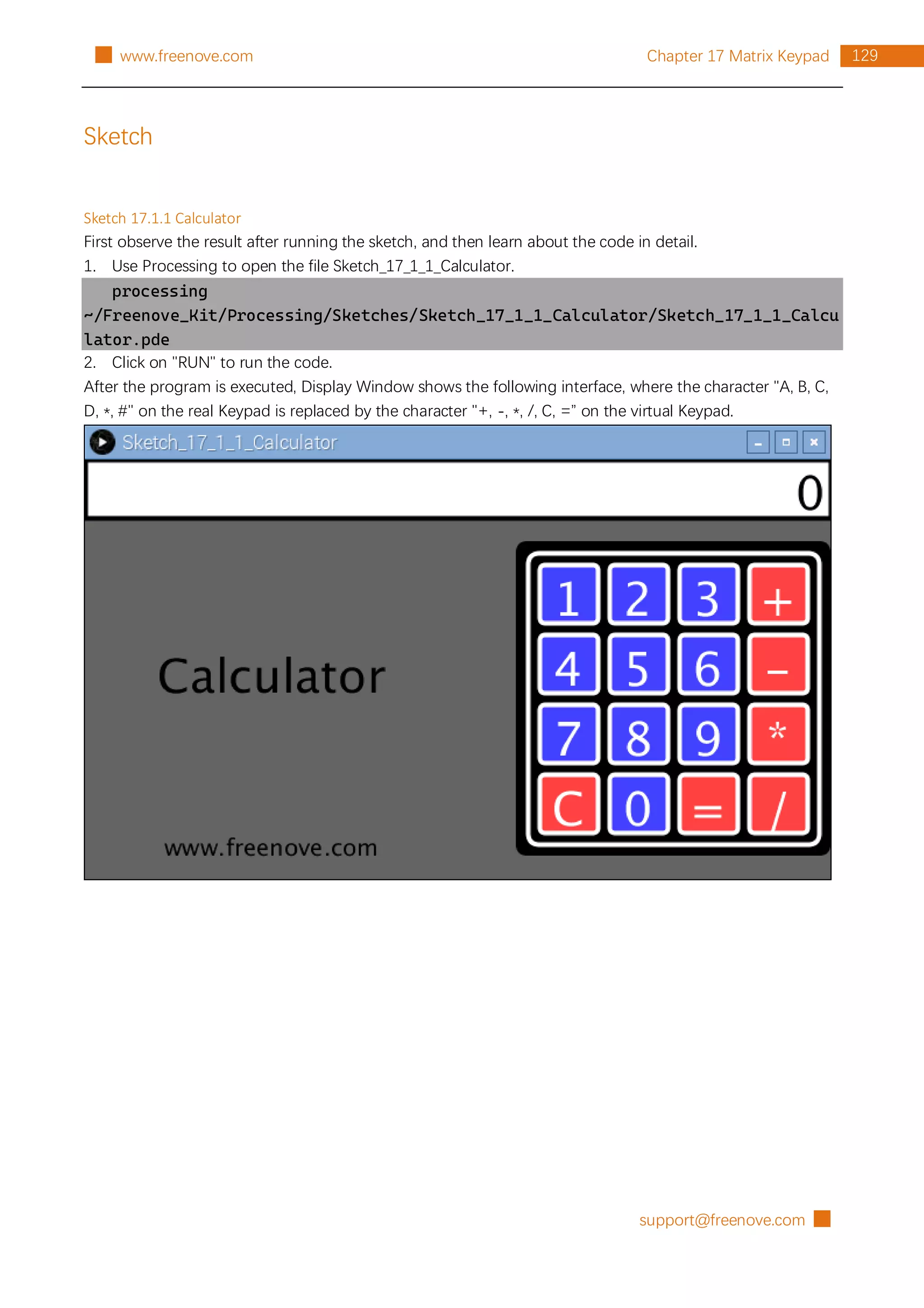
Calculator achieves the basic operation of add, subtract, multiply and divide. Button "C" means Clear,
namely, clear the current content. When a button is pressed, the color of the corresponding button on the
virtual keyboard will be turned into green, which indicates that the button is pressed.
This project contains several code files, as shown below:
The following is program code:
1
2
3
4
5
6
7
8
9
10
import processing.io.*;
final static char[] keys = { //key code
'1', '2', '3', '+',
'4', '5', '6', '-',
'7', '8', '9', '*',
'C', '0', '=', '/' };
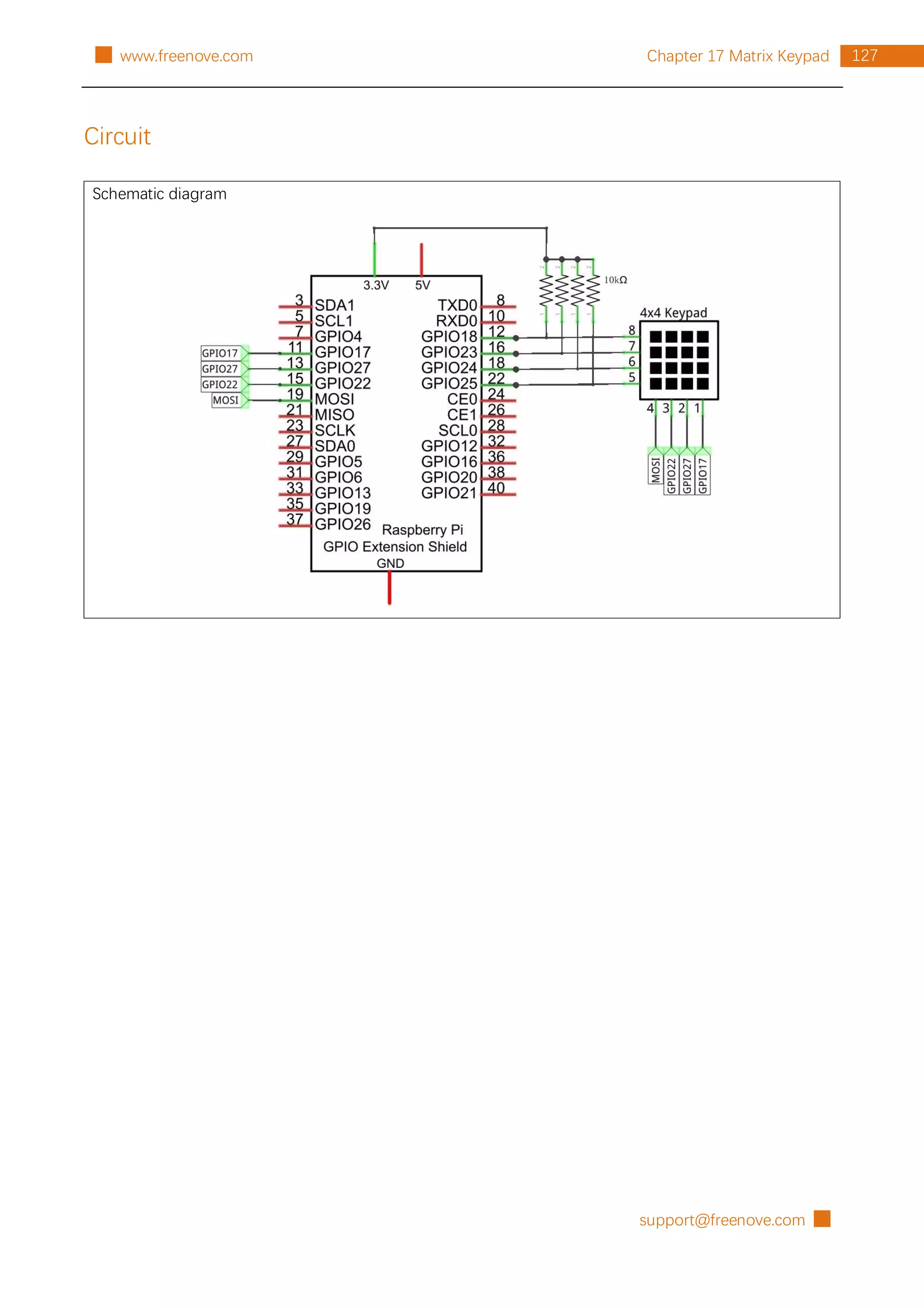
final int[] rowsPins = {18, 23, 24, 25}; //Connect to the row pinouts of the keypad
final int[] colsPins = {10, 22, 27, 17}; //Connect to the column pinouts of the keypad
Keypad kp = new Keypad(keys, rowsPins, colsPins); //class object](https://image.slidesharecdn.com/processing-211120122651/75/Processing-language-134-2048.jpg)
![support@freenove.com █
131
Chapter 17 Matrix Keypad
█ www.freenove.com
11
12
13
14
15
16
17
18
19
20
21
22
23
24
25
26
27
28
29
Calculator cc = new Calculator(kp); //class Object
void setup() {
size(640, 360);
}
void draw() {
background(102);
titleAndSiteInfo(); //Tile and site information
cc.process(); //Get key and processing
drawDisplay(cc.contentStr); //Draw display area and content
drawKeypad(width-kpSize, 70); //draw virtual Keypad
}
void titleAndSiteInfo() {
fill(0);
textAlign(CENTER); //set the text centered
textSize(40); //set text size
text("Calculator", width / 4, 200); //title
textSize(20);
text("www.freenove.com", width / 4, height - 20); //site
}
In the code, first define key code of the Keypad, and the GPIO connected to the Keypad. Then create a Keypad
class object based on the information, and finally create a Calculator class object according to the Keypad
class object.
final static char[] keys = { //key code
'1', '2', '3', '+',
'4', '5', '6', '-',
'7', '8', '9', '*',
'C', '0', '=', '/' };
final int[] rowsPins = {18, 23, 24, 25}; //Connect to the row pinouts of the keypad
final int[] colsPins = {10, 22, 27, 17}; //Connect to the column pinouts of the keypad
Keypad kp = new Keypad(keys, rowsPins, colsPins); //class object
Calculator cc = new Calculator(kp); //class object
In draw(), use cc.process() to obtain the key code of Keypad and for processing. And then draw the display
area and virtual Keypad.
void draw() {
background(102);
titleAndSiteInfo(); //Tile and site information
cc.process(); //Get key and processing
drawDisplay(cc.contentStr); //Draw display area and content
drawKeypad(width-kpSize, 70); //draw virtual Keypad
}](https://image.slidesharecdn.com/processing-211120122651/75/Processing-language-135-2048.jpg)
![█ support@freenove.com
132 Chapter 17 Matrix Keypad www.freenove.com █
Reference
void drawKeypad(int x, int y)
Used to draw a Keypad with (x, y) on the upper left corner.
void drawDisplay(String content)
The function at the top of the window to draw a calculator display area, and in the area of the right
alignment display content.
class Key
This is a custom class that defines the associated attribute owned by a key. There are only some member
variables and a constructor in this class.
class Keypad
This is a custom class that defines the methods to use keypad.
public Keypad(char[] usrKeyMap, int[] row_Pins, int[] col_Pins)
Constructor, the parameters are: key code of keyboard, row pins, column pins.
public char getKey()
Get the key code of the pressed key. If no key is pressed, the return value is '0'.
public void setDebounceTime(int ms)
Set the debounce time. And the default time is 10ms.
public void setHoldTime(int ms)
Set the time when the key holds stable state after pressed.
public boolean isPressed(char keyChar)
Judge wether the key with code "keyChar" is pressed.
public char waitForKey()
Wait for a key to be pressed, and return key code of the pressed key.
public int getState()
Get state of the keys.
boolean keyStateChanged()
Judge whether there is a change of key state, then return True or False.
class Calculator
This is a custom class that defines the rules and calculating methods of the calculator.
String contentStr = "";
Member variable that saves the current processing results of the calculator, which will be directly displayed
in the display area.
public Calculator(Keypad kp)
Constructor. the parameter is for the Keypad class object.
public void process()
Gets the key code of the key, and makes the corresponding judgment and processing. The Processing
results are stored in the member variable “contentStr”.
public double parse(String content)
This is the core of the calculator. It is to parse a string of four fundamental operations and return its double-
precision floating-point number equivalent.. For example, enter a string "1+2-3*4/5", then return value of
0.6.](https://image.slidesharecdn.com/processing-211120122651/75/Processing-language-136-2048.jpg)