SlideShare a Scribd company logo
1 of 4
Download to read offline
IJSRD - International Journal for Scientific Research & Development| Vol. 3, Issue 10, 2015 | ISSN (online): 2321-0613
All rights reserved by www.ijsrd.com 517
Compression Buckling Analysis of Vertical Tail Stiffened Panels.
Shaikh.Md.Furkhan1
Mr.Ambadas.Kadam2
1
P.G Student 2
Assistant Professor
1,2
Department of Machine Design
1,2
Visvsevaraya Technological University Regional Center, Kalaburagi
Abstract— Thin structural members are susceptible to
buckling under compression loading. Aircraft skin is always
thin irrespective of the size of the aircraft. Therefore, when
the skin undergoes compression, it is likely to buckle.
Vertical tail of the aircraft experiences bending, whenever
the rudder is deflected to achieve the yawing motion of the
aircraft. Side load will cause the bending of the vertical tail,
which introduces tension and compression stress field in the
two side skins respectively. This project includes the linear
static analysis of the vertical tail box structure and buckling
analysis of the stiffened panels undergoing compression. A
linear static buckling analysis of the vertical tail box
structure will be carried out to identify the most critical
panel. After that the critical panel is taken for buckling
analysis.
Key words: Vertical load, Stiffeners, Flight loads,
Compressive stress, tensile stress, Ribs, Stringers and
Buckling
I. INTRODUCTION
The airplane we are designing needs to have the required
strength and toughness to resists the extreme conditions. The
design must be such that if in a case one of the parts of the
airplane fails, the entire airplane shouldn’t fail. The
important parts of the airplane are the fuselage, the
empennage and the wings. The airframe is the load bearing
member of the parts which are subjected to forces. In the
case of old airplanes the skin is made from impregnated
linen which is not capable of transmitting any forces. In
modern day aircrafts we are using hollow parts instead of
solid sections because of the simple reason of weight
reduction. But in the process we are losing out stiffness. For
that purpose stiffeners are used. Skin and stingers acts as
stiffeners. Stiffeners are attached to the skin. Stingers are the
stiffening members that come in various cross sections and
serve various purposes. Sheet metals are used in preparing
the skin and are cheaper than other types of stingers. But
complicated stiffeners cannot be made using the sheet metal.
Stiffened panel is a panel used for the buckling analysis of
the structure at the local level.
II. OBJECTIVE OF THE WORK
“The buckling analysis is done for the vertical tail to
examine whether the tail buckles or not at the maximum
load. Further the buckling analysis is done for the stiffened
panels also”.
III. GEOMETRICAL SPECIFICATIONS OF VERTICAL TAIL
The aircraft considered in this project is the Cessna 206
Stationair which has seating capacity of 6 persons and the
load acting on the vertical of the aircraft is 3264 kgs. Spars
used here are of I section and thickness of 3mm, stingers
used here are of Z section and thickness of 2mm. The
thickness of skin and ribs are 2mm and 3mm respectively.
Rivets have a diameter of 5mm.
Fig. 1: Basic parts of the vertical tail.
1) VERTICAL TAIL
Length of the tail - 3662 mm.
Sweep angle - 30 degree.
Material used – aluminum 7075-T6.
2) RIBS
Cross section – NACA 0012 aerofoil.
Thickness – 5 mm.
3) SPARS
Cross section – I section.
Thickness– 3 mm.
4) STRINGERS
Cross Section - Z section.
Thickness - 2mm
Material
Young’s
modulus
E i n
(Gpa)
Poisson’s
ratio γ
Tensile
ultimate
stress σ t
in MPa
Tensile
yield
stress
σ y in
Mpa
Density
p in
kg/
m3
Aluminum
7075-T6
71.7 0.33 572 503 2780
Table 1: Mechanical Properties of Aluminum 7075-T6
Component Al Cr Cu Fe Mg Mn Si Ti Zn
Weight %
87.1-
91.4
0.18-
0.28
1.2-
2
Max
0.5
2.1-
2.9
Max
0.3
Max
0.4
Max
0.2
5.1-
6.1
Table 2: Composition of Aluminum 7075-T6.
IV. MESHING OF RIBS, SPARS, STINGERS & RIVETS
Ribs, Spars, Stingers are extracted and meshed separately
and all the quality parameters are checked. Rivets are made
to connect these parts with the skin. All the parts are now
posted and the completely meshed vertical tail before
analysis looks as below:
Compression Buckling Analysis of Vertical Tail Stiffened Panels.
(IJSRD/Vol. 3/Issue 10/2015/107)
All rights reserved by www.ijsrd.com 518
Fig. 2: Complete of Meshed Mail.
V. STRESS ANALYSIS OF VERTICAL TAIL (GLOBAL
ANALYSIS)
1) Length of each rib calculated from base to center of the
rib is as:
L1= 90.7 mm
L2= 333.23 mm
L3= 675.7 mm
L4= 1063.7 mm
L5= 1395.6 mm
L6= 1775.16 mm
L7= 2117.83 mm
L8= 2488.05 mm
L9= 2840.1 mm
L10= 3221.46 mm
L11= 3617.34 mm
Total length = 3662.2 mm
2) Load factor is calculated by dividing the corresponding
lift value from the chart to the sum of all lift values and
multiplied with total weight of the aircraft tail.
Load factor = (lift value) / (sum of lift) х weight of the
aircraft tail.
Load factor for 1st
rib = (0.6)/ (7.5) х 3264 = 261.12
Load factor for 2nd
rib = (0.8)/(7.5) х 3264 = 348.16
Load factor for 3rd
rib = (1.25)/(7.5) х 3264 = 544
Load factor for 4th
rib = (1.5)/(7.5) х 3264 = 652.8
Load factor for 5th
rib = (1.7)/(7.5) х 3264 = 739.84
Load factor for 6th
rib = (1.8)/(7.5) х 3264 = 783.36
Load factor for 7th
rib = (1.9)/(7.5) х 3264 = 826.88
Load factor for 8th
rib = (1.8)/(7.5) х 3264 = 783.36
Load factor for 9th
rib = (1.6)/(7.5) х 3264 = 696.32
Load factor for 10th
rib = (1.25)/(7.5) х 3264 = 544
Load factor for 11th
rib = (0)/(7.5) х 3264 = 0
3) Bending moment is calculated is as
follows:
BM = ∑ (load factor х length)
BM = (261.12 х 90.7) + (348.16 х 333.23) + (544 х
675.7) +
(652.8 х 1062.7) + (739.84 х 1395.6) + (783.86 х
1775.16) +
(826.88 х 2117.83) + (783.36 х 2488.05) + (696.32
х 2840.1)
+ (544 х 3221.46)
BM = 11055097.93 kgmm.
BM = 1.1 х 10^7 kgmm.
One end of the tail is fixed and the other end is
free, so the vertical tail acts as a cantilever beam. The
bottom end of the tail is fixed and the load is distributed
throughout the length of the vertical tail. Now do the linear
static analysis to get the stresses and deformation. In
analysis and in solution types check for linear static analysis
and run the software to get the stresses and deformations.
The average stress obtained 10- 15kg/mm² which is less
than the ultimate strength (35). Then we have to find the
buckling factor. For that change the solution type to
buckling and do the buckling analysis and get the buckling
factor. Buckling factor obtained was 0.08, which means that
the tail will buckle as the buckling factor is less than one. To
achieve that purpose rivets are added at the spar and then the
buckling analysis is done and now the buckling factor
obtained was 0.28547 which is still to be increased. Design
modification has to be carried out.
Fig. 3: Stress Analysis of Vertical Tail.
Fig. 4: Buckling Analysis Of Vertical Tail
Compression Buckling Analysis of Vertical Tail Stiffened Panels.
(IJSRD/Vol. 3/Issue 10/2015/107)
All rights reserved by www.ijsrd.com 519
VI. DESIGN MODIFICATIONS TO WITHSTAND COMPRESSION
BUCKLING
A. Local Analysis (Stiffened Panels):
Buckling factor for global analysis was less than 1 ,
therefore above mentioned modification has to be done i.e.
decrease the applied load ( Papplied ) or make the structure
more stiffer by increasing the thickness of the load bearing
members. In other words increasing the thickness of the skin
and ribs. Now we will concentrate on the buckling analysis
of stiffened panels. The stiffened panel comprises of skin
and stingers and did not include ribs because ribs functions
more as support to the structure. Top skin and stingers were
posted up to 4th rib from bottom and the loads were applied.
The root end is fixed and the load is applied on the top end.
Loads are calculated using the marker stresses. Marker
stresses are obtained as, in results go to create and then
marker and select stress tensor. In target entity select
elements. In display attributes change label style to fixed. In
plot options change it to global and apply.
1) Marker Stresses for Skin:
1.2 + 1.1 + 1.1 + 1.2 + 1.4 + 1.6 + 2+ 3 + 1.3 + 5.2 + 2.5 +
4.4 + 2.7 + 4.4 + 2.7 +2.1 + 1.6 + 1.4 +1.2 + 1.1 + 1.1 + 1.4
+ 2.1 + 1.5 + 1.9 + 2.6 + 1.8 + 1.4 + 1.6+ 1.7+ 1.7 + 1.7 +
1.6 + 1.5 + 1.1 + 1.6 + 1.9 + 2.6 + 2.4 + 2.2+ 2.5 + 2.5 +
2.5+ 2.4 + 2.2 + 2+ 1.4 + 1.6 + 1.6+ 2.4 + 2.5 +2.5 + 2.9 +
2.9 + 2.8 + 2.6 + 2.5 + 2.4 + 2.5 + 3.3 + 55 + 23
= 197.5 kg/mm².
Average stresses for skin = 197.5 / 60 = 3.292 kg/mm²
Area = (width) х (thickness)
= 1133.6678 х 3
= 3401 mm²
Load = (stress) х (area)
= 3.292 х 3401
= 11196.09 kg
Marker stresses for stingers: 0.09 + 0.16 + 0.08+ 0.05
= 0.38 kg/mm².
Average stress for stingers = 0.38 / 4
= 0.095 kg/mm²
Area = (width) х (thickness)
= 917.3 х = 1834.6 mm²
Load = (stress) х (area)
= 0.095 х 1834.6
= 174.287 kg
Load of 11196.09 kg and 174.287 kg has to be
applied at the skin and stingers of the stiffened panel
respectively. Linear static analysis is done and the results
are obtained. The stresses are well within the ultimate
stress and hence the structure is considered to be safe.
VII. RESULTS AND DISCUSSIONS
In order to increase the buckling factor and to make sure that
the tail doesn’t buckle under maximum applied load we
shall now consider the flat stiffened panels. The thickness of
the rib was increased from 3 mm to 5mm and the buckling
analysis done. The buckling factor obtained was 0.99. As
ribs act as support providing structure and in the stiffened
panels we have consider only skin and stingers and simulate
the ribs in this condition. For that the three sides of the skin
were simply supported and same loads were applied to the
skin and stingers with the root end being fixed. Linear static
analysis was carried out and the stress value was less than
the ultimate stress. Similarly buckling analysis was carried
out and the buckling factor obtained was 1.3596. Hence this
buckling factor was more than 1 and the stiffened panel is
safe under the given maximum applied loads and given
conditions.
Fig. 5: Stress Analysis of Stiffened Panels
Fig. 6: Buckling Analysis of Stiffened Panels.
VIII. CONCLUSION
As the buckling factor for global analysis was found to be
less than one, some modifications are to be done like
decreasing the load, increasing the thickness of ribs and
skin to make the structure stiffer and increasing the rivets
diameter etc. The modifications were suggested and the
concentration was on stiffened panels. In the stiffened
panels the section of the tail is considered with only skin and
stingers. The loads acting on the skin and stingers at these
sections have to be calculated. For that marker stresses are
found and then multiplying these stresses with the area, the
loads are found out. They are applied and the three sides of
the stiffened panels are simply supported to simulate the
support provided by the ribs. The linear static analysis and
buckling analysis were carried out and the buckling factor
was found out to be 1.3596. Hence we conclude that the
vertical tail is safe and will not buckle at the maximum
applied loads. Further analysis can be done for the linear
static and buckling analysis of complete model i.e. global
analysis. Also the effect of loads due to the moment of the
Compression Buckling Analysis of Vertical Tail Stiffened Panels.
(IJSRD/Vol. 3/Issue 10/2015/107)
All rights reserved by www.ijsrd.com 520
rudder on the joints between vertical tail and other parts
which are connected to it can be carried as future work.
REFERENCES
[1] Daniel P. Raymer “Aircraft Design: a conceptual
approach” 2nd edition 1992.
[2] T.H.G.Megson “Aircraft Structural Analysis” 4th
edition 2007.
[3] E.F.Bruhn’s “Analysis and design of Aircraft
structure”, Professor of aeronautics and astronautics,
Purdue University, copyright 1973.
[4] S.Timosheknko “Strength of Materials Part-I
elementary theory and problems” 2nd edition.
[5] Michael Chun-yung Niu “Airframe Structural Design”,
Lockheed Aeronautical Systems Company Burbank,
California, 8th edition, January 1995.
[6] Gatewood.M “Virtual Principles in Aircraft Structures”,
1st edition 1989.
[7] Mohammad H Sadraey, “Aircraft Design: A System
Engineering Approach” Wiley publications, 2012.
[8] Alfred.C.Loos “Introduction to composite materials”
Michigan state university, MI 48824-1226.

More Related Content

What's hot

Prediction of Fatigue Life of Boom Nose End Casting Using Linear Elastic Frac...
Prediction of Fatigue Life of Boom Nose End Casting Using Linear Elastic Frac...Prediction of Fatigue Life of Boom Nose End Casting Using Linear Elastic Frac...
Prediction of Fatigue Life of Boom Nose End Casting Using Linear Elastic Frac...
IJERA Editor
 
Reg 162 note dr norizal
Reg 162 note dr norizalReg 162 note dr norizal
Reg 162 note dr norizal
aliah idris
 

What's hot (20)

Compression test verification_for_a_wood
Compression test verification_for_a_woodCompression test verification_for_a_wood
Compression test verification_for_a_wood
 
Performance Optimization of Tie rod using FEA
Performance Optimization of Tie rod using FEAPerformance Optimization of Tie rod using FEA
Performance Optimization of Tie rod using FEA
 
Project documents on weight optimization of lathe bed
Project documents on weight optimization of lathe bedProject documents on weight optimization of lathe bed
Project documents on weight optimization of lathe bed
 
Steel strucure lec # (21)
Steel strucure lec #  (21)Steel strucure lec #  (21)
Steel strucure lec # (21)
 
presentation on contact analysis of dovetail joint
presentation on contact analysis of dovetail jointpresentation on contact analysis of dovetail joint
presentation on contact analysis of dovetail joint
 
lab report structure deflection of cantilever
lab report structure deflection of cantileverlab report structure deflection of cantilever
lab report structure deflection of cantilever
 
Probabilistic Design Hollow of Airfoil Wing by Using Finite Element Method
Probabilistic Design Hollow of Airfoil Wing by Using Finite Element MethodProbabilistic Design Hollow of Airfoil Wing by Using Finite Element Method
Probabilistic Design Hollow of Airfoil Wing by Using Finite Element Method
 
Determination of Elastic Behavior of RCC Section by Experimentation and Valid...
Determination of Elastic Behavior of RCC Section by Experimentation and Valid...Determination of Elastic Behavior of RCC Section by Experimentation and Valid...
Determination of Elastic Behavior of RCC Section by Experimentation and Valid...
 
severe plastic deformation (An approach to refine micro-structure ,improve st...
severe plastic deformation (An approach to refine micro-structure ,improve st...severe plastic deformation (An approach to refine micro-structure ,improve st...
severe plastic deformation (An approach to refine micro-structure ,improve st...
 
Prediction of Fatigue Life of Boom Nose End Casting Using Linear Elastic Frac...
Prediction of Fatigue Life of Boom Nose End Casting Using Linear Elastic Frac...Prediction of Fatigue Life of Boom Nose End Casting Using Linear Elastic Frac...
Prediction of Fatigue Life of Boom Nose End Casting Using Linear Elastic Frac...
 
weight optimization of lathe bed using FEA
weight optimization of lathe bed using FEAweight optimization of lathe bed using FEA
weight optimization of lathe bed using FEA
 
Probabilistic Design of Hollow Circular Composite Structure by using Finite E...
Probabilistic Design of Hollow Circular Composite Structure by using Finite E...Probabilistic Design of Hollow Circular Composite Structure by using Finite E...
Probabilistic Design of Hollow Circular Composite Structure by using Finite E...
 
Forming Limit Prediction of High Tensile Strength Steel using FEA Simulation
Forming Limit Prediction of High Tensile Strength Steel using FEA SimulationForming Limit Prediction of High Tensile Strength Steel using FEA Simulation
Forming Limit Prediction of High Tensile Strength Steel using FEA Simulation
 
Probabilistic design and random optimization of hollow rectangular composite ...
Probabilistic design and random optimization of hollow rectangular composite ...Probabilistic design and random optimization of hollow rectangular composite ...
Probabilistic design and random optimization of hollow rectangular composite ...
 
Finite Element Analysis of Roll Cage
Finite Element Analysis of Roll CageFinite Element Analysis of Roll Cage
Finite Element Analysis of Roll Cage
 
Reg 162 note dr norizal
Reg 162 note dr norizalReg 162 note dr norizal
Reg 162 note dr norizal
 
C09 m-403032016 som
C09 m-403032016 somC09 m-403032016 som
C09 m-403032016 som
 
Study of relation between grain size and mechanical properties
Study of relation between grain size and mechanical propertiesStudy of relation between grain size and mechanical properties
Study of relation between grain size and mechanical properties
 
Opti 222 w4
Opti 222 w4Opti 222 w4
Opti 222 w4
 
Ultimate strength
Ultimate strengthUltimate strength
Ultimate strength
 

Similar to Compression Buckling Analysis of Vertical Tail Stiffened Panels

Design, Analysis and Testing of Wing Spar for Optimum Weight
Design, Analysis and Testing of Wing Spar for Optimum WeightDesign, Analysis and Testing of Wing Spar for Optimum Weight
Design, Analysis and Testing of Wing Spar for Optimum Weight
RSIS International
 
TheFeatherShaft-EstelleandKeenan
TheFeatherShaft-EstelleandKeenanTheFeatherShaft-EstelleandKeenan
TheFeatherShaft-EstelleandKeenan
Keenan Finney
 
FEM_Modeling_Project_Evaluation of a Steel Pulley and Shaft Design
FEM_Modeling_Project_Evaluation of a Steel Pulley and Shaft DesignFEM_Modeling_Project_Evaluation of a Steel Pulley and Shaft Design
FEM_Modeling_Project_Evaluation of a Steel Pulley and Shaft Design
Mehmet Bariskan
 
ME 372 Final Project
ME 372 Final ProjectME 372 Final Project
ME 372 Final Project
Daniel Ramos
 
finalreportedit.docx
finalreportedit.docxfinalreportedit.docx
finalreportedit.docx
ChenXi Liu
 

Similar to Compression Buckling Analysis of Vertical Tail Stiffened Panels (20)

Design and Linear Static Analysis of Transport Aircraft Vertical Tail for Dif...
Design and Linear Static Analysis of Transport Aircraft Vertical Tail for Dif...Design and Linear Static Analysis of Transport Aircraft Vertical Tail for Dif...
Design and Linear Static Analysis of Transport Aircraft Vertical Tail for Dif...
 
gantry girders in india
gantry girders in indiagantry girders in india
gantry girders in india
 
E0314033040
E0314033040E0314033040
E0314033040
 
International Journal of Computational Engineering Research(IJCER)
International Journal of Computational Engineering Research(IJCER)International Journal of Computational Engineering Research(IJCER)
International Journal of Computational Engineering Research(IJCER)
 
Final presentation
Final presentationFinal presentation
Final presentation
 
IRJET-Finite Element Analysis of Seat Belt Buckle Assembly
IRJET-Finite Element Analysis of Seat Belt Buckle AssemblyIRJET-Finite Element Analysis of Seat Belt Buckle Assembly
IRJET-Finite Element Analysis of Seat Belt Buckle Assembly
 
Design, Analysis and Testing of Wing Spar for Optimum Weight
Design, Analysis and Testing of Wing Spar for Optimum WeightDesign, Analysis and Testing of Wing Spar for Optimum Weight
Design, Analysis and Testing of Wing Spar for Optimum Weight
 
TheFeatherShaft-EstelleandKeenan
TheFeatherShaft-EstelleandKeenanTheFeatherShaft-EstelleandKeenan
TheFeatherShaft-EstelleandKeenan
 
FEM_Modeling_Project_Evaluation of a Steel Pulley and Shaft Design
FEM_Modeling_Project_Evaluation of a Steel Pulley and Shaft DesignFEM_Modeling_Project_Evaluation of a Steel Pulley and Shaft Design
FEM_Modeling_Project_Evaluation of a Steel Pulley and Shaft Design
 
Analysis of stiffened isotropic and composite plate
Analysis of stiffened isotropic and composite plateAnalysis of stiffened isotropic and composite plate
Analysis of stiffened isotropic and composite plate
 
FORCES AND DEFLECTION OF COIL SPRINGS
FORCES AND DEFLECTION OF COIL SPRINGSFORCES AND DEFLECTION OF COIL SPRINGS
FORCES AND DEFLECTION OF COIL SPRINGS
 
Determination of Stress Intensity Factor for a Crack Emanating From a Rivet ...
Determination of Stress Intensity Factor for a Crack Emanating  From a Rivet ...Determination of Stress Intensity Factor for a Crack Emanating  From a Rivet ...
Determination of Stress Intensity Factor for a Crack Emanating From a Rivet ...
 
IRJET- Investigation of Stresses in Rear Half Axle of an Automobile
IRJET- Investigation of Stresses in Rear Half Axle of an AutomobileIRJET- Investigation of Stresses in Rear Half Axle of an Automobile
IRJET- Investigation of Stresses in Rear Half Axle of an Automobile
 
Structural Integrating of Ladder Type Heavy Load Automotive Chassis and its O...
Structural Integrating of Ladder Type Heavy Load Automotive Chassis and its O...Structural Integrating of Ladder Type Heavy Load Automotive Chassis and its O...
Structural Integrating of Ladder Type Heavy Load Automotive Chassis and its O...
 
ME 372 Final Project
ME 372 Final ProjectME 372 Final Project
ME 372 Final Project
 
Review of shaft failure in Coil Car Assembly
Review of shaft failure in Coil Car AssemblyReview of shaft failure in Coil Car Assembly
Review of shaft failure in Coil Car Assembly
 
Static analysis of portal axle output shaft using
Static analysis of portal axle output shaft usingStatic analysis of portal axle output shaft using
Static analysis of portal axle output shaft using
 
finalreportedit.docx
finalreportedit.docxfinalreportedit.docx
finalreportedit.docx
 
Kw3518711873
Kw3518711873Kw3518711873
Kw3518711873
 
Presentation
PresentationPresentation
Presentation
 

More from IJSRD

More from IJSRD (20)

#IJSRD #Research Paper Publication
#IJSRD #Research Paper Publication#IJSRD #Research Paper Publication
#IJSRD #Research Paper Publication
 
Maintaining Data Confidentiality in Association Rule Mining in Distributed En...
Maintaining Data Confidentiality in Association Rule Mining in Distributed En...Maintaining Data Confidentiality in Association Rule Mining in Distributed En...
Maintaining Data Confidentiality in Association Rule Mining in Distributed En...
 
Performance and Emission characteristics of a Single Cylinder Four Stroke Die...
Performance and Emission characteristics of a Single Cylinder Four Stroke Die...Performance and Emission characteristics of a Single Cylinder Four Stroke Die...
Performance and Emission characteristics of a Single Cylinder Four Stroke Die...
 
Preclusion of High and Low Pressure In Boiler by Using LABVIEW
Preclusion of High and Low Pressure In Boiler by Using LABVIEWPreclusion of High and Low Pressure In Boiler by Using LABVIEW
Preclusion of High and Low Pressure In Boiler by Using LABVIEW
 
Prevention and Detection of Man in the Middle Attack on AODV Protocol
Prevention and Detection of Man in the Middle Attack on AODV ProtocolPrevention and Detection of Man in the Middle Attack on AODV Protocol
Prevention and Detection of Man in the Middle Attack on AODV Protocol
 
Comparative Analysis of PAPR Reduction Techniques in OFDM Using Precoding Tec...
Comparative Analysis of PAPR Reduction Techniques in OFDM Using Precoding Tec...Comparative Analysis of PAPR Reduction Techniques in OFDM Using Precoding Tec...
Comparative Analysis of PAPR Reduction Techniques in OFDM Using Precoding Tec...
 
Evaluation the Effect of Machining Parameters on MRR of Mild Steel
Evaluation the Effect of Machining Parameters on MRR of Mild SteelEvaluation the Effect of Machining Parameters on MRR of Mild Steel
Evaluation the Effect of Machining Parameters on MRR of Mild Steel
 
Filter unwanted messages from walls and blocking nonlegitimate user in osn
Filter unwanted messages from walls and blocking nonlegitimate user in osnFilter unwanted messages from walls and blocking nonlegitimate user in osn
Filter unwanted messages from walls and blocking nonlegitimate user in osn
 
Keystroke Dynamics Authentication with Project Management System
Keystroke Dynamics Authentication with Project Management SystemKeystroke Dynamics Authentication with Project Management System
Keystroke Dynamics Authentication with Project Management System
 
Diagnosing lungs cancer Using Neural Networks
Diagnosing lungs cancer Using Neural NetworksDiagnosing lungs cancer Using Neural Networks
Diagnosing lungs cancer Using Neural Networks
 
A Survey on Sentiment Analysis and Opinion Mining
A Survey on Sentiment Analysis and Opinion MiningA Survey on Sentiment Analysis and Opinion Mining
A Survey on Sentiment Analysis and Opinion Mining
 
A Defect Prediction Model for Software Product based on ANFIS
A Defect Prediction Model for Software Product based on ANFISA Defect Prediction Model for Software Product based on ANFIS
A Defect Prediction Model for Software Product based on ANFIS
 
Experimental Investigation of Granulated Blast Furnace Slag ond Quarry Dust a...
Experimental Investigation of Granulated Blast Furnace Slag ond Quarry Dust a...Experimental Investigation of Granulated Blast Furnace Slag ond Quarry Dust a...
Experimental Investigation of Granulated Blast Furnace Slag ond Quarry Dust a...
 
Product Quality Analysis based on online Reviews
Product Quality Analysis based on online ReviewsProduct Quality Analysis based on online Reviews
Product Quality Analysis based on online Reviews
 
Solving Fuzzy Matrix Games Defuzzificated by Trapezoidal Parabolic Fuzzy Numbers
Solving Fuzzy Matrix Games Defuzzificated by Trapezoidal Parabolic Fuzzy NumbersSolving Fuzzy Matrix Games Defuzzificated by Trapezoidal Parabolic Fuzzy Numbers
Solving Fuzzy Matrix Games Defuzzificated by Trapezoidal Parabolic Fuzzy Numbers
 
Study of Clustering of Data Base in Education Sector Using Data Mining
Study of Clustering of Data Base in Education Sector Using Data MiningStudy of Clustering of Data Base in Education Sector Using Data Mining
Study of Clustering of Data Base in Education Sector Using Data Mining
 
Fault Tolerance in Big Data Processing Using Heartbeat Messages and Data Repl...
Fault Tolerance in Big Data Processing Using Heartbeat Messages and Data Repl...Fault Tolerance in Big Data Processing Using Heartbeat Messages and Data Repl...
Fault Tolerance in Big Data Processing Using Heartbeat Messages and Data Repl...
 
Investigation of Effect of Process Parameters on Maximum Temperature during F...
Investigation of Effect of Process Parameters on Maximum Temperature during F...Investigation of Effect of Process Parameters on Maximum Temperature during F...
Investigation of Effect of Process Parameters on Maximum Temperature during F...
 
Review Paper on Computer Aided Design & Analysis of Rotor Shaft of a Rotavator
Review Paper on Computer Aided Design & Analysis of Rotor Shaft of a RotavatorReview Paper on Computer Aided Design & Analysis of Rotor Shaft of a Rotavator
Review Paper on Computer Aided Design & Analysis of Rotor Shaft of a Rotavator
 
A Survey on Data Mining Techniques for Crime Hotspots Prediction
A Survey on Data Mining Techniques for Crime Hotspots PredictionA Survey on Data Mining Techniques for Crime Hotspots Prediction
A Survey on Data Mining Techniques for Crime Hotspots Prediction
 

Recently uploaded

Spellings Wk 4 and Wk 5 for Grade 4 at CAPS
Spellings Wk 4 and Wk 5 for Grade 4 at CAPSSpellings Wk 4 and Wk 5 for Grade 4 at CAPS
Spellings Wk 4 and Wk 5 for Grade 4 at CAPS
AnaAcapella
 

Recently uploaded (20)

Spellings Wk 4 and Wk 5 for Grade 4 at CAPS
Spellings Wk 4 and Wk 5 for Grade 4 at CAPSSpellings Wk 4 and Wk 5 for Grade 4 at CAPS
Spellings Wk 4 and Wk 5 for Grade 4 at CAPS
 
How to Manage Call for Tendor in Odoo 17
How to Manage Call for Tendor in Odoo 17How to Manage Call for Tendor in Odoo 17
How to Manage Call for Tendor in Odoo 17
 
80 ĐỀ THI THỬ TUYỂN SINH TIẾNG ANH VÀO 10 SỞ GD – ĐT THÀNH PHỐ HỒ CHÍ MINH NĂ...
80 ĐỀ THI THỬ TUYỂN SINH TIẾNG ANH VÀO 10 SỞ GD – ĐT THÀNH PHỐ HỒ CHÍ MINH NĂ...80 ĐỀ THI THỬ TUYỂN SINH TIẾNG ANH VÀO 10 SỞ GD – ĐT THÀNH PHỐ HỒ CHÍ MINH NĂ...
80 ĐỀ THI THỬ TUYỂN SINH TIẾNG ANH VÀO 10 SỞ GD – ĐT THÀNH PHỐ HỒ CHÍ MINH NĂ...
 
Beyond_Borders_Understanding_Anime_and_Manga_Fandom_A_Comprehensive_Audience_...
Beyond_Borders_Understanding_Anime_and_Manga_Fandom_A_Comprehensive_Audience_...Beyond_Borders_Understanding_Anime_and_Manga_Fandom_A_Comprehensive_Audience_...
Beyond_Borders_Understanding_Anime_and_Manga_Fandom_A_Comprehensive_Audience_...
 
Simple, Complex, and Compound Sentences Exercises.pdf
Simple, Complex, and Compound Sentences Exercises.pdfSimple, Complex, and Compound Sentences Exercises.pdf
Simple, Complex, and Compound Sentences Exercises.pdf
 
Philosophy of china and it's charactistics
Philosophy of china and it's charactisticsPhilosophy of china and it's charactistics
Philosophy of china and it's charactistics
 
21st_Century_Skills_Framework_Final_Presentation_2.pptx
21st_Century_Skills_Framework_Final_Presentation_2.pptx21st_Century_Skills_Framework_Final_Presentation_2.pptx
21st_Century_Skills_Framework_Final_Presentation_2.pptx
 
Tatlong Kwento ni Lola basyang-1.pdf arts
Tatlong Kwento ni Lola basyang-1.pdf artsTatlong Kwento ni Lola basyang-1.pdf arts
Tatlong Kwento ni Lola basyang-1.pdf arts
 
Details on CBSE Compartment Exam.pptx1111
Details on CBSE Compartment Exam.pptx1111Details on CBSE Compartment Exam.pptx1111
Details on CBSE Compartment Exam.pptx1111
 
Understanding Accommodations and Modifications
Understanding  Accommodations and ModificationsUnderstanding  Accommodations and Modifications
Understanding Accommodations and Modifications
 
latest AZ-104 Exam Questions and Answers
latest AZ-104 Exam Questions and Answerslatest AZ-104 Exam Questions and Answers
latest AZ-104 Exam Questions and Answers
 
On National Teacher Day, meet the 2024-25 Kenan Fellows
On National Teacher Day, meet the 2024-25 Kenan FellowsOn National Teacher Day, meet the 2024-25 Kenan Fellows
On National Teacher Day, meet the 2024-25 Kenan Fellows
 
SOC 101 Demonstration of Learning Presentation
SOC 101 Demonstration of Learning PresentationSOC 101 Demonstration of Learning Presentation
SOC 101 Demonstration of Learning Presentation
 
Towards a code of practice for AI in AT.pptx
Towards a code of practice for AI in AT.pptxTowards a code of practice for AI in AT.pptx
Towards a code of practice for AI in AT.pptx
 
Sensory_Experience_and_Emotional_Resonance_in_Gabriel_Okaras_The_Piano_and_Th...
Sensory_Experience_and_Emotional_Resonance_in_Gabriel_Okaras_The_Piano_and_Th...Sensory_Experience_and_Emotional_Resonance_in_Gabriel_Okaras_The_Piano_and_Th...
Sensory_Experience_and_Emotional_Resonance_in_Gabriel_Okaras_The_Piano_and_Th...
 
This PowerPoint helps students to consider the concept of infinity.
This PowerPoint helps students to consider the concept of infinity.This PowerPoint helps students to consider the concept of infinity.
This PowerPoint helps students to consider the concept of infinity.
 
COMMUNICATING NEGATIVE NEWS - APPROACHES .pptx
COMMUNICATING NEGATIVE NEWS - APPROACHES .pptxCOMMUNICATING NEGATIVE NEWS - APPROACHES .pptx
COMMUNICATING NEGATIVE NEWS - APPROACHES .pptx
 
Food safety_Challenges food safety laboratories_.pdf
Food safety_Challenges food safety laboratories_.pdfFood safety_Challenges food safety laboratories_.pdf
Food safety_Challenges food safety laboratories_.pdf
 
General Principles of Intellectual Property: Concepts of Intellectual Proper...
General Principles of Intellectual Property: Concepts of Intellectual  Proper...General Principles of Intellectual Property: Concepts of Intellectual  Proper...
General Principles of Intellectual Property: Concepts of Intellectual Proper...
 
Accessible Digital Futures project (20/03/2024)
Accessible Digital Futures project (20/03/2024)Accessible Digital Futures project (20/03/2024)
Accessible Digital Futures project (20/03/2024)
 

Compression Buckling Analysis of Vertical Tail Stiffened Panels

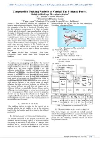
  • 1. IJSRD - International Journal for Scientific Research & Development| Vol. 3, Issue 10, 2015 | ISSN (online): 2321-0613 All rights reserved by www.ijsrd.com 517 Compression Buckling Analysis of Vertical Tail Stiffened Panels. Shaikh.Md.Furkhan1 Mr.Ambadas.Kadam2 1 P.G Student 2 Assistant Professor 1,2 Department of Machine Design 1,2 Visvsevaraya Technological University Regional Center, Kalaburagi Abstract— Thin structural members are susceptible to buckling under compression loading. Aircraft skin is always thin irrespective of the size of the aircraft. Therefore, when the skin undergoes compression, it is likely to buckle. Vertical tail of the aircraft experiences bending, whenever the rudder is deflected to achieve the yawing motion of the aircraft. Side load will cause the bending of the vertical tail, which introduces tension and compression stress field in the two side skins respectively. This project includes the linear static analysis of the vertical tail box structure and buckling analysis of the stiffened panels undergoing compression. A linear static buckling analysis of the vertical tail box structure will be carried out to identify the most critical panel. After that the critical panel is taken for buckling analysis. Key words: Vertical load, Stiffeners, Flight loads, Compressive stress, tensile stress, Ribs, Stringers and Buckling I. INTRODUCTION The airplane we are designing needs to have the required strength and toughness to resists the extreme conditions. The design must be such that if in a case one of the parts of the airplane fails, the entire airplane shouldn’t fail. The important parts of the airplane are the fuselage, the empennage and the wings. The airframe is the load bearing member of the parts which are subjected to forces. In the case of old airplanes the skin is made from impregnated linen which is not capable of transmitting any forces. In modern day aircrafts we are using hollow parts instead of solid sections because of the simple reason of weight reduction. But in the process we are losing out stiffness. For that purpose stiffeners are used. Skin and stingers acts as stiffeners. Stiffeners are attached to the skin. Stingers are the stiffening members that come in various cross sections and serve various purposes. Sheet metals are used in preparing the skin and are cheaper than other types of stingers. But complicated stiffeners cannot be made using the sheet metal. Stiffened panel is a panel used for the buckling analysis of the structure at the local level. II. OBJECTIVE OF THE WORK “The buckling analysis is done for the vertical tail to examine whether the tail buckles or not at the maximum load. Further the buckling analysis is done for the stiffened panels also”. III. GEOMETRICAL SPECIFICATIONS OF VERTICAL TAIL The aircraft considered in this project is the Cessna 206 Stationair which has seating capacity of 6 persons and the load acting on the vertical of the aircraft is 3264 kgs. Spars used here are of I section and thickness of 3mm, stingers used here are of Z section and thickness of 2mm. The thickness of skin and ribs are 2mm and 3mm respectively. Rivets have a diameter of 5mm. Fig. 1: Basic parts of the vertical tail. 1) VERTICAL TAIL Length of the tail - 3662 mm. Sweep angle - 30 degree. Material used – aluminum 7075-T6. 2) RIBS Cross section – NACA 0012 aerofoil. Thickness – 5 mm. 3) SPARS Cross section – I section. Thickness– 3 mm. 4) STRINGERS Cross Section - Z section. Thickness - 2mm Material Young’s modulus E i n (Gpa) Poisson’s ratio γ Tensile ultimate stress σ t in MPa Tensile yield stress σ y in Mpa Density p in kg/ m3 Aluminum 7075-T6 71.7 0.33 572 503 2780 Table 1: Mechanical Properties of Aluminum 7075-T6 Component Al Cr Cu Fe Mg Mn Si Ti Zn Weight % 87.1- 91.4 0.18- 0.28 1.2- 2 Max 0.5 2.1- 2.9 Max 0.3 Max 0.4 Max 0.2 5.1- 6.1 Table 2: Composition of Aluminum 7075-T6. IV. MESHING OF RIBS, SPARS, STINGERS & RIVETS Ribs, Spars, Stingers are extracted and meshed separately and all the quality parameters are checked. Rivets are made to connect these parts with the skin. All the parts are now posted and the completely meshed vertical tail before analysis looks as below:
  • 2. Compression Buckling Analysis of Vertical Tail Stiffened Panels. (IJSRD/Vol. 3/Issue 10/2015/107) All rights reserved by www.ijsrd.com 518 Fig. 2: Complete of Meshed Mail. V. STRESS ANALYSIS OF VERTICAL TAIL (GLOBAL ANALYSIS) 1) Length of each rib calculated from base to center of the rib is as: L1= 90.7 mm L2= 333.23 mm L3= 675.7 mm L4= 1063.7 mm L5= 1395.6 mm L6= 1775.16 mm L7= 2117.83 mm L8= 2488.05 mm L9= 2840.1 mm L10= 3221.46 mm L11= 3617.34 mm Total length = 3662.2 mm 2) Load factor is calculated by dividing the corresponding lift value from the chart to the sum of all lift values and multiplied with total weight of the aircraft tail. Load factor = (lift value) / (sum of lift) х weight of the aircraft tail. Load factor for 1st rib = (0.6)/ (7.5) х 3264 = 261.12 Load factor for 2nd rib = (0.8)/(7.5) х 3264 = 348.16 Load factor for 3rd rib = (1.25)/(7.5) х 3264 = 544 Load factor for 4th rib = (1.5)/(7.5) х 3264 = 652.8 Load factor for 5th rib = (1.7)/(7.5) х 3264 = 739.84 Load factor for 6th rib = (1.8)/(7.5) х 3264 = 783.36 Load factor for 7th rib = (1.9)/(7.5) х 3264 = 826.88 Load factor for 8th rib = (1.8)/(7.5) х 3264 = 783.36 Load factor for 9th rib = (1.6)/(7.5) х 3264 = 696.32 Load factor for 10th rib = (1.25)/(7.5) х 3264 = 544 Load factor for 11th rib = (0)/(7.5) х 3264 = 0 3) Bending moment is calculated is as follows: BM = ∑ (load factor х length) BM = (261.12 х 90.7) + (348.16 х 333.23) + (544 х 675.7) + (652.8 х 1062.7) + (739.84 х 1395.6) + (783.86 х 1775.16) + (826.88 х 2117.83) + (783.36 х 2488.05) + (696.32 х 2840.1) + (544 х 3221.46) BM = 11055097.93 kgmm. BM = 1.1 х 10^7 kgmm. One end of the tail is fixed and the other end is free, so the vertical tail acts as a cantilever beam. The bottom end of the tail is fixed and the load is distributed throughout the length of the vertical tail. Now do the linear static analysis to get the stresses and deformation. In analysis and in solution types check for linear static analysis and run the software to get the stresses and deformations. The average stress obtained 10- 15kg/mm² which is less than the ultimate strength (35). Then we have to find the buckling factor. For that change the solution type to buckling and do the buckling analysis and get the buckling factor. Buckling factor obtained was 0.08, which means that the tail will buckle as the buckling factor is less than one. To achieve that purpose rivets are added at the spar and then the buckling analysis is done and now the buckling factor obtained was 0.28547 which is still to be increased. Design modification has to be carried out. Fig. 3: Stress Analysis of Vertical Tail. Fig. 4: Buckling Analysis Of Vertical Tail
  • 3. Compression Buckling Analysis of Vertical Tail Stiffened Panels. (IJSRD/Vol. 3/Issue 10/2015/107) All rights reserved by www.ijsrd.com 519 VI. DESIGN MODIFICATIONS TO WITHSTAND COMPRESSION BUCKLING A. Local Analysis (Stiffened Panels): Buckling factor for global analysis was less than 1 , therefore above mentioned modification has to be done i.e. decrease the applied load ( Papplied ) or make the structure more stiffer by increasing the thickness of the load bearing members. In other words increasing the thickness of the skin and ribs. Now we will concentrate on the buckling analysis of stiffened panels. The stiffened panel comprises of skin and stingers and did not include ribs because ribs functions more as support to the structure. Top skin and stingers were posted up to 4th rib from bottom and the loads were applied. The root end is fixed and the load is applied on the top end. Loads are calculated using the marker stresses. Marker stresses are obtained as, in results go to create and then marker and select stress tensor. In target entity select elements. In display attributes change label style to fixed. In plot options change it to global and apply. 1) Marker Stresses for Skin: 1.2 + 1.1 + 1.1 + 1.2 + 1.4 + 1.6 + 2+ 3 + 1.3 + 5.2 + 2.5 + 4.4 + 2.7 + 4.4 + 2.7 +2.1 + 1.6 + 1.4 +1.2 + 1.1 + 1.1 + 1.4 + 2.1 + 1.5 + 1.9 + 2.6 + 1.8 + 1.4 + 1.6+ 1.7+ 1.7 + 1.7 + 1.6 + 1.5 + 1.1 + 1.6 + 1.9 + 2.6 + 2.4 + 2.2+ 2.5 + 2.5 + 2.5+ 2.4 + 2.2 + 2+ 1.4 + 1.6 + 1.6+ 2.4 + 2.5 +2.5 + 2.9 + 2.9 + 2.8 + 2.6 + 2.5 + 2.4 + 2.5 + 3.3 + 55 + 23 = 197.5 kg/mm². Average stresses for skin = 197.5 / 60 = 3.292 kg/mm² Area = (width) х (thickness) = 1133.6678 х 3 = 3401 mm² Load = (stress) х (area) = 3.292 х 3401 = 11196.09 kg Marker stresses for stingers: 0.09 + 0.16 + 0.08+ 0.05 = 0.38 kg/mm². Average stress for stingers = 0.38 / 4 = 0.095 kg/mm² Area = (width) х (thickness) = 917.3 х = 1834.6 mm² Load = (stress) х (area) = 0.095 х 1834.6 = 174.287 kg Load of 11196.09 kg and 174.287 kg has to be applied at the skin and stingers of the stiffened panel respectively. Linear static analysis is done and the results are obtained. The stresses are well within the ultimate stress and hence the structure is considered to be safe. VII. RESULTS AND DISCUSSIONS In order to increase the buckling factor and to make sure that the tail doesn’t buckle under maximum applied load we shall now consider the flat stiffened panels. The thickness of the rib was increased from 3 mm to 5mm and the buckling analysis done. The buckling factor obtained was 0.99. As ribs act as support providing structure and in the stiffened panels we have consider only skin and stingers and simulate the ribs in this condition. For that the three sides of the skin were simply supported and same loads were applied to the skin and stingers with the root end being fixed. Linear static analysis was carried out and the stress value was less than the ultimate stress. Similarly buckling analysis was carried out and the buckling factor obtained was 1.3596. Hence this buckling factor was more than 1 and the stiffened panel is safe under the given maximum applied loads and given conditions. Fig. 5: Stress Analysis of Stiffened Panels Fig. 6: Buckling Analysis of Stiffened Panels. VIII. CONCLUSION As the buckling factor for global analysis was found to be less than one, some modifications are to be done like decreasing the load, increasing the thickness of ribs and skin to make the structure stiffer and increasing the rivets diameter etc. The modifications were suggested and the concentration was on stiffened panels. In the stiffened panels the section of the tail is considered with only skin and stingers. The loads acting on the skin and stingers at these sections have to be calculated. For that marker stresses are found and then multiplying these stresses with the area, the loads are found out. They are applied and the three sides of the stiffened panels are simply supported to simulate the support provided by the ribs. The linear static analysis and buckling analysis were carried out and the buckling factor was found out to be 1.3596. Hence we conclude that the vertical tail is safe and will not buckle at the maximum applied loads. Further analysis can be done for the linear static and buckling analysis of complete model i.e. global analysis. Also the effect of loads due to the moment of the
  • 4. Compression Buckling Analysis of Vertical Tail Stiffened Panels. (IJSRD/Vol. 3/Issue 10/2015/107) All rights reserved by www.ijsrd.com 520 rudder on the joints between vertical tail and other parts which are connected to it can be carried as future work. REFERENCES [1] Daniel P. Raymer “Aircraft Design: a conceptual approach” 2nd edition 1992. [2] T.H.G.Megson “Aircraft Structural Analysis” 4th edition 2007. [3] E.F.Bruhn’s “Analysis and design of Aircraft structure”, Professor of aeronautics and astronautics, Purdue University, copyright 1973. [4] S.Timosheknko “Strength of Materials Part-I elementary theory and problems” 2nd edition. [5] Michael Chun-yung Niu “Airframe Structural Design”, Lockheed Aeronautical Systems Company Burbank, California, 8th edition, January 1995. [6] Gatewood.M “Virtual Principles in Aircraft Structures”, 1st edition 1989. [7] Mohammad H Sadraey, “Aircraft Design: A System Engineering Approach” Wiley publications, 2012. [8] Alfred.C.Loos “Introduction to composite materials” Michigan state university, MI 48824-1226.