1. 1
Table of Contents
Acknowledgement..............................................................................................................................4
The Need and Government Regulations:..............................................................................................5
Effluent Water Sampling as Drone Application:.................................................................................5
How is the sampling done?..............................................................................................................7
Issues with the reel and cable suspension method:...........................................................................7
Why the need to take many samples?..............................................................................................7
Canadian Aviation Regulations (CAR) Regarding the Drones we will receive ...........................................8
Design Requirement...........................................................................................................................8
Description of the major Drone Components .......................................................................................9
Motors:..........................................................................................................................................9
Propellers:......................................................................................................................................9
Camera:.........................................................................................................................................9
Guards:..........................................................................................................................................9
Landing Gear:.................................................................................................................................9
Our Drone Motor and its characteristics:............................................................................................10
Block Diagram:..............................................................................................................................11
Thrust Calculations For Our Motor:....................................................................................................12
Thrust from Scale Method:............................................................................................................12
Thrust from Dead Weight Method:................................................................................................12
Thrust from Load cell method........................................................................................................13
Thrust From Imperial Equation: .....................................................................................................14
Thrust using the central equation: .................................................................................................14
Wind Test Results and Analysis:.........................................................................................................15
Physical Phenomenon that our drone can encounter:.........................................................................19
Blade Flapping..............................................................................................................................19
Windmill Brake State.....................................................................................................................19
Rotor Craft Vortex Ring State:........................................................................................................19
Scheduling.......................................................................................................................................21
Gantt chart...................................................................................................................................22
Why didwe gowith this design, and were there alternatives? ............................................................24
LandingPad:.................................................................................................................................24
2. 2
Option 1: Flat Styrofoam LandingPad.........................................................................................24
Option 2: Styrofoam Water Skis .................................................................................................25
Option 3: 3D print landing base..................................................................................................25
Straw/Water Collection Reservoir:.................................................................................................26
One way check valve design ..........................................................................................................27
Option 1: Bottom hydraulic one-way valve, open top ..................................................................27
Option 2: Top-Side pneumatic one way valve, closed top.............................................................28
Option 3: Hybrid of Options 1 and 2 ...........................................................................................29
Valve Type Selection..................................................................................................................30
Simulation of our Model ...................................................................................................................32
Flow Simulation on One Way Valve................................................................................................32
Hydrostatic and Pressure Simulation on Landing Pad......................................................................33
Some of the problems with design implementation and how they were overcome:..............................35
Delayed Valve Shipment:...............................................................................................................35
Difficulty taking off from water with long straw:.............................................................................35
Water Proofing and Testing:..........................................................................................................35
What are the resources you used to implement your plan?.................................................................36
Looking Back at our Work .................................................................................................................37
Modifications to the electrical circuit? ...........................................................................................37
Could there have been better formulas which could have been used for a better analysis?...............37
Incorporating programming?.........................................................................................................37
Market Considerations......................................................................................................................37
The market:..................................................................................................................................37
Things toimprove before sending the drone to market:..................................................................38
The journey Experienced:..................................................................................................................39
References:......................................................................................................................................41
Appendix A: Solid Works Drawingsfor the Drone ...............................................................................42
Appendix B: Solidworks Drawings for 3D printed parts........................................................................48
Appendix C: What we got out of the project......................................................................................49
3. 3
List of Figures:
Figure 1-Different Sources of Polution Discharge..................................................................................5
Figure 2-Example of NPDE Regulation for battery manufacturing plant..................................................6
Figure 3-Equal Width Increment method .............................................................................................7
Figure 4-Motor...................................................................................................................................9
Figure 5-Propeller...............................................................................................................................9
Figure 6-Camera.................................................................................................................................9
Figure 7-Guard...................................................................................................................................9
Figure 8-Landing Gear.........................................................................................................................9
Figure 9-Electrical and Mechanical Circuit..........................................................................................10
Figure 10-Motor Block Diagram.........................................................................................................11
Figure 11-Thrust from Scale ..............................................................................................................12
Figure 12-Vortex Ring State...............................................................................................................20
Figure 13-Gantt Chart.......................................................................................................................22
Figure 14-Drone Water Collection Mechanism ...................................................................................23
Figure 15-Force Balance for Flat Sturofoam........................................................................................24
Figure 16-Styrofoam Ski Figure 17-Water Plane.................................................................................25
Figure 18-3D print landing base-........................................................................................................25
Figure 19-3D print the reservoir.........................................................................................................26
Figure 20-Bottom hydraulic one-way valve.........................................................................................27
Figure 21-Top-Side pneumatic one way valve, closed top....................................................................28
Figure 22-Valve Hybrid of Options 1 and 2 .........................................................................................29
Figure 23-Disc Valves........................................................................................................................30
Figure 24-Spring Valves.....................................................................................................................30
Figure 25-GravityValves....................................................................................................................31
Figure 26-Flow Simulation on One Way Valve.....................................................................................32
Figure 27-Hydrostatic and Pressure Simulation on Landing Pad...........................................................34
Figure 28-The journey Experienced....................................................................................................39
Figure 29-Water Testing....................................................................................................................40
List of Tables
Table 1-Experimentally obtainedw vs voltage....................................................................................11
Table 2-Thrust From Dead Weight Method ........................................................................................12
Table 3-Thrust From Load Cell Method ..............................................................................................13
Table 4-Lift and Drag Forces at Different Wind Speeds........................................................................15
Table 5-Lift and Drag Coefficients at different Wind Speeds and Angles of Attack.................................15
Table 6-List of Components and Description.......................................................................................23
Table 7-Density of Materials [9].........................................................................................................24
Table 8-Decision Matrix ....................................................................................................................31
Table 9-Estimated Drone Cost, accounting for these addition:.............................................................39
4. 4
Acknowledgement
The teamwouldlike toacknowledgeProfessorStiharu andthe MECH 390 Teachingassistantsforthe
opportunitytoworkon thisproject.Anyquestionsorconcernsthatthe teamhad were easilyand
readilytakencare of.The projectwouldnothave beenpossible withouthelpful consultingfromour
teachingassistantSowndhar Salaman anddesignandprojectinsightsfromourknowledgableprofessor.
The team had a lotof funwiththe projectand isnow verymuch lookingforwardtobringingthe skills
that we have learntto our Capstone project.
5. 5
The Need and Government Regulations:
Effluent Water Sampling as Drone Application:
The fresh water resources of the world are very scarce, and now with increasing world
population the value of fresh drinkable water is extremely high. The problem in the last decades,
is the fact that the fresh water rivers of North America are becoming more and more polluted,
and some of the reasons for this can be seen in the figure below. It is the responsibility of
government agencies such as the EPA, or Environment Canada to ensure companies do not
pollute the waters.
Figure 1-Different Sources of Polution Discharge
The application envisioned for our drone, is for it to collect effluent water samples according to
standards and regulations to be tested later on in the lab. Usually big plants in different industries
(pulp and paper, mining, food processing…) require a lot of water from a stream or river source.
This water passes through the various circuits in the plant, where it accumulates pollutants and is
then released back into the river. This discharged water is called effluent.
In the United States, any individual or entity discharging substances into US waters requires a
very specific permit. A special branch of the Environmental Protection Agency called National
Pollution Discharge Elimination (NPDE) is responsible for awarding permits, and making sure
that terms stated in the permit are met.[1] In Canada, a similar structure can be found.
6. 6
Once a permit is awarded, the guidelines of the NPDE are very detailed and specific to that
particular industry (Aluminum forming, Coal minig, Dairy Product Processing, and so on).[2]
This permit sets specific limits on things like, Biochemical Oxygen Demand (BOD), Total
Suspended Fluids (TSF), pH and also outlines how often samples should be taken to monitor for
the specific pollutants being discharged. The NPDE sends out inspectors to make sure companies
are following the regulations. Below is an example of standards for a battery manufacturing
plant:
Figure 2-Example of NPDE Regulation for battery manufacturing plant
7. 7
How is the sampling done?
The details of the sampling ie, how many samples to take, the volume, the depth to use all
depend on the characteristics of the stream being studied (flow rate, velocity, turbulence). One of
the most widespread sampling methods used in the industry today is called the Equal Width
Increment method (EWI). In this method, the cross section of the stream is essentially divided
into equally spaced out intervals. Samples are taken by lowering and raising a sampler through
the water column at the center of each interval, similar to the figure below:
Figure 3-Equal Width Increment method
Issues with the reel and cable suspension method:
1) When sampling from a bridge, this can be very dangerous for the field personnel. He can
get distracted by the vehicles, leading to an accident.
2) When sampling a stream from a boat, this can also be dangerous, as the water conditions
can change abruptly making it very difficult to navigate safely back to shore.
Why the need to take many samples?
Simply put, we need to collect a lot of samples in order to get a representative sample. A
representative sample will give us better data, for better analysis. The US National field manual
for the collection of Water-Quality Data suggests to “collect a sufficient number of quality
control samples, appropriately distributed in time and space, to ensure the data quality
requirements are met”.[3] It is very unlikely that the water body studied will be homogenous.
This is why a single sample is not adequate enough to describe the physical and chemical
properties of the water along with the biological inhabitants.
8. 8
Canadian Aviation Regulations (CAR) Regarding the Drones we will
receive
In Canada Unmanned Aerial Vehicles are regulated by either transport Canada, the civil
regulatory authority, or the Department of National Defense being concerned with the military.
Civil aviation includes unmanned vehicles that operate under law enforcement, with commercial
purposes, surveillance purposes or scientific purposes (as in our case). Transport Canada uses a
detailed regulation document called the CAR which covers everything from flight permits,
airworthiness, noise compliance, flight testing and many other issues concerning manned and
unmanned aerial vehicles.[4]
The CAR makes it clear that there is a difference between a UAV and a model aircraft.
According to the CAR “If your aircraft weighs less than 35Kg and is used for recreational
purposes, you don’t need permission to fly”.[5] The aircraft or drone we will use for this project
is certainly under 35kg, allowing us to operate it without any certification. The CAR mentions
that if the operational purpose of the model aircraft are other than recreational, then it will be
considered a UAV and requires a Special Flight Operation Certificate (SPOC).
Even though we are exempt from certification such as the SPOC, Transport Canada mentions a
list of guideline that should be followed. These include, flying aircraft in good weather, keeping
aircraft in sight, making sure the aircraft is safe to fly and respecting the privacy of others. They
also suggest to not fly closer than 9km to any airport, closer than 150m from people, flying in
populated areas or within restricted airspaces.[5]
Design Requirement
Our intention with our design was to invent a much easier and safer method of water extraction
for effluent sampling. It was clear that the quadcopter presented a good opportunity to do this,
but the details for how this would be done is what is covered in the scope of this project. The
team’s first requirement was that no electrical components or separate controls would be needed
for the extraction. It is already difficult enough to pilot the quad and successfully land on water.
The components should be purely mechanical and the quad should collect water upon landing.
Initial ideas included pressure vessels and vacuum chambers that would engage the water
collection mechanism upon landing, but ultimately, the one-way valve design was chosen for its
simplicity and ability to perform as desired in the design. As long as the one way valve is pointed
down, it acts as a gravity valve which is very easy implemented on the quadcopter.
9. 9
Description of the major Drone Components
Motors:
There are 4 small DC motors on board the drone that power the 4
propellers. The motors appear to have a metal casing, with a metal
rotating rod, that connects to the pinion gear.
Propellers:
There are also 4 white propellers included in the package.
These propellers provide sufficient thrust for our drone to take
off.
Camera:
The Camera allows the user to take a live feed while controlling
the drone. This can be useful when piloting the drone from far
away.
Guards:
The guards provide safety against
the potentially dangerous propellers. They are also especially
useful in protecting the propeller blades against damage that they
can get from impact.
Landing Gear:
The landing gear provide stability upon landing of the quadcopter.
The plastic material of the landing gear allows for good shack
absorption.
Figure 4-Motor
Figure 5-Propeller
Figure 6-Camera
Figure 7-Guard
Figure 8-Landing Gear
10. 10
Our Drone Motor and its characteristics:
Derivation of the equations for the block diagram and transfer function:
A typical DC motor can be modelled with an internal resistance (R), inductance (L), a torque
resistance coefficient (b), a motor coefficient (K) and an internal voltage (Vb) all of which
powered by the applied voltage (V). These can be seen in the following figure:
Figure 9-Electrical and Mechanical Circuit
The DC motor can be modelled by writing the 2 electrical and mechanical differential equations,
transforming them to the Laplace domain and then combining them. The proceeding will
demonstrate this.
(1) Ki
(2)
KVb
(3)
kiVRi
dt
di
L )(
(4) kibJ
(5) )()()(2
sKIsbssJs
(6) )()()()( skssVsRIsLsI
(7)
)(
)()(
)(
RLs
sKssV
sI
(8) )()(
11
)( skssV
bJsLsR
K
s
s
(9)
2
))((
1
)(
)(
kLsRbJs
k
ssV
s
or
2
))(()(
)(
kLsRbJs
k
sV
s
(3) and(4) are respectivelythe
electricandmechanical equations
Assuming0I.C and Transforming
intoLaplace FrequencyDomain
Rearranging(6) and IsolatingI(s)
Putting(7) back into(5) and
rearranging.Forblockdiagram.
TransferFunction
12. 12
Thrust Calculations For Our Motor:
Thrust from Scale Method:
For this first part of the experiment, we had to measure
thrust by using a simple weighing scale. We first inverted
the drone and placed it on a circular tape disk. We then
zeroed the whole setup so that we can isolate only the
thrust force. The set up can be seen in figure 11. Applying
the maximum power from our controller, we constantly got
a reading of 126g. The thrust value (T) is given by
equation (1) below.
(1) NsmKgmgT 236.1)/81.9()126.0( 2
Thrust from Dead Weight Method:
Table 2-Thrust From Dead Weight Method
Weight
(g)
Weight in
(Kg)
Time in
(s)
Height in
(m)
Acceleration in
(m/s2)
Trust
(N)
29.80 0.0298 2.25 2.00 0.79 0.093077
32.00 0.0320 2.30 2.00 0.76 0.089074
32.50 0.0325 2.61 1.00 0.29 0.034586
48.90 0.0489 1.73 0.30 0.20 0.023616
Average thrust: 0.060088
In this second experiment, we attached weights of known values to our drone and took down the
time it took for the drone to reach a certain fixed height. We then varied these weights so that we
can get a more general picture. Using kinematic equations, we can obtain acceleration and then
convert it to thrust.
(2) 2
2
1
attvy o assuming vo=0 and rearranging for (a) gives (3)
(3) 2
2
t
y
a
Using equation (1) again and substituting m=mDrone+mweight gives us the thrust values shown in
table 1. Note that mDrone=0.088Kg.
Figure 11-Thrust from Scale
13. 13
Thrust from Load cell method
Total mass of the drone is 88 g.
Calibrating Weights (g) Charge (mV/V)
130 0.0641
146 0.0980
185 0.1562
209 0.1731
After calibrating load cell, connect drone to load cell, and measure values of Force (g). Convert
the Force (g) in to Thrust (N).
Table 3-Thrust From Load Cell Method
Test Force (g) Thrust (N)
1 36.48 0.358
2 37.51 0.368
3 41.07 0.403
4 45.21 0.444
14. 14
Sample Calculations
Conversion 1 N = 101.97 g (Force to Thrust)
Force measured 35.43 kg
Conversion: 36.48 g * (1N/101.97g) =0.358 N
Average Thrust:
0.358+0.368+0.403+0.444
4
= 0.393 N
Thrust From Imperial Equation:
Some of the known constants to plug into our thrust equation are:
- ρair: 1.23Kg/m3
- rrotor=0.065m
- Dmotor: 0.0025m
- Average rotation (n) from previous section: 34255.9rpm = 570.93 rev/s
- Average force from previous lab was: 0.0016Nm
- -Average current I= 2.1A
- Average voltage: 0.99V
- -A=π(0.065)2=0.01327
Thrust using the central equation:
2
2
2
2
V
Kq
AKt
T
also
I
Q
Kq
Plugging in these values we get the following:
NmT 1986.0
)1.2/0016.0(
)01.0)(01327.0)(23.1(*2
2
2
15. 15
Wind Test Results and Analysis:
Table 4-Lift and Drag Forces at Different Wind Speeds
Lift Drag
Wind speed (m/S) Wind speed (m/S)
Pitch
Angle 5 10 15 5 10 15
0 0.07 0.13 0.31 0.19 0.54 1.11
15 0.1 0.26 0.85 0.17 0.49 1.09
30 0.18 0.91 1.81 0.16 0.86 1.77
45 0.23 0.75 0.35 1.08
Table 1 above has the recorded data taken from the wind tunnel testing of the quadcopter. It was
taken in the aerodynamics class on the 10th floor of Hall Building. Based on theory discussed in
class, Coefficients of Lift and Drag could be calculated with the formulas below:
2
*2
VS
L
CL
2
*2
VS
D
CD
Where CL is Lift Coefficient, CD is the Drag Coefficient, L is Lift force, D is drag force, S is
surface area (8590.76mm2 from Solidworks CAD Model), ρ is air density (1.225 kg/m3), and V
is wind speed. This yields the following table:
Table 5-Lift and Drag Coefficients at different Wind Speeds and Angles of Attack
Lift Coefficients Drag Coefficients
Wind speed Wind speed
Pitch
Angle 5 10 15 5 10 15
0 0.532319 0.247078 0.261935 1.444455 1.026323 0.937658
15 0.760456 0.494156 0.718209 1.292407 0.931293 0.920764
30 1.368821 1.729545 1.529362 1.216383 1.634515 1.495185
45 1.749049 1.425449 2.660838 2.052647
16. 16
To optimize thrust, one must maximize lift and keep drag to a minimum. To do this, a plot of Lift
Coefficients Vs Drag Coefficients must first be created. Below are these plots for the different
wind speeds.
0
0.5
1
1.5
2
2.5
3
0 5 10 15 20 25 30 35 40 45 50
CLandCD
Angle of Attack
Angle of Attack vs( CL and CD) for 5 m/s
CL
CD
0
0.5
1
1.5
2
2.5
0 10 20 30 40 50
CLandCD
Angle of Attack
Angle of Attack vs (Cl and CD) for 10 m/s
CL
CD
0
0.2
0.4
0.6
0.8
1
1.2
1.4
1.6
1.8
0 5 10 15 20 25 30 35
CLandCD
Angle of Attack
Angle of Attack vs (Cl and CD) for 15m/s
Series1
Series2
17. 17
Data for 15m/s wind speed will be omitted from analysis. This is because the test prematurely
ended due to a malfunction of the drone’s propeller. Not enough data is attained to attain optimal
angle of attack. Drag and Lift curves do not reconverge. From the above data, it is apparent that
at angle of attack α of 30 degrees, there is optimal aerodynamic characteristics for flight. At
around 30 degrees, maximum CL, and a reasonable value for CD are attained.
According to support material thrust can be calculated through the following equation:
Optimal thrust can be calculated by substituting optimum values for V and α, parameters of the
wind tunnel test. All other parameters in the equation are constant properties of the system.
Constants a, b, c, R, and θ are characteristic geometry features of the rotor.
a is the lift curve slope(CL at 30o = 1.729)
b is the number of blades on the rotor(4*2 = 8)
c is the blade chord(20mm = 0.02m)
R is the radius of the rotor(70mm = 0.07m)
ω =VRcos(30) = 10*.07*0.866=0.606rad/s)
θ is the pitch angle (20o=0.349rad ).
For the case that the quadcopter is not in the vortex ring or windmill brake states, the induced
velocity (υ) is assumed to be zero.
18. 18
From our experiment we conclude that angle α of 30 degrees, and wind speed of 10m/s are
optimal. We were however not able to get the characteristic constants (a, b, c, R and θ) of the
rotor. If we get these values and plug them into the above equation, we can get a value for max
thrust and compare these values with the past assignment.
T =
(1.225∗1.729∗8∗.02∗(2.617)2∗(.02)3
2
(
0.349
3
+
102(0.349cos2(30)
2(0.6062)(.072)
+
10 sin(30)+0
2(0.606)(0.07)
)
T = (9.283 x 10⁻⁶)(0.116 + 20839.627 + 58.93)
T=0.194 Nm
This coincides very well with the thrust calculated for tutorial#4 using the central equation.
2
2
2
2
V
Kq
AKt
T
also
I
Q
Kq
Plugging in these values we get the following:
NmT 1986.0
)1.2/0016.0(
)01.0)(01327.0)(23.1(*2
2
2
This analysis of thrust however, does not take into consideration other mediums of energy
transfer of air to the rotor. It doesn’t consider factors such as blade flapping, vortex ring energy,
and windmill brake energy. These effects cause induced velocity (υ) not to be zero.
19. 19
Physical Phenomenon that our drone can encounter:
Blade Flapping
Blade flapping is related to the effect of dissymmetry of lift. Dissymmetry of lift occurs in all
rotorcraft systems. This happens when there is an uneven amount of lift on both the advancing
blade and the retreating blade. The advancing blade which travels in the same direction as the
relative wind will be subject to more lift as opposed to the retreating blade which is going against
the direction of relative wind.[6] Blade flapping counters the “dissymmetry” using the flapping
of each blade. The advancing blades will flap upwards because of the increased lift and the
retreating blades will flap downwards because of the decreased lift. The flapping will transfer
from one end to the other and change the angle of attack throughout the advancing blade and the
retreating blade. The various forces of lift will balance out on both sides, thus eliminating the
dissymmetry. The flapping of the blades might be a source of error for measurements of lift
taken during the wind tunnel experiment. The values taken for lift do not have an observable
constant relationship.
Windmill Brake State
During a fast descent, the quadcopters propellers experience an upward force of air causing them
to spin. As opposed to the vortex ring state, the rotors are actually extracting more energy than
they need for proper operation. This is very similar to the way that windmills turn due to wind
forces. This induces a force upward to the propeller slightly slowing down or “braking” its
descent. During the wind tunnel testing, the propellers of the drone would start spinning
whenever the pitch angle was greater than zero, this is due to the induced force acting at a
perpendicular angle to the propellers. The reason the propellers don’t spin at a pitch angle of zero
in the wind tunnel test is because the propellers are parallel to the wind flow, so they don’t
experience any force gradient. This is a factor that should be considered when analyzing the
wind tunnel data for the quadcopter.
Rotor Craft Vortex Ring State:
Vortex Ring State (VRS) is a physical phenomenon that effects the flight dynamics of rotor
aircraft. The phenomenon is characterized by a rapid drop in upward thrust caused by the
rotor.[7] Usually, the rotor’s fast spin causes a large amount of air to be pushed downward
causing the upward thrust that allows for flight. Because of the helicopter’s forward motion, the
vortices at the tip are left far behind the aircraft. When the rotor craft is moving horizontally with
slower velocities, or descending from a hovering state, these tip vortices are not convected away
fast enough, and start to interfere with flight.[8] This in essence is the cause of VRS. In this state,
even though the rotor is still pushing the air downwards, the tip vorticities cause a lot of that air
to go up on top of the rotor, pushing the rotorcraft downwards. Increasing the power of the rotor
only increases the VRS effect.
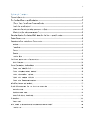
20. 20
The figure below is a good representation of the process. The blue arrows represent the air, the
strait arrow is the displaced air by the rotor down, and the curled vector represents the displaced
air filling up the space above the rotor blade.
Figure 12-Vortex Ring State
21. 21
Scheduling
The time management of the MECH 390 design project was done with the help of a Gantt chart.
The Gantt chart shown below demonstrates the planned duration of our activities and also shows
the actual duration of the activities. The team formed during our first tutorial had to be dissolved
during the second tutorial due to the fact that an extra student was added to our tutorial section.
This led us to form a new team, and brainstorm new ideas as of the second tutorial, which is
shown in the Gantt chart. The objective of our drone application was discussed during the second
tutorial and a list of the tasks necessary to complete this project was established. Once these
tasks had been determined, we estimated the duration of each task.
Looking at our Gantt, it can be seen that four of the planned tasks took more than the expected
time duration. Firstly, the research on the concept was initially expected to take one week’s time.
Due to the fact that all members of the groups were contributing their ideas, the team took the
time necessary to understand and evaluate each idea, causing the actual duration of this activity
to last two weeks instead of one. Another activity that took excess time to complete is the
printing of 3D components. No members of the team had previously had any experience in 3D
printing. Therefore, even though the team developed appropriate 2D drawings using SolidWorks
CAD software, there are several limitations to 3D printing. We had to do some research on the
limitations related to 3D printing and adjust our design accordingly. In addition, during the week
we submitted our files to print, most other teams had also submitted their requests, so there was a
delay in retrieving our part. We realized that this task could have been done in the earlier weeks
in order to avoid this delay. The tenth task on our list was making changes to our assembly
based on test results. This task involved more time than expected because the problem was
related to the material selection of our landing gear for which we were trying to research which
material would be optimal for this task. Lastly, the preparation of the report was delayed due to
the fact that we started it a week after we had originally planned to. The team was focusing on
the final assembly of the drone, which delayed the start of the final report.
Preparation for the final presentation was planned to start during week eleven, however, due to
our previous delays, the last activity on our Gantt chart was evidently delayed due to a chain
reaction of those delays. Overall, this project was conducted successfully with appropriate time
management. Although we only formed our team during the second tutorial, which was clearly a
disadvantage for us, we still managed to complete all our tasks and present our project within the
given time frame of the course. There are some delays that we could have foreseen and avoided
such as the 3D printing. On the other hand, other delays such as making changes based on test
results and preparing final report could have not been avoided. The important thing is that
everyone in the team was fully able to commit to completing each and every task, and when we
encountered delays the team all together put in more time for this project in order to be back on
track. This principle of our team allowed for us to successfully complete our project and create
an application for the drone that is fully functional.
23. 23
Designof Drone Water CollectionMechanism:
Figure 14-Drone Water Collection Mechanism
The drone water collection mechanism that we decided to go with is shown in the figure above.
This mechanism consists of 4 main components. A small description of each is given below:
Table 6-List of Components and Description
Component Description
Landing Pad Rectangular Styrofoam plate used by drone
for landing. Its good buoyant properties are
key for landing on water
Straw/ Reservoir This plastic reservoir serves to hold the water
collected
Cylindrical Disc This is the Styrofoam cylinder located on top
of the landing pad. It serves to relay the forces
upon impact to the drone.
One way valve This is the combination of the plastic pen cap,
rubber holder and spherical ball.
Cylinder
24. 24
Note, once can refer to Appendix A for details of drone drawings and assembles.
Why did we go with this design, and were there alternatives?
Landing Pad:
Option 1: Flat Styrofoam Landing Pad
The landing pad was made of Styrofoam and this is ideal for landing in water, because of its
buoyant properties.
The force analysis in the figure above is key to understanding why Styrofoam is a good choice
for floating on water. It can clearly be seen that an objects flotation is dependent on the
ρFluid/ρMaterial ratio. Materials with low ρMaterial material values are better for flotation. The
following table lists the density of some materials we were considering for the base. ABS plastic,
the main constituent of 3D printed part can be seen to have very large ρMaterial compared to
Styrofoam.
Table 7-Density of Materials [9]
Material Density (lb/cu-ft)
Styrofoam 2.3
Rubber 10
Polyethylene 58.37
Abs 65.7
gVFb submergedfluid
gVmgW FullSolidmaterial
Figure 15-Force Balance for
Flat Sturofoam
25. 25
Option 2: Styrofoam Water Skis
The other option that was looked at, was the possibility to land using hydro skis. This was
inspired from amphibious aircraft that use skis to land and take off from water.
Figure 16-Styrofoam Ski Figure 17-Water Plane
We decided to make our own set of Styrofoam landing skis, but upon testing, it was realized that
these interfered with the quadcopter’s lift. When we tested these, the air being pushed down by
the propellers, was finding its way to the back of the skis pushing the quadcopter like a boat.
Although aesthetically the design looked very nice, it did not serve the purpose aimed for.
Option 3: 3D print landing base
Before the force analysis on the previous page was carried out, an alternate design was proposed
and this was to 3D print the landing base. The final prodect would have looked something
similar to the figure below (Details of this design can be found in Appendix B). This alternative
was disgarded due to the following reasons:
1) Too heavy (56g compared to only 6 g for styrofoam landing pad)
2) With the volume proposed, this would take a long time to 3D print (30+ hours)
Figure 18-3D print landing base-
26. 26
Straw/Water Collection Reservoir:
The reservoir was first chosen to be a plastic straw because this is clearly a light way option.
From the thrust calculations and the tests we performed on the side, our drone could comfortably
lift 40-45g of payload. A plastic straw that weight only 2g was a perfect option.
The other option that was looked at, was to 3D print the reservoir. The design looked like the
figure below:
Figure 19-3D print the reservoir
This option was not that much better than the straw reservoir option. Yes it did look more
aesthetically pleasing, but it still weighed 16g compared to 2g. The more economy made in terms
of weight the easier it is to operate the drone. Keeping weight to a minimum was key in our
design strategy.
27. 27
One way check valve design
One way valves,sometimescalledcheckvalvesornon-returnvalveshave afew differentdesigns.These
designshave differentadvantagesanddisadvantagessoproperlyevaluatingwhichvalve design was
mostfeasible forourdesignprojectwasourteam’sbiggestchallenge.Aswell forourdesignproject
there were a fewdifferentone-wayvalve configurationsconsidered(i.e.positionof valve onreservoir,
not type of valve).
Valve ConfigurationOptions:
Option 1: Bottom hydraulic one-way valve, open top
Thisvalve configurationisprobablythe mostsimple of
the optionspresented,bothintermsof
understanding,and manufacturing.The basicprinciple
behindthisisdesignisthat hydrostaticpressure
(=ρgh) wouldcause watertoflow intothe tube
throughthe valve.Whenliftedoutof the water,water
wouldnotbe able to flow backout of the tube due to
gravity,because the valve isonlyone-way. This
configurationhasaverysimple assemblyprocedure,
few components,andthisisultimatelywhythe team
chose thisdesign.However,one issue withthisdesign
isthat the stockone-wayvalvesavailable onthe
markethad an openingpressure (sometimescalleda
breakingpressure) thatwasmostlikelytoohightobe
usedinthisdesign.Anyone-wayvalvealwaysneeds
to have a breakingpressure toproperlyfunction,
similartoan offsetvoltage foradiode.Ideal one way
vales,andideal diodes,simplydon’texistinthe real
world.Ourteam neededtomake ourowncustomone
wayvalve witha much lowerbreakingpressure.
Exactlyhow thiswas done will be coveredinthe valve
type selectionsection.
Figure 20-Bottom hydraulic one-wayvalve
28. 28
Option 2: Top-Side pneumatic one way valve, closed top
Thisis a slightlymore complicated
configuration.If Option1 hadn’tbeen
successful,thisseemedtobe the next
mostfeasible kindof configuration.The
conceptat work inthisdesignismuch
differentthenthe initialdesign.
Hydrostaticpressure doescause flowof
waterintothe reservoir,butthe reason
whywaterstays inthe reservoirismuch
different.The opentopin Option1 is
neededbecause forwatertoflowinto
the reservoir,airmustbe pushedout.
As well,fortowaterto fall outof the
reservoir,airmustcome back in.This
allowsairto be pushedoutof the
reservoirthroughthe top-sideone way
valve,butdoesnotallow airto come
back in,so the wateris notable to fall
out,eventhoughthe bottomis
completelyopen.Itwasthoughtthat
thisdesignwouldworkwell invertical
hover,butif angle of attack of quad was
not straight,waterwouldfall outof the
reservoir.Thismayhave beenworkable
if the bottomopeningwassmall enough
such that surface tensionof the water
wouldpreventitfromfallingout.The
designwasthoughtto have toomany
unknownstobe the firstideato explore
and test.
Figure 21-Top-Side pneumatic one way valve, closed top
29. 29
Option 3: Hybrid of Options 1 and 2
Figure 22-Valve Hybrid of Options 1 and 2
Thiswas the most complicatedoptionconsideredbythe team. The designwas thoughttohave the
reliabilityof option1,butthe lowbreakingpressure of option2.The ideabehindthisdesignisthatair
couldbe suckedout of the reservoirthroughthe toppneumaticvalve creatingavacuuminside,andthat
air wouldnotre-enterthe reservoirthrougheitherthe closedtoporthe bottomhydraulicvalve.If the
bottomhydraulicvalves’breakingpressure isonlyasmall amountgreaterthenatmosphericair
pressure,thenthe additionof the atmosphericpressuretothe hydrostaticpressure fromsubmersion
wouldopenthe hydraulicvalve allowingwatertoflow in,andof course not flow out.Thisdesign
seemedfeasible butrequiredwaytoomanycomponentstobe workingperfectlyintandem.Itwas
thoughtthat too manydesigniterationsforthisoptionwouldneedtobe conductedbefore findinga
workingprototype, andthiswassimplynotdoable becauseof budgetandtime constraints.
30. 30
Valve Type Selection
A fewdifferentmechanismshave beencreatedforthe one-waycheckvalve.The teamcreateda
decisionmatrix fordifferentvalve types.Propertiesof the valve consideredinorderof hightolow
priority were lowbreakingpressure,low sizeforintegrationintoassembly, low weight,andlow cost,
Disc Valves
Disc valvesare one wayvalvesthatuse a small metal
dischingedtoa wall asa one waygate forfluidflow.
Some use springsas addedbreakingpressure if a
highbreakingpressure isneeded.Theycome inall
differentkindsof materialsfromsteel toplastic.
Weightisnot an issue if the discvalve issmall and
made out of plastic,butsize and integrationinto
assemblywouldbe difficultaspropersealingand
placementwouldbe difficultforourdesign.[10]
Spring Valves
Springvalvesuse springstoforce a solidrubber
component,sometimesshapedasa sphere, into
a valve inletcreatingaseal throughtighttangent
contact as shownon the right.Fluidpressure
mustbe strongenoughto overcome the spring
force and breakthe seal to allow the fluidtoflow
in.The teamtesteddifferenttypesof readily
available springvalvesforthe applicationbutit
was foundthateventhe smallestof these valves
had toostiff springsforour use.Althoughit
shouldbe notedthatthese purchasedvalves
were muchlighterthanthe makeshiftsolution
usedbythe team.[11]
Figure 23-Disc Valves
Figure 24-Spring Valves
31. 31
Gravity Valves
Gravityvalvesworkverysimilarlytospringvalves,exceptitisnota
springthat forcesthe ball intothe valve inletfortangentialcontact,but
insteadthe force of gravity.Thiswas ultimatelythe chosendesignasthe
breakingpressure wasdependantsimplyonthe weightof the ball.The
ball simplyneedstobe slightlydenserthenwatersuchthatit doesnot
floatdue to buoyancy.Aswell,the ball hastobe spherical andsmooth
enoughtocreate a goodseal.Afterthe teamconductedmore research
on one wayvalves,itwasfoundthat a ball withverylow weightand
size,butgreaterdensitythenwater,couldbe foundinvariousspray
bottles(Febreeze,Windex,etc.).These ballsare usedinthese spray
bottlestocreate a one waypressure barriersothat releasingthe trigger
on a spray bottle doesn’tpullairorfluidbackin the bottle.Afterthis,all
that wasneededwasa hollow shaftwithasmoothconical inlet.3D
printingwasthe firstoptiontobe considered,butitwasfoundthatthe
differentsuccessive layersof 3D printedABSplasticdidnotforma
smoothenoughconical inlettocreate a seal.Itwas at thispointthat we
decidedtosimplyuse the topportionof a pento create a makeshiftone
wayvalve.Testsshowedthismethodtobe veryaffectiveatcollecting
water.Thisis ultimatelywhatwasusedduringdemonstrationasit
conciselyshowedaworkingprototypeforquadcoptereffluent sampling.
Table 8-Decision Matrix
Valve Type LowestBreaking
Pressure
Low size for
integrationinto
assembly
Low weight Low cost
Disc Valve Middle Worst Worst Worst
SpringValve Worst Best Best Middle
GravityValve Best Middle Middle Best
As we can see,the Gravityvalve neverreceivesaworstrating,andis bestinthe highestprioritized
property.
Figure 25-Gravity Valves
32. 32
Simulation of our Model
Here, we tried to simulate the external forces our drone will be exposed to, to have a better
understanding of how the design would react.
Flow Simulation on One Way Valve
Figure 26-Flow Simulation on One Way Valve
From the figure above, there are some key observations that can be made. The red region
indicates maximum velocity, and this occurs at the entrance region of the valve. This is
expected as this is the transition zone from uniform velocity distribution to non-uniform. At the
wall, we observe the phenomenon of boundary layer as the friction leads to zero velocity here.
Eventually as the flow progresses through the straw, the uniform velocity distribution will be
regained. This can be seen below with the following tables.
The graph on the left indicates that the max velocity of the system is at the inlet of the valve.
The graph on the right, indicates the transition towards a uniform velocity distribution. This
flow is around 0.003m/s.
33. 33
The Friction graph reveals that the friction force is highest at the inlet and then decreases
towards the boundary layer value with time.
All of these observations are consistent with the assumption of laminar flow. This allows us to
conclude that the water level in the straw will be approximately equal to the water level
outside of the straw. Therefore, the hydrostatic forces acting on the straw (interior and exterior
hydrostatic forces) will balance out to zero.
Hydrostatic and Pressure Simulation on Landing Pad
Knowing this, simulations of hydrostatic forces acting on the landing pad are now possible
because forces acting on the straw can be ignored. During tests, it was observed that the
landing pad would roughly submerge half of the thickness of the base (10mm). This yields the
following hydrostatic force calculations:
ρgh = 1000 kg/m3 *9.81 m/s2 * 10mm = 98.1 Pa.
Force on sides: 98.1 Pa * 10mm * 115 mm = 0.1128N per side
Force on bottom: 98.1 Pa * 115mm * 115 mm = 1.29737
Forces of gravity and air pressure are also included in the simulation. All of these forces acting
on the landing pad yield the following simulations data.
34. 34
Figure 27-Hydrostatic and Pressure Simulation on Landing Pad
The low values of stress, strain, and displacement of landing pad material are good indicators
that the landing pad will not fail in operation. It can also be concluded that the landing pads flat
bottom and side surfaces will allow for a stable floating condition in calm waters.
35. 35
Some of the problems with design implementation and how they were
overcome:
Delayed Valve Shipment:
The one way valves that we originally ordered for our project were delayed. These would have
been perfect as they were selected to match our design size for straw diameter. After around 3
weeks and the valves still not arriving, it was decided that the team would make its own one way
valve. With some inspiration from YouTube, the material required was gathered, and a properly
functioning one way valve was made for our drone.
Difficulty taking off from water with long straw:
Upon performing many tests, it was found that the drone had great difficulty off from the water.
This could have been due to great adhesion between the water molecules and the plastic straw.
When we reduced the length of the straw, we saw that the drone was much more stable in
operating it into and out of water.
Water Proofing and Testing:
During the testing phase, there were concerns about water damage. Water and electricity do not
mix well; the electronics will short circuit. Precautions were taken to prevent water damage to
the circuit board as well as the motors. Tape was used to cover the openings for ventilation on
the bottom half of the drone body. Since operations were no longer than a few minutes, there was
sufficient time in between flights to let the electronics cool down and avoid overheating. The
motor housing was not covered on the bottom, therefore tape was also used to provide
protection. The geometry of the motor guards helped the taping process; a tent like contraption
was made in order to keep the gears running despite the taping.
The valve’s core part was the small ball, losing it would have been a disaster. As a matter of fact,
the ball went missing after one of the team meetings. Ever since, the reservoir’s open end was
always taped, preventing the ball from falling out when disassembling the drone. A small hole
needed to be poked into the tape, so that atmospheric air would still be exerted on the valve from
the upper end.
A cooler full of water was used to represent a body of water. The worst case scenario would be if
the drone fell into the water when collecting the sample. A safety net was placed over the cooler
to prevent this from happening. However, the safety net was encumbering the drone’s takeoff
after the sample was acquired. The straw sometimes got caught on the net during takeoff and
caused the drone to flip out of the cooler and onto the floor. After a few trials, the operator was
confident enough to remove the safety net.
There were instances where the drone slightly touched the water during test runs. However, no
damage was done the drone. The taping was still intact, although wet; this proves that our safety
measures was satisfactory for our application.
36. 36
What are the resources you used to implement your plan?
The original idea, was obtained by examining the problem; water sampling in remote areas. After
the examination process, the application idea was to design water extraction apparatus that would
be attached to the drone. This original idea, consisted of building an extraction pipe that would
dip into the surface of water, and collect water. The resources needed for this project consisted
of people, materials, and technology.
Being a team of four, each of member had specific tasks to complete based on their expertise. All
members contributed to achieving the final product of this application. Some members worked
on the Computer Aided Design for this project. While others who had experience with
simulations, conducted various simulation based on the project needs. All members together
tested various prototypes throughout the work process of the design.
Materials for this drone application was a crucial resource due to the fact that the drone’s power
was only able to support a limited amount of weight. Due to this limitation, the team had to go
through various material selection processes and test which materials were optimal for the
application while still being able to fly. Most of our design is built from plastic material, as it
was light in weight but still had the rigid properties that was needed for this design. A Styrofoam
base was designed to serve as a floatable landing gear, plastic extraction pipe, plastic one-way
valve for suction and rubber seals to serve as locking mechanisms.
Last but not least, the technology that was provided was crucial to achieving our final product.
Dassault Systems’ 3D CAD design software; SolidWorks, allowed us to create our design.
Having this software helped us visualize several concepts of our design, and greatly aided in
facilitating the geometry in our design. Furthermore, with SolidWorks’ fluid simulation we were
able to analyze the effects of water entering our extraction and design it accordingly. Also, the
University’s 3D printer was of great value to project. The necessary parts were 3D printed after
CAD file submission, and it was then tested.
37. 37
Looking Back at our Work
Modificationsto the electrical circuit?
For testing purposes, the circuit board could have been waterproofed. This would have assured a
worry free environment when attempting to land the drone on water. Since our application does
not require any electrical components, the given circuit board was untouched.
Could there have been better formulas which could have been used for a better analysis?
One of the weaknesses in our design is our lack of ability to predict the reaction of the drone
once it contacts the water. We observe that upon contact, the waves generated cause the drone to
rotate about one of its axes almost flipping the whole setup into the water. It would have been
ideal if there was a way for us to quantify these forces through simulation. We tried doing this
with ANSYS software, but it was too difficult for us.
Incorporating programming?
If programming was done on the drone, there might have been a way to indicate when our drone
collects the desired amount of water. Implementing this feature may be a safer way to collect
water; the drone will not stay on top of water, close to danger, for more than the necessary
amount of time needed to collect the targeted amount of water.
Market Considerations
The market:
Our quadcopter application is collection of water samples for quality testing. This is not a
commercial application but rather more of an application in the research and government sector.
As such, the working capital would not be focused on production or marketing, but would focus
more on enhancing the research capabilities of the project. Government municipalities and
independent laboratories are the entities that would use the product for their water quality testing
needs. The product would save these people time, money, and hassle in their efforts to collect the
water sample.
Before any research entity buys the product, they must understand its capabilities and
how it is used in the field. Water quality testing amongst different research entities has varying
testing and collection procedures, some of which the quadcopter is well suited for, some for
which it isn’t. The research bodies would have decided for themselves whether or not this is a
good alternative for their research. To properly allow these research bodies a fair and
unambiguous look at the product, a presentation containing different demonstrations and
information about the product will need to be made. This presentation would be executed at
different press conferences hosted by authorities on the topic, such as the Canadian Association
38. 38
on Water Quality (CAWQ) whose duty it is to promote awareness of the water quality issue in
Canada.[12] Attending these press conferences would be representatives of different government
municipalities and independent labs. This is where a large portion of the working capital would
need to go. To show these representatives that our product is viable to them as an improved
alternative to their collection procedure, the presentation would need to be well crafted,
scientifically accurate, and aesthetically pleasing.
Things to improve before sending the drone to market:
1) A GPS location system that could interface with the drone is extremely important. In
standard practice what is usually done, is that same points along the stream cross section
are tested at different times of the year. This allows researchers to compare the data. Our
drone needs to be able to sample from specific locations.
2) Another very important feature that we need to add, is a retractable straw. As can be seen
in figure 3, the drone needs to be able to sample at varying depths. It would be ideal if we
could attach a mechanism for this purpose.
3) Most times the water being sampled has the normal viscosity characteristics we are used
too. There are also instances, where the water is not homogenous and contains many big
sand and sediment particles. The tip of the valve needs to have some type of filter to
avoid clogging at the tip.
4) Another improvement is to have a wide set of water collection straws. In practice, organic
compounds should be stored in glass and metal containers. Whereas inorganic substances
in plastic.
39. 39
Table 9-Estimated Drone Cost, accounting for these addition:
Requirement Selection Cost ($)
More Powerful Drone (canliftat
least1L of water)
Aphidquadcopterwith 2.2-3Kg
payloadcapacity
65
Larger Valve (2in) Valteraone wayvalve 35
Filteratvalve end Simple filter 10
Larger Pipe tocarry 1L of water 2inx3ftPVCPipe 3
GPS PositionTrackingSystem Garmin e Trex 200
Total: 313 $
The followingfigure providesaroughestimate of the costwe wouldexpectif we incorporatedsome of
these changes.
The journey Experienced:
Figure 28-The journey Experienced
40. 40
The journey we went through is very similar to the one outlined in the figure above. We first decided on
the goal of our project and this was that our drone would collect water for sampling. We then had to come
up with water collection method. If we were to apply the simple method of putting our thumb over a straw
to collect water,and removing our thumb to release water,to implement this on the drone we needed
some kind of motor actuator. The simplest method was to use a check valve which allows fluid to flow in
only one direction, and not back out.
We had placed some orders for check valves which would correspond in size to the straw that was
selected. After almost 3 weeks and the straws still not coming in, we realized that it wasn’t prudent to
keep waiting any longer. This is what led us to maybe trying to make them ourselves. After watching
some videos on the internet, we were able to successfully make our own one way valve which worked
perfectly.
The last issue we had to solve was the landing on water part. Taking from our
general knowledge that Styrofoam has good floatation properties, we were
able to cut out a nice square piece that fit snuggly between the drone’s 2
landing feet. When put to the test of water,this worked perfectly, allowing our
drone to land on water and take off easily. A test of this set up is shown in the
adjacent figure.
We also came up with an alternative Styrofoam design that we were able to
cut out once again from our box. Although it looked much more aesthetically
pleasing than the flat Styrofoam but upon testing it did not succeed. The
trapezoidal landing skis are shown in the figure below.
We also still plan to test out the 3D printed base that we designed on Solidworks. If this turns out
successful, than we will have to choose between this and the flat Styrofoam plate.
Figure 29-Water Testing
41. 41
References:
[1] NPDEs Permit Writer's Manual, 1st ed. Washington DC: EPA, 2010.
[2] Www2.epa.gov, 'Industrial Effluent Guidelines | Effluent Guidelines | US EPA', 2015.
[Online]. Available: http://www2.epa.gov/eg/industrial-effluent-guidelines#existing.
[Accessed: 26- Nov- 2015].
[3] Chapter A4. COLLECTION OF WATER SAMPLES, 2nd ed. U.S. Geological Survey TWRI,
2006.
[4] Drones in Canada, Will the proliferation of domestic drone use in Canada raise new
concerns for privacy?, 1st ed. Quebec: Office of the Privacy Commissioner of Canada,
2013.
[5] Tc.gc.ca, 'Flying an unmanned aircraft recreationally - Transport Canada', 2015. [Online].
Available: http://www.tc.gc.ca/eng/civilaviation/standards/general-recavi-uav-
2265.htm?WT.mc_id=21zwi. [Accessed: 10- Nov- 2015].
[6] Helis.com, 'Blades and Dissymetry of lift', 2015. [Online]. Available:
http://www.helis.com/howflies/bladlift.php. [Accessed: 27- Oct- 2015].
[7] W. Johnson, Model for Vortex Ring State Influence on Rotorcraft Flight Dynamics, 1st ed.
2004.
[8] W. STEWART, Helicopter Behaviour in the Vortex-Ring Conditions, 1st ed. London: HER
MAJESTY'S STATIONERY OFFICE, 1959.
[9] Njscuba.net, 'Density & Specific Gravity of Materials - New Jersey Scuba Diving', 2015.
[Online]. Available: http://njscuba.net/artifacts/matl_specific_gravities.php. [Accessed: 02-
Dec- 2015].
[10] Bayportvalve.com, 'champion iron stainless steel single double disc wafer check valve
valves florida', 2015. [Online]. Available:
http://www.bayportvalve.com/Champion%20Check%20Valves.htm. [Accessed: 02- Dec-
2015].
[11] Spring Valve. 2015.
[12] Cawq.ca, 'The Canadian Association on Water Quality - CAWQ', 2015. [Online]. Available:
https://www.cawq.ca/en/index.html. [Accessed: 27- Nov- 2015].
49. 49
Appendix C: What we got out of the project
Hamza Ettaleb
I really enjoyed working on this project this semester. This project was really well structured and
methodological. Each week, we came into the tutorial and took on a new task. Sometimes we
worked on the wind tunnel analyzing lift and drag of our drone, or performing experiments to
determine the thrust and various properties of our drone. The assignments that we took home
were also very interesting as we learned how to simulate the motor characteristics on matlab
Simulink, we learned to draw CAD assembly drawings on Solidworks, and to do simulation
analysis using solidworks. These are things that were relatively new to me, and this project has
really given us a solid foundation on some of these engineering tasks.
I also liked how our team of 4 was able to coordinate and reach our goal in the end. At first, we
came in with 4 guys in a team. But as the project progressed we were able to know each other
better, and figure out each person’s individual strengths. This allowed us to assign tasks based on
these skills and to become more efficient as a group.
I liked how I was able to use my previous internship experience with valves, to introduce the
check valve into our design. This shows that we can always use our past experiences as
inspiration to help us. I plan to use the things I take away from this project in my future work.
Derek Greenblatt
I learnt a lot throughout my journey through the MECH390 Design Project. The main skill that I
really improved upon is the presentation of the design process. Throughout the semester from
brainstorming to presentation, the team members constantly needed to be able to communicate
and evaluate each others ideas. We learnt several methodologies for doing this, from concept
discussion, to design feasibility analysis via simulations and testing validation. Although the
team members would occasionally have disagreements, it would usually only be between 2 of
the 4 team members, meaning the other 2 were able to weigh in. The other 2 members acting as
mediators would have a really easy time explaining why they sided with the other member
through simple logic. I found it very to have several brainstorming discussions early on in the
semester. As a group of 4, this really helped us hone in on a single working design as early as
possible. As well we learnt the importance of research of the topics pertaining to our design. It
was this research that ultimately led us to realise that technologies such as the one-way valve are
not complicated at all, and easily constructible, which was completely the opposite of our
intuition when starting the project. Early on in the project, the team policy for document
submission was that all documentation submitted in this course was heavily discussed and
approved by all members before submission.
50. 50
Another important skill I learnt during the project was the importance of testing,
measurement, and safety in testing. In this case, it was not only the safety of each other that was
important, but as well the safety of the drone. Being that our application involved the quad copter
coming into contact with water, water damage was a very serious concern for which we took
many precautions to avoid. As well in testing, the team found it really Important to make sure
that all team members were on board with the test. Tests were only conducted if all members
were content with its validity and safety protocol.
Arravein Ponnudurai
This MECH 390 design project was a great opportunity to apply the knowledge I have learned in
Mechanical Engineering in the past 3 years. The project was a well-established design project
that involved meeting various criteria. The aspect that I greatly appreciated about this project is
the fact that a general objective was provided but freedom to create your own design and
application was given. This allowed us to work as a team to set a specific objective and build our
own design upon that. The project created was a great experience for team work, while also
giving me the opportunity to take individual initiatives.
There was several technical aspects that were involved in order to complete this project. I had
prior experience in 3D CAD designing, due to previous projects and internship. This was a great
asset for this project, as I initially worked with one of my partners to come up with the draft
designs. And then assisted the other two members to help in designing. Midway, throughout the
project all members became familiar with SolidWorks and I was pleased to assist in their
progress. Furthermore, I learned SolidWorks simulations, in particular flow simulations, which
was necessary for our valve. Moreover, our application of the drone was greatly based on a one-
way valve system. We did research on the physics behind one way valves in combination with
some knowledge from our Fluid Mechanics II course in order to build our own one way valve to
work with our extraction pipe. Another technical application that was required for this project
was Matlab Simulink, an application that I was not familiar with. Fortunately, one of my team
members was very familiar with Matlab and had helped me further develop my knowledge of
this application.
Over, I greatly enjoyed this project as it involved using the knowledge I have developed in
University to create an innovative design that would be practical and marketable for today’s
reality. This project taught me the importance of team work, while be able to contribute my
individual skills. Each member of the team was proficient in different activities and together we
were able to make this project successful. This project gave me a taste of the upcoming capstone
project that I greatly look forward to.
51. 51
Nicholas Heng
This team project helped me valorize the importance of team meetings. The weekly meetings
held gave us a time slot to come together and discuss about the future assignments and the drone
design. Teamwork was the key to success, a big part of the project was done together. Our design
and our analysis were done by all the team members. This process would have taken much
longer if only one person was in charge of this task.
The Solidworks section introduced me to new features such as the loft. An interesting tutorial
was the electronics portion. I learned how to code an Arduino and how to connect it using a
breadboard. The use of a one way valve was completely unknown to me prior to this project.
Another discovery was the limitations of 3D printing; this technology is fairly new and not
everything can be printed. Once our printed parts were done, we found out that the printed
material was very fragile. Upon receiving the parts, they broke as we were passing them around.
However, our initial thought process was never to use any 3D printed parts. The 3D printing was
only an alternate method for our application and it was not fruitful.
Final Note from the Team:
As a group, we feel the work was equally distributed. Each member’s contribution was needed
for this group’s success. In saying this, we agree that the work was split 25/25/25/25.