1. 2008 COSGC Space Research Symposium Page 1
High Elevation Light Intensity Observation System V
Dawson Beatty, Haleigh Flaherty, Ross Kloetzel, Virginia Nystrom
University of Colorado at Boulder
Faculty Advisor: Chris Koehler
Koehler@colorado.edu
April 7th, 2016
Abstract
Currently,solar observation is done eitherfrom the ground, where it is subjected to extensive atmospheric interference, or
from satellites, which are extremely expensive. Observing the Sun from a high altitude balloon platform mitigates almost
all atmospheric interference at a fraction of the cost of actually placing a payload into orbit.High Elevation Light Intensity
Observation System V (HELIOS V) is a continuation ofthe University of Colorado’s HELIOS missions. It will use the solar
tracking system developed during the HELIOS IV mission to capture valuable science and engineering data. Its science
objectives include capturing high quality images of the Sun in the Hydrogen-Alpha wavelength to observe sunspots and
possibly solar flares. The minimum criteria for success is to show that the HELIOS V system can take images with a higher
angular resolution quality in the stratosphere than on the ground with the same optics system. The payload will also be
hosting a star tracker from the University of Colorado at Boulder’s PolarCube team to demonstrate that the HELIOS V
upper housing can be used as a bus for other science missions.
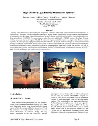
Figure 1: HELIOS IV during systems testing Figure 2: Sunrise launch of HASP
1. Introduction
1.1 The HELIOS Program
Solar observation is done primarily via two methods--
ground observatories and satellites--both of which have
major drawbacks. Ground observatories are limited by the
amount of interference caused by the atmosphere. While
this interference is usually minimal at night for star and
planet observation, it increases during the day,
making observation of the Sun challenging. Satellite
telescopes overcome this issue, but cost far more to create,
put into orbit, and maintain. The HELIOS program was
created to solve both of these major issues by proving the
viability of solar observation via a high altitude balloon
platform. This method allows the telescope to be above
99.5% of Earth’s atmosphere, and it is far less expensive
than satellite telescopes. Starting in 2012 with the first
HELIOS mission, the team set out with a goal to capture
images of the Sun in the Hydrogen Alpha (H-ɑ) and
Calcium K (CaK) wavelengths. These wavelengths allow
the imaging camera to penetrate through the upper layers
2. 2008 COSGC Space Research Symposium Page 2
of the Sun to view solar features such as sunspots and solar
flares in H-ɑ, and see magnetic activity on the Sun in the
CaK wavelengths. This mission was not as successful as
they had hoped,so the next two missions, HELIOS II and
III, were dedicated to developing a strong Attitude
Determination and Control System (ADCS) algorithm so
that the payload was betterable to track the Sun throughout
its flight. These missions also switched to only imaging in
the H-ɑ wavelength to simplify the necessary optics
equipment. Last year, HELIOS IV’s mission was to prove
the upgraded tracking capabilities of the payload, and
demonstrate that HELIOS would have enough accuracy to
capture images of the Sun if an optics systemwas added.
HELIOS IV did not fly such an optics systembecause their
focus was to prove the tracking ability of the payload. This
is HELIOS V’s mission: to implement the new optics
system, including a telescope, several filters, and a
science camera, so that the payload can capture images of
the Sun in the H-ɑ wavelength. The new systemis built off
the success ofHELIOS IV¹; therefore, the HELIOS V team
is changing very little about the payload. The goal is to
accommodate the new optics system and add only small
other changes that will improve the performance of the
payload to produce the best quality images.
1.2 Mission Objectives
HELIOS V will use the HELIOS IV tracking systemto
track and take pictures of the Sun in the H-ɑ wavelength.
Primary Objectives:
Take advantage of the successful HELIOS IV
systemto gather science data
Capture images of the Sun in the H-ɑ wavelength
Secondary Objectives:
Demonstrate that the upper housing can serve as
a bus for other science missions
1.3 The HASP Program
HELIOS V is a large payload project that will fly on the
2016 High Altitude Student Platform (HASP). It will be the
ninth payload that the Colorado Space Grant Consortium
(COSGC) at the University of Colorado at Boulder has
flown with the HASP team. This program is supported by
the NASA Balloon Program Office and the Louisiana
Space Grant Consortium as a vehicle that student projects
can travel on to run experiments in the high atmosphere.
The platform flies in late August out of Fort Sumner, New
Mexico. It will travel to an altitude of about 36 km where
it will stay at float for anywhere between 5 to 24 hours
depending on weather conditions.
2. Concept of Operations
Figure 3 shows the concept of operations for HELIOS
V. This concept of operations is based on a 7 am launch
time on August 29th, which is the current projected launch
date. The HASP platform will ascend to 36 km in the first
two hours of flight. During this time the HELIOS V
payload will be powered on, tracking, and capturing
images. The optimal tracking time will be during float,
which is from 2 to about 12.5 hours into flight. At float the
payload is the most stable, meaning that HELIOS can be
centered on the Sun for longer periods of time than what is
usually possible during ascent. At about 12.5 hours into
flight is sunset. At this time, the ADCS system and the
science camera shall be powered off. Additionally, the
payload will be locked at a predetermined azimuth and
elevation. The Star Tracker will then be powered
throughout the night until sunrise. Sunrise occurs at about
23.5 hours after launch, at which point the Star Tracker
shall be powered off. If possible, the ADCS and science
camera systems will be powered on again for additional
Sun tracking, though this may not be possible if the system
is too cold in the morning. At this point, the platform may
be cut down at any time. Prior to cut down, all payloads
onboard the platform will be powered off for descent,
which lasts about one to two hours. The payload will be
recovered sometime after. This diagram details the optimal
mission, so all of the times indicated may be different than
in the actual flight because HASP flights vary in time.
Figure 3: HELIOS V Concept of Operations
3. System Details
HELIOS V will take advantage of the tracking system
developed for HELIOS IV in order to track the Sun during
its flight on HASP. HELIOS is equipped with an elevation
3. 2008 COSGC Space Research Symposium Page 3
and azimuth motor, which it uses to orient the upper
housing to face the Sun. The Sun-tracking system on
HELIOS V will use photodiodes to find the Sun and guide
HELIOS to center the Sun in front of the payload. Once
there, the ADCS camera will place the Sun within the field
of view (FOV) of the science camera.
In order to take images of the Sun in the H-ɑ
wavelength, HELIOS V will fly a telescope in addition to
a camera. The telescope will be equipped with several
filters in order to isolate the desired wavelength. Once the
ADCS camera has centered the Sun into the FOV of the
camera, the camera will take pictures of the Sun, ideally
capturing images of sunspots which can be used for
scientific purposes.
The command and data handling (CDH) subsystemwill
use two Raspberry Pi 2’s to receive, store, and output data
to the other systems and the HASP platform. To power the
systems, the electrical power system (EPS) will receive
power from HASP, trim the voltage to the appropriate
number, and delegate that power to the other systems.
3.1. Optics
The HELIOS V optics system is composed of two
camera systems with separate objectives. The ADCS
camera systemis used in tracking the Sun for the ADCS
algorithm while the science camera systemis designed to
capture images of the Sun in the H-ɑ wavelength. These
two camera systems will be mounted parallel to each other
in the upper housing of the payload.
3.1.1 ADCS Camera
The ADCS camera is a See3CAM_10CUG, shown in
Figure 4, with a neutral density filter over the lens. The
filter removes excess light from coming into the camera,
which helps the camera clearly define the disk of the Sun
and also lowers the temperature of the camera. This
camera has a very large field of view of 22.9° x 17.2° so
that it has a higher chance ofcapturing the Sun in an image.
Once the ADCS camera sees the Sun in its FOV, the
tracking algorithm (further details in section 3.3) aims the
payload at the Sun.
Figure 4: ADCS camera
3.1.2 Science Optics System
The science optics systemis comprised of three major
pieces: the telescope, filters, and science camera. This
system is building off of the optics design originally
created for HELIOS III. The telescope is an Orion
telescope selected because of its Maksutov-Cassegrain set
up.A Maksutov-Cassegrain telescope doubles the effective
focal length of the camera by reflecting the light back onto
a mirror on the main lens before going through the
eyepiece. This allows the system to be shorter in length
while producing a more focused image. The system
includes several filters, the first of which goes over the
camera lens. This is the neutral density filter, which, like
on the ADCS camera, filters out excess light and keeps the
system cool. The next several filters are mounted in the
barrel behind the telescope. The first of these is the H-ɑ
filter, which only allows wavelengths within 3 nm of
656.28 nm (the wavelength of H-ɑ) through.After this is a
.44x focal reducer, which helps to furthershorten the optics
systemso that it fits on the HELIOS structure. The focal
reducer is a change from the previous HELIOS III design
which had a .5x focal reducer. The change increases the
FOV from .779° x .623° to .885° x .708°, which gives the
science camera a better chance to capture an image of the
Sun.
4. 2008 COSGC Space Research Symposium Page 4
Figure 5: Filter set up for the ADCS (top) and science
(bottom) cameras
3.1.3 Star Tracker
The HELIOS V system will be hosting a Star Tracker
from COSGC’s PolarCube team. The Star Tracker will
demonstrate that the HELIOS payload can be used as a bus
for other science missions, fulfilling the secondary mission
objective, as well as giving the HELIOS payload a
nighttime mission. Due to the excess space in the upper
housing behind the ADCS camera, the HELIOS team
wants to utilize that space for other science missions. Last
year, HELIOS IV’s flight lasted nearly 26 hours,meaning
that for a large time period, the HELIOS payload was
dormant during the night. The star tracker allows the
HELIOS payload to use all of its flight time.
The Star Tracker is primarily being handled by the
PolarCube team, meaning the HELIOS team will only be
supplying it with 5 volts of power as well as a USB
connection to the upper Raspberry Pi 2 for saving images.
3.1.4 Expected Images
The ultimate goal of the payload is to capture images of
the Sun in the H-ɑ wavelength. Figure 6 shows the
expected image that shows how large the sun will be with
the radius of the Sun being 0.5°.
Figure 6: Expected science camera image
For the expected images in H-ɑ, the pictures will appear
in grayscale. The two images below are test images from
HELIOS III (Figure 7) and HELIOS V before the .44x
reducer was added (Figure 8). Dark sunspots are marked in
red. Other markings on the image are caused by dust
particles on the lens. To reduce interference from dust
particles, the telescope and camera will be cleaned
thoroughly before launch.
Figure 7: Sunspots in test images from HELIOS III
5. 2008 COSGC Space Research Symposium Page 5
Figure 8: Sunspots in test images from HELIOS V
3.2. Structures
The majority of the structure from HELIOS IV will be
reused in the HELIOS V mission. The structure proved
sufficient for sustained tracking. The upper housing,
however, is to be elongated from 16.51 cm to 22.86 cm to
accommodate for the larger telescope system.
The HELIOS structure consists of three separate
sections: lower housing, intermediate housing, and upper
housing.The lower housing begins with an aluminum 6061
baseplate, cut to fit the specifications from HASP. This
rigid board serves as a steady base for the payload as well
as an efficient heat sink. The electronics board and
Raspberry Pi, both ofwhich are secured onto the baseplate,
heat up during flight. This heat sink provides a means for
the energy to be dissipated,protecting the equipment. Also
in the lower housing is the azimuth motor. The azimuth
motor precisely rotates the upper and intermediate housing
with a 4:1 gear ratio.
HELIOS V’s intermediate housing holds the key
structure together. Able to freely rotate, the intermediate
housing joins the lower housing to the upper housing. This
housing turns with the upper housing in the azimut h
direction, as well as providing a base for the upper housing
to turn in the elevation direction. The wires running from
the lower housing to the upper housing are threaded
through the intermediate housing.
The core section of the structure is the upper housing,
home to the camera systems. The ADCS tracking system
includes the two photodiode housings and the ADCS
camera. These will be mounted on the outside of the upper
housing, and inside the upper housing, respectively. The
ADCS camera and the telescope systemwill be mounted in
parallel with each other, so they are both capturing images
of the same point. The telescope will secured on the right
of the upper housing,leaving space for the existing ADCS
camera on the left. The Raspberry Pi in the upper housing
will be secured to the floor of the upper housing, and
PolarCube’s Star Tracker will be integrated to the back of
the payload.
HELIOS IV experienced an issue with a counterweight
falling prior to flight. This caused a large source of error
in the mission because it limited tracking capabilities. Due
to this, the HELIOS V team will thoroughly address this
issue by redesigning the counterweight system.
Figure 9: HELIOS V structure
1. Base Plate 6. ADCS Camera
2. Lower Housing 7. Diode Housing
3. Intermediate Housing 8. Science Camera
4. Upper Housing 9. Star Tracker
5. Science Telescope
3.3. Altitude Determination and Control Systems
The Sun-tracking system on HELIOS IV had two
components: a coarse-tracking systemand a fine-tracking
system. The coarse tracking used photodiodes to find the
Sun and guide HELIOS to center the Sun in front of the
payload. The fine tracking was accomplished using the
ADCS camera, which took images of the Sun, analyzed
them, and indicated how the payload should move so that
the disk of the Sun is centered in the pictures taken by the
ADCS camera. This subsystemplays an especially critical
role, since the science camera has a small field of view.
HELIOS uses four photodiodes to find and center the
Sun within the FOV of the ADCS camera. The diodes have
a 30° FOV through their encasement and are at a 90° angle
relative to each other, meaning a perfectly centered Sun
will strike each diode at 45°. When the Sun is not centered,
the sunlight strikes the diodes at different angles, leading
to a difference in intensity. This difference in intensity is
6. 2008 COSGC Space Research Symposium Page 6
quickly calculated and the payload moves in a direction
towards the Sun accordingly. Once the photodiodes have
successfully brought the Sun within the ADCS camera’s
field of view, the ADCS camera takes over and begins fine
tracking.
Figure 10: Interior of Photodiode
Figure 11: Front view of upper housing
The ADCS flight loop constantly checks if the Sun is in
the field of view of the ADCS camera. If it is, the program
defines the disk of the Sun and its distance to the center of
the image as seen in Figure 12. Based on the location of
the Sun, the loop determines and executes the appropriate
steps with the motors to move the Sun closer to the center.
Figure 12: Sun tracking algorithm centering the Sun in the
field of view
Improvements on the most recent iteration of HELIOS
will include smoothing the tracking motion of the camera,
and ensuring the ability of the payload to focus on the Sun
for an extended period of time. After analysis of the
counter-weight failure of the previous mission, a physical
reset switch will be implemented to avoid the possibility of
a similar failure in the future. This mechanism will give
the payload the ability to reset its internal counter in case
of another mechanical problem, ensuring that the mission
will still be successful.
3.4. Command and Data Handling
The CDH systemaboard HELIOS V will be responsible
for communications with the HASP platform, collecting
and managing data from the other subsystems. The CDH
system shall utilize two Raspberry Pi 2 microcontrollers
and flight code written in Python. Previous HELIOS
missions flew a single Raspberry Pi 2 in the lower housing.
The second Raspberry Pi 2 is a new addition, which will be
placed in the upper housing to help with the increased
processing necessitated by the Star Tracker and science
camera. For HELIOS V, the code efficiency will be
optimized and the communication will be more efficient
and robust.Figure 13 shows how all the components of the
systeminteract with regards to power and data flow.
Figure 13: Functional Block Diagram
3.4.1 Raspberry Pi 2’s
The Raspberry Pi 2 in the lower housing is the primary
component in the CDH subsystem. It is responsible for
controlling communications with the HASP platform,
capturing and storing ADCS images, supporting the ADCS
subsystem, monitoring the photodiode arrays, controlling
the motor drivers, and tracking the Sun. For serial
communication with the HASP platform, it shall be
connected using a RS232 to USB serial converter. For
serial communication to the ADCS subsystem, the ADCS
camera shall be connected to the Raspberry Pi with a USB
7. 2008 COSGC Space Research Symposium Page 7
2.0. In order to accomplish this wide variety of goals, the
Raspberry Pi shall run flight software that is separated into
distinct threads, which run concurrently on the processor.
The Raspberry Pi in the upperhousing shall be responsible
for saving images directly from the science camera and the
Star Tracker. This image data will be saved to an internal
SD card. The purpose for using a secondary Raspberry Pi
2 in the upper housing is to minimize changes to the
software that was successfully implemented on the lower
Raspberry Pi 2 for previous HELIOS missions, as well as
avoid burdening the lower Raspberry Pi with additional
tasks.
Each Raspberry Pi 2 runs off Inter-integrated Circuit
(I²C). With only two wires, a clock line (SCL) and data
line (SDA), all of the Pi’s sensors can communicate to each
other with ease. Previous HELIOS missions used I²C, and
HELIOS V will do the same to reduce changes to the EPS
board. I²C is sufficient for the mission, for it allows a few
bytes of data to be sent at a time, adequate for commands
and simple health checks.If there are any issues concerning
the performance of the Raspberry Pi in the upper housing,
it shall be rebooted manually via the Raspberry Pi in the
lower housing.
The two Raspberry Pi’s will communicate with each
other using universal asynchronous receiver/transmitter
(UART). I²C communication between two Pi’s requires
one to be a “slave” device to a “master”. This could prove
problematic because both Pi’s are usually “masters”,which
is where UART comes in. UART will allow for more
complex data and commands to be sent between the two
Pi’s. Detailed health checks need to be written so that the
health of the upper Raspberry Pi and Star Tracker can be
monitored effectively. Most importantly, however, is that
UART will allow for the two Pi’s to read from the same
real time clock (RTC), which is necessary forsynchronized
timestamp of data and pictures. Both Pi’s have their UART
pins available, therefore connection shall be simple.
3.4.2 Uplink Thread
The uplink thread is responsible for awaiting two-byte
serial commands uplinked by the ground station. It is idle
until it detects data in the serial buffers. When it detects
data in the serial buffers, relevant data will be passed to the
appropriate threads,and a confirmation will be downlinked
to the ground. If there are any issues with the uplinked
command, it shall downlink an error to the ground.
3.4.3 Downlink Thread
The downlink thread will process and downlink data
from the other threads to the ground. The payload shall
allow serial downlink functioning at 4800 baud. It is idle
until it is passed a data package from another thread with
the correct identifier, record type, and data. Once a
complete and correct data package has been passed,it will
format the information in the package into the downlink
format. The downlink thread will identify any data loss or
corruption, as well as allow for easy sorting of data. The
packetized data will be downlinked at about 350 bit/s.
3.4.4 Sun Tracking Thread
The Sun tracking thread is the most expansive and
resource intensive thread.It shall analyze readings from the
photodiodes and analyze all pictures taken on the ADCS
camera in order to provide direction for both the azimuth
and elevation motors.
3.4.5 Sense Thread
The sense thread shall sample data from each sensor,
including health checks on the upper Raspberry Pi and Star
Tracker. This will allow the HELIOS team to monitor the
status of the payload during flight. The data will be
packaged and downlinked to the HASP platform. This
thread will also handle any commands necessary to operate
the Raspberry Pi in the upperhousing.Additionally, it will
save data to the SD cards.
3.5. Electrical Systems
HELIOS V will receive 30 volts DC from the HASP
platform to be dispersed throughout the payload. Two DC-
DC buck converters will be used to step down the voltage
to 12 volts and 5 volts.A trimming resistorwill trim the 12
volts to the 10.8 volts necessary to operate the motor
drivers while the 5 volt line is sent to the upperhousing and
Raspberry Pi. All components of the system will be
equipped with individual power protection systems to
eliminate the need for external monitoring of the power
systems.
The power budget in Figure 14 includes all major
components ofthe systemat maximum voltage and current
draw. The maximum power of the systemis 49.82 watts.
Therefore, the maximum current draw from the platform is
1.66 amps, which is well under HASP’s limit of 2.5 amps,
so this will not be a risk. As many of the components flying
on HELIOS V were flown on HELIOS III and HELIOS IV,
no major revisions to the printed circuit board will be
necessary.Instead of designing, implementing, and testing
a newcircuit board, HELIOS V will use the board designed
for HELIOS III, with a few minor changes to accommodate
the new systems.
The new components on HELIOS V are the Raspberry
Pi in the upper housing, the science camera, and the Star
Tracker. The Raspberry Pi 2 will be connected to the main
PCB board for power by repurposing the power line for the
GoPro flown on HELIOS IV. The science camera and the
8. 2008 COSGC Space Research Symposium Page 8
Star Tracker will each receive 5 volts from the Raspberry
Pi 2 in the upper housing via USB.
Figure 14: HELIOS V power budget
4. Conclusions
The basis of the HELIOS program is to provide an
alternative to ground based solar observation and satellite
telescopes. After four previous missions, the primary
tracking system has been proven successful. Now,
HELIOS V has the tools necessary to achieve the
program’s objectives, ultimately capturing images in the
H-ɑ wavelength.
Future mission objectives could include collaborating
with researchers in the field of solar observation,
photographing the Sun in different wavelengths, and
improving the nighttime functionality of HELIOS.
5. References
[1] Arthur, P., Benson, C., Cutter, R., Gordivas, F.,
Hanslik, K., and Richards, D., “Hydrogen-Alpha
Exploration with Light Intensity Observation Systems IV,”
University of Colorado at Boulder, Boulder, Colorado,
2015 (Unpublished).