SlideShare a Scribd company logo
1 of 138
Download to read offline
350209 N/C 25 February 2014
TECHNICAL MANUAL
OPERATION AND MAINTENANCE
NITROGEN GENERATING UNIT
(BUNDLE BOX)
MODEL NUMBER: 2000 HPNGUBB
PART NUMBER: 799020-001
Pacific Consolidated Industries, LLC
12201 Magnolia Avenue
Riverside, California 92503-4820
Tel: 951-479-0860
Fax: 951-479-0861
http://www.pcigases.com
Copyright  2014 by Pacific Consolidated Industries, LLC (PCI). This document contains confidential technical data,
including trade secrets, proprietary to PCI. Disclosure of this data is expressly conditioned upon your assent that its
use is limited to use within your company only (and does not include manufacture or processing uses). No part of this
document may be used or reproduced in any form or by any means or stored in a database or retrieval system without
written permission of PCI. Copying or directly reproducing any part of this manual for any purpose other than the
original owner’s personal use is a violation of the United States Copyright laws. For more information and assistance
in obtaining additional copies of this manual, contact Pacific Consolidated Industries, LLC, 12201 Magnolia Avenue,
Riverside, California 92503-4820.
This manual is presented as-is, without warranty of any kind, either expressed or implied, respecting its contents,
including, but not limited to implied warranties for the manual’s quality. PCI is not liable to the purchaser or any other
person or entity with respect to any liability, loss, or damage caused or alleged to have been caused directly or
indirectly by this manual. Pacific Consolidated Industries assumes no responsibility for the accuracy, completeness or
usefulness of this manual, or from any problems or conditions which may arise from the use of the information
contained herein or omissions from this manual. Pacific Consolidated Industries reserves the right to change and
update the information and specifications contained within this manual at any time without notice.
REVISION DATE DESCRIPTION DCN
N/C 25 Feb 2014 Initial Release 3721
TABLE OF CONTENTS
PARAGRAPH PAGE
350209 i
Nitrogen Generating Unit
2000 HPNGUBB
Foreword. . . . . . . . . . . . . . . . . . . . . . . . . . . . . . . . . . . . . . . . . . . . . . . . . . . . . . . . . . . . . . . . . . . . . . . . . . . . vii
Safety Summary . . . . . . . . . . . . . . . . . . . . . . . . . . . . . . . . . . . . . . . . . . . . . . . . . . . . . . . . . . . . . . . . . . . . . . ix
1 INTRODUCTION
1.1 Scope . . . . . . . . . . . . . . . . . . . . . . . . . . . . . . . . . . . . . . . . . . . . . . . . . . . . . . . . . . . . . . . . . . . . . . . . . . . . . . 1-1
1.2 Operation . . . . . . . . . . . . . . . . . . . . . . . . . . . . . . . . . . . . . . . . . . . . . . . . . . . . . . . . . . . . . . . . . . . . . . . . . . . 1-1
1.3 Equipment Description . . . . . . . . . . . . . . . . . . . . . . . . . . . . . . . . . . . . . . . . . . . . . . . . . . . . . . . . . . . . . . . . . 1-1
1.3.1 Major Components. . . . . . . . . . . . . . . . . . . . . . . . . . . . . . . . . . . . . . . . . . . . . . . . . . . . . . . . . . . . . . . . . . . . 1-1
1.4 Associated Technical Documentation . . . . . . . . . . . . . . . . . . . . . . . . . . . . . . . . . . . . . . . . . . . . . . . . . . . . . 1-1
1.5 Leading Particulars . . . . . . . . . . . . . . . . . . . . . . . . . . . . . . . . . . . . . . . . . . . . . . . . . . . . . . . . . . . . . . . . . . . 1-3
1.6 Bundle Box Access Doors . . . . . . . . . . . . . . . . . . . . . . . . . . . . . . . . . . . . . . . . . . . . . . . . . . . . . . . . . . . . . . 1-4
1.7 Acronyms and Abbreviations . . . . . . . . . . . . . . . . . . . . . . . . . . . . . . . . . . . . . . . . . . . . . . . . . . . . . . . . . . . . 1-5
2 PREPARATION FOR USE, SHIPMENT AND STORAGE
2.1 Preparation for Use . . . . . . . . . . . . . . . . . . . . . . . . . . . . . . . . . . . . . . . . . . . . . . . . . . . . . . . . . . . . . . . . . . . 2-1
2.1.1 Site Conditions . . . . . . . . . . . . . . . . . . . . . . . . . . . . . . . . . . . . . . . . . . . . . . . . . . . . . . . . . . . . . . . . . . . . . . . 2-1
2.1.2 Installation . . . . . . . . . . . . . . . . . . . . . . . . . . . . . . . . . . . . . . . . . . . . . . . . . . . . . . . . . . . . . . . . . . . . . . . . . . 2-1
2.1.3 External Equipment Hookup . . . . . . . . . . . . . . . . . . . . . . . . . . . . . . . . . . . . . . . . . . . . . . . . . . . . . . . . . . . . 2-3
2.1.3.1 Electrical Power Hookup . . . . . . . . . . . . . . . . . . . . . . . . . . . . . . . . . . . . . . . . . . . . . . . . . . . . . . . . . . . . . . . 2-3
2.1.4 Container Lighting . . . . . . . . . . . . . . . . . . . . . . . . . . . . . . . . . . . . . . . . . . . . . . . . . . . . . . . . . . . . . . . . . . . . 2-4
2.2 Preparation for Shipment or Storage . . . . . . . . . . . . . . . . . . . . . . . . . . . . . . . . . . . . . . . . . . . . . . . . . . . . . . 2-5
2.2.1 Preparation For Shipment . . . . . . . . . . . . . . . . . . . . . . . . . . . . . . . . . . . . . . . . . . . . . . . . . . . . . . . . . . . . . . 2-5
2.2.2 Preparation For Storage. . . . . . . . . . . . . . . . . . . . . . . . . . . . . . . . . . . . . . . . . . . . . . . . . . . . . . . . . . . . . . . . 2-8
2.2.2.1 Storage Facility . . . . . . . . . . . . . . . . . . . . . . . . . . . . . . . . . . . . . . . . . . . . . . . . . . . . . . . . . . . . . . . . . . . . . . 2-9
2.2.2.2 Outdoor Storage. . . . . . . . . . . . . . . . . . . . . . . . . . . . . . . . . . . . . . . . . . . . . . . . . . . . . . . . . . . . . . . . . . . . . . 2-9
3 OPERATION
3.1 Controls and Indicators . . . . . . . . . . . . . . . . . . . . . . . . . . . . . . . . . . . . . . . . . . . . . . . . . . . . . . . . . . . . . . . . 3-1
3.2 Pre-Operation Instructions . . . . . . . . . . . . . . . . . . . . . . . . . . . . . . . . . . . . . . . . . . . . . . . . . . . . . . . . . . . . . . 3-2
3.3 Operation . . . . . . . . . . . . . . . . . . . . . . . . . . . . . . . . . . . . . . . . . . . . . . . . . . . . . . . . . . . . . . . . . . . . . . . . . . . 3-6
3.3.1 Operation Adjustments. . . . . . . . . . . . . . . . . . . . . . . . . . . . . . . . . . . . . . . . . . . . . . . . . . . . . . . . . . . . . . . . 3-10
3.4 Data Logging . . . . . . . . . . . . . . . . . . . . . . . . . . . . . . . . . . . . . . . . . . . . . . . . . . . . . . . . . . . . . . . . . . . . . . . 3-12
3.4.1 Data Logging Software Installation . . . . . . . . . . . . . . . . . . . . . . . . . . . . . . . . . . . . . . . . . . . . . . . . . . . . . . 3-13
3.4.1.1 Windows 98/2000/XP® & Excel® 2003 . . . . . . . . . . . . . . . . . . . . . . . . . . . . . . . . . . . . . . . . . . . . . . . . . . . 3-13
3.4.1.2 Windows 7® & Excel® 2010 . . . . . . . . . . . . . . . . . . . . . . . . . . . . . . . . . . . . . . . . . . . . . . . . . . . . . . . . . . . 3-14
3.4.2 Log The Data . . . . . . . . . . . . . . . . . . . . . . . . . . . . . . . . . . . . . . . . . . . . . . . . . . . . . . . . . . . . . . . . . . . . . . . 3-16
3.5 Performance. . . . . . . . . . . . . . . . . . . . . . . . . . . . . . . . . . . . . . . . . . . . . . . . . . . . . . . . . . . . . . . . . . . . . . . . 3-17
3.5.1 Membrane Performance. . . . . . . . . . . . . . . . . . . . . . . . . . . . . . . . . . . . . . . . . . . . . . . . . . . . . . . . . . . . . . . 3-17
3.5.2 Flow vs Purity. . . . . . . . . . . . . . . . . . . . . . . . . . . . . . . . . . . . . . . . . . . . . . . . . . . . . . . . . . . . . . . . . . . . . . . 3-18
3.5.3 Performance Troubleshooting . . . . . . . . . . . . . . . . . . . . . . . . . . . . . . . . . . . . . . . . . . . . . . . . . . . . . . . . . . 3-19
3.6 Shut-Down . . . . . . . . . . . . . . . . . . . . . . . . . . . . . . . . . . . . . . . . . . . . . . . . . . . . . . . . . . . . . . . . . . . . . . . . . 3-20
3.6.1 Emergency Stop. . . . . . . . . . . . . . . . . . . . . . . . . . . . . . . . . . . . . . . . . . . . . . . . . . . . . . . . . . . . . . . . . . . . . 3-21
4 THEORY OF OPERATION
4.1 Nitrogen Production . . . . . . . . . . . . . . . . . . . . . . . . . . . . . . . . . . . . . . . . . . . . . . . . . . . . . . . . . . . . . . . . . . . 4-1
4.2 Operation Components . . . . . . . . . . . . . . . . . . . . . . . . . . . . . . . . . . . . . . . . . . . . . . . . . . . . . . . . . . . . . . . . 4-2
4.2.1 Feed Air and Discharge Operation Components . . . . . . . . . . . . . . . . . . . . . . . . . . . . . . . . . . . . . . . . . . . . . 4-3
PARAGRAPH PAGE
ii 350209
Nitrogen Generating Unit
2000 HPNGUBB
4.2.2 Filter Tower Components . . . . . . . . . . . . . . . . . . . . . . . . . . . . . . . . . . . . . . . . . . . . . . . . . . . . . . . . . . . . . . .4-4
4.2.3 Membrane Assembly Components . . . . . . . . . . . . . . . . . . . . . . . . . . . . . . . . . . . . . . . . . . . . . . . . . . . . . . . .4-6
4.2.4 Other Operation Components . . . . . . . . . . . . . . . . . . . . . . . . . . . . . . . . . . . . . . . . . . . . . . . . . . . . . . . . . . . .4-8
4.2.5 Electrical Enclosure Components . . . . . . . . . . . . . . . . . . . . . . . . . . . . . . . . . . . . . . . . . . . . . . . . . . . . . . . . .4-9
5 CALIBRATION
5.1 Calibration and Verification . . . . . . . . . . . . . . . . . . . . . . . . . . . . . . . . . . . . . . . . . . . . . . . . . . . . . . . . . . . . . .5-1
5.1.1 Calibration and Verification Intervals . . . . . . . . . . . . . . . . . . . . . . . . . . . . . . . . . . . . . . . . . . . . . . . . . . . . . . .5-1
5.1.2 Calibration Definitions . . . . . . . . . . . . . . . . . . . . . . . . . . . . . . . . . . . . . . . . . . . . . . . . . . . . . . . . . . . . . . . . . .5-1
5.1.3 Calibration Data SHeets and Records. . . . . . . . . . . . . . . . . . . . . . . . . . . . . . . . . . . . . . . . . . . . . . . . . . . . . .5-2
5.1.4 Calibration Device Information. . . . . . . . . . . . . . . . . . . . . . . . . . . . . . . . . . . . . . . . . . . . . . . . . . . . . . . . . . . .5-3
5.1.5 Calibration Environmental Conditions . . . . . . . . . . . . . . . . . . . . . . . . . . . . . . . . . . . . . . . . . . . . . . . . . . . . . .5-3
5.1.6 Calibration Measurement Equipment Requirements. . . . . . . . . . . . . . . . . . . . . . . . . . . . . . . . . . . . . . . . . . .5-3
5.1.7 Calibration Support Equipment . . . . . . . . . . . . . . . . . . . . . . . . . . . . . . . . . . . . . . . . . . . . . . . . . . . . . . . . . . .5-4
5.2 Resistance Temperature Detector (RTD) Verification . . . . . . . . . . . . . . . . . . . . . . . . . . . . . . . . . . . . . . . . . .5-4
5.2.1 RTD-7 Amplifier Calibration. . . . . . . . . . . . . . . . . . . . . . . . . . . . . . . . . . . . . . . . . . . . . . . . . . . . . . . . . . . . . .5-6
5.3 Flowmeter Verification . . . . . . . . . . . . . . . . . . . . . . . . . . . . . . . . . . . . . . . . . . . . . . . . . . . . . . . . . . . . . . . . . .5-7
5.3.1 Flowmeter (MFT-1) . . . . . . . . . . . . . . . . . . . . . . . . . . . . . . . . . . . . . . . . . . . . . . . . . . . . . . . . . . . . . . . . . . . .5-7
5.3.1.1 Flowmeter (MFT-1) Instllation . . . . . . . . . . . . . . . . . . . . . . . . . . . . . . . . . . . . . . . . . . . . . . . . . . . . . . . . . . .5-10
5.4 O2 Sensor Calibration (NA-1) . . . . . . . . . . . . . . . . . . . . . . . . . . . . . . . . . . . . . . . . . . . . . . . . . . . . . . . . . . .5-11
6 MAINTENANCE
6.1 Maintenance Responsibility. . . . . . . . . . . . . . . . . . . . . . . . . . . . . . . . . . . . . . . . . . . . . . . . . . . . . . . . . . . . . .6-1
6.1.1 Maintenance Data Sheets and Records . . . . . . . . . . . . . . . . . . . . . . . . . . . . . . . . . . . . . . . . . . . . . . . . . . . .6-1
6.2 Tools and Test Equipment. . . . . . . . . . . . . . . . . . . . . . . . . . . . . . . . . . . . . . . . . . . . . . . . . . . . . . . . . . . . . . .6-1
6.2.1 Cleanliness . . . . . . . . . . . . . . . . . . . . . . . . . . . . . . . . . . . . . . . . . . . . . . . . . . . . . . . . . . . . . . . . . . . . . . . . . .6-2
6.3 Maintenance and Inspection Requirements . . . . . . . . . . . . . . . . . . . . . . . . . . . . . . . . . . . . . . . . . . . . . . . . .6-2
6.3.1 Replacement Intervals. . . . . . . . . . . . . . . . . . . . . . . . . . . . . . . . . . . . . . . . . . . . . . . . . . . . . . . . . . . . . . . . . .6-2
6.4 Touch-Up Paint . . . . . . . . . . . . . . . . . . . . . . . . . . . . . . . . . . . . . . . . . . . . . . . . . . . . . . . . . . . . . . . . . . . . . . .6-3
6.5 General Overhaul Instructions. . . . . . . . . . . . . . . . . . . . . . . . . . . . . . . . . . . . . . . . . . . . . . . . . . . . . . . . . . . .6-3
6.6 Seal Replacement . . . . . . . . . . . . . . . . . . . . . . . . . . . . . . . . . . . . . . . . . . . . . . . . . . . . . . . . . . . . . . . . . . . . .6-4
6.7 CPU and Touch Screen Battery Replacement . . . . . . . . . . . . . . . . . . . . . . . . . . . . . . . . . . . . . . . . . . . . . . .6-5
6.7.1 CPU Battery Replacement. . . . . . . . . . . . . . . . . . . . . . . . . . . . . . . . . . . . . . . . . . . . . . . . . . . . . . . . . . . . . . .6-6
6.7.2 Touch Screen Battery Replacement . . . . . . . . . . . . . . . . . . . . . . . . . . . . . . . . . . . . . . . . . . . . . . . . . . . . . . .6-6
6.8 Post Maintenance, Service and Repair Examination. . . . . . . . . . . . . . . . . . . . . . . . . . . . . . . . . . . . . . . . . . .6-7
Appendix A Flow Diagram - - - - - - - - - - - - - - - - - - - - - - - - - - - - - - - - - - - - - - - - - A-1
Appendix B Membrane Performance Tables - - - - - - - - - - - - - - - - - - - - - - - - - - - - - - - - - B-1
Appendix C Process and Insrtumentaion Diagram with Bill of Materials - - - - - - - - - - - - - - - - - - - C-1
Appendix D Electrical Schematic with Bill of Materials - - - - - - - - - - - - - - - - - - - - - - - - - - - - D-1
Appendix E Control Screens - - - - - - - - - - - - - - - - - - - - - - - - - - - - - - - - - - - - - - - - E-1
Appendix F Spare Parts - - - - - - - - - - - - - - - - - - - - - - - - - - - - - - - - - - - - - - - - - - F-1
LIST OF ILLUSTRATIONS
FIGURE PAGE
350209 iii
Nitrogen Generating Unit
2000 HPNGUBB
1-1 Major Components - - - - - - - - - - - - - - - - - - - - - - - - - - - - - - - - - - - - - - - - - - 1-2
1-2 Access Doors - - - - - - - - - - - - - - - - - - - - - - - - - - - - - - - - - - - - - - - - - - - - - 1-4
2-1 Bundle Box Ports - - - - - - - - - - - - - - - - - - - - - - - - - - - - - - - - - - - - - - - - - - - 2-2
2-2 Electrical Enclosure Back Panel (Transformer (XFR-1)- - - - - - - - - - - - - - - - - - - - - - - - - 2-4
2-3 Bundle Box Operator Control Panel - - - - - - - - - - - - - - - - - - - - - - - - - - - - - - - - - - 2-5
2-4 Discharge Plumbing- - - - - - - - - - - - - - - - - - - - - - - - - - - - - - - - - - - - - - - - - - 2-6
2-5 Separator and Filter Drains - - - - - - - - - - - - - - - - - - - - - - - - - - - - - - - - - - - - - - 2-7
2-6 Feed Air Plumbing - - - - - - - - - - - - - - - - - - - - - - - - - - - - - - - - - - - - - - - - - - 2-8
2-7 Outdoor Storage Preparation - - - - - - - - - - - - - - - - - - - - - - - - - - - - - - - - - - - - - 2-10
3-1 Operator Panel - - - - - - - - - - - - - - - - - - - - - - - - - - - - - - - - - - - - - - - - - - - - 3-1
3-2 Feed Valves - - - - - - - - - - - - - - - - - - - - - - - - - - - - - - - - - - - - - - - - - - - - - 3-3
3-3 Discharge Valves - - - - - - - - - - - - - - - - - - - - - - - - - - - - - - - - - - - - - - - - - - - 3-4
3-4 Filter Drain Valves - - - - - - - - - - - - - - - - - - - - - - - - - - - - - - - - - - - - - - - - - - 3-4
3-5 Membrane Inlet Valves - - - - - - - - - - - - - - - - - - - - - - - - - - - - - - - - - - - - - - - - 3-5
3-6 Operator Process Controls and Valves - - - - - - - - - - - - - - - - - - - - - - - - - - - - - - - - 3-6
3-7 NGU Screen - - - - - - - - - - - - - - - - - - - - - - - - - - - - - - - - - - - - - - - - - - - - - 3-7
3-8 Differential Gauges (DPG-1 - 4) - - - - - - - - - - - - - - - - - - - - - - - - - - - - - - - - - - - - 3-9
3-9 Setup Screen - - - - - - - - - - - - - - - - - - - - - - - - - - - - - - - - - - - - - - - - - - - - - 3-10
3-10 Ethernet Port on the Operator Panel- - - - - - - - - - - - - - - - - - - - - - - - - - - - - - - - - - 3-17
3-11 Feed Air Valves - - - - - - - - - - - - - - - - - - - - - - - - - - - - - - - - - - - - - - - - - - - - 3-20
3-12 Discharge Valves - - - - - - - - - - - - - - - - - - - - - - - - - - - - - - - - - - - - - - - - - - - 3-21
3-13 Inlet Air Shut-Down (ISV-1) - - - - - - - - - - - - - - - - - - - - - - - - - - - - - - - - - - - - - - 3-22
4-1 Feed Air and Discharge Operation Components - - - - - - - - - - - - - - - - - - - - - - - - - - - - 4-2
4-2 Filter Tower Operation Components - - - - - - - - - - - - - - - - - - - - - - - - - - - - - - - - - - 4-4
4-3 Membrane Assembly Components (inlet plumbing) - - - - - - - - - - - - - - - - - - - - - - - - - - 4-6
4-4 Membrane Assembly Components (outlet plumbing)- - - - - - - - - - - - - - - - - - - - - - - - - - 4-7
4-5 Other Operation Components - - - - - - - - - - - - - - - - - - - - - - - - - - - - - - - - - - - - - 4-8
4-6 Electrical Enclosure Components - - - - - - - - - - - - - - - - - - - - - - - - - - - - - - - - - - - 4-11
5-1 RTD and PT Locations - - - - - - - - - - - - - - - - - - - - - - - - - - - - - - - - - - - - - - - - 5-5
5-2 RTD-7 Amplifier Test Setup - - - - - - - - - - - - - - - - - - - - - - - - - - - - - - - - - - - - - - 5-6
5-3 Discharge Plumbing- - - - - - - - - - - - - - - - - - - - - - - - - - - - - - - - - - - - - - - - - - 5-8
5-4 Flowmeter (MFT-1) Assembly - - - - - - - - - - - - - - - - - - - - - - - - - - - - - - - - - - - - - 5-9
5-5 PCV-1 Removal from MFT-1 Assembly - - - - - - - - - - - - - - - - - - - - - - - - - - - - - - - - 5-10
5-6 Eight Bolt (nuts) Torque Pattern - - - - - - - - - - - - - - - - - - - - - - - - - - - - - - - - - - - - 5-11
5-7 Sample Valve (BV-19) - - - - - - - - - - - - - - - - - - - - - - - - - - - - - - - - - - - - - - - - 5-12
6-1 Electrical Enclosure (open) - - - - - - - - - - - - - - - - - - - - - - - - - - - - - - - - - - - - - - 6-5
6-2 CPU Battery Removal/Installation - - - - - - - - - - - - - - - - - - - - - - - - - - - - - - - - - - - 6-6
6-3 Touch Screen (rear view) - - - - - - - - - - - - - - - - - - - - - - - - - - - - - - - - - - - - - - - 6-7
A-1 Flow Diagram - - - - - - - - - - - - - - - - - - - - - - - - - - - - - - - - - - - - - - - - - - - - - A-2
FO-1. Process and Instrumentation Diagram (P&ID) {Sheet 1 of 3} - - - - - - - - - - - - - - - - - - - - - - C-7
FO-2. Electrical Schematic (Sheet 1 of 7) - - - - - - - - - - - - - - - - - - - - - - - - - - - - - - - - - - D-7
E-1 NGU Screen (Auto Flow and Purity Disabled) - - - - - - - - - - - - - - - - - - - - - - - - - - - - - E-2
E-2 NGU Screen (Auto Flow or Purity Enabled) - - - - - - - - - - - - - - - - - - - - - - - - - - - - - - E-3
E-3 Setup Screen (Manual Mode Set) - - - - - - - - - - - - - - - - - - - - - - - - - - - - - - - - - - - E-4
E-4 Setup Screen (Auto Off-Spec and Auto Flow Enabled) - - - - - - - - - - - - - - - - - - - - - - - - - E-5
FIGURE PAGE
iv 350209
Nitrogen Generating Unit
2000 HPNGUBB
E-5 Setup Screen (Auto Off-Spec and Auto Purity Enabled) - - - - - - - - - - - - - - - - - - - - - - - - E-6
E-6 Alarm History Screen - - - - - - - - - - - - - - - - - - - - - - - - - - - - - - - - - - - - - - - - - E-7
E-7 Information Screen - - - - - - - - - - - - - - - - - - - - - - - - - - - - - - - - - - - - - - - - - - E-7
LIST OF TABLES
TABLE PAGE
350209 v/(vi blank)
Nitrogen Generating Unit
2000 HPNGUBB
1-1 Leading Particulars . . . . . . . . . . . . . . . . . . . . . . . . . . . . . . . . . . . . . . . . . . . . . . . . . . . . . . . . . . . . . . . . . . . 1-3
1-2 Access Doors . . . . . . . . . . . . . . . . . . . . . . . . . . . . . . . . . . . . . . . . . . . . . . . . . . . . . . . . . . . . . . . . . . . . . . . . 1-5
3-1 Operator Panel. . . . . . . . . . . . . . . . . . . . . . . . . . . . . . . . . . . . . . . . . . . . . . . . . . . . . . . . . . . . . . . . . . . . . . . 3-2
3-2 Default Setpoints . . . . . . . . . . . . . . . . . . . . . . . . . . . . . . . . . . . . . . . . . . . . . . . . . . . . . . . . . . . . . . . . . . . . . 3-7
3-3 Operating Parameters . . . . . . . . . . . . . . . . . . . . . . . . . . . . . . . . . . . . . . . . . . . . . . . . . . . . . . . . . . . . . . . . . 3-8
3-4 Memory Map . . . . . . . . . . . . . . . . . . . . . . . . . . . . . . . . . . . . . . . . . . . . . . . . . . . . . . . . . . . . . . . . . . . . . . . 3-16
3-5 Performance Troubleshooting . . . . . . . . . . . . . . . . . . . . . . . . . . . . . . . . . . . . . . . . . . . . . . . . . . . . . . . . . . 3-19
4-1 Feed Air and Discharge Operation Components . . . . . . . . . . . . . . . . . . . . . . . . . . . . . . . . . . . . . . . . . . . . . 4-3
4-2 Filter Tower Operation Components . . . . . . . . . . . . . . . . . . . . . . . . . . . . . . . . . . . . . . . . . . . . . . . . . . . . . . 4-5
4-3 Membrane Assembly Components . . . . . . . . . . . . . . . . . . . . . . . . . . . . . . . . . . . . . . . . . . . . . . . . . . . . . . . 4-7
4-4 Other Operation Components . . . . . . . . . . . . . . . . . . . . . . . . . . . . . . . . . . . . . . . . . . . . . . . . . . . . . . . . . . . 4-9
4-5 Electrical Enclosure Components . . . . . . . . . . . . . . . . . . . . . . . . . . . . . . . . . . . . . . . . . . . . . . . . . . . . . . . . 4-9
5-1 Devices Requiring Calibration or Verification. . . . . . . . . . . . . . . . . . . . . . . . . . . . . . . . . . . . . . . . . . . . . . . . 5-1
5-2 Initial Calibration and Verification Intervals . . . . . . . . . . . . . . . . . . . . . . . . . . . . . . . . . . . . . . . . . . . . . . . . . 5-1
5-3 Calibration Measurement Equipment. . . . . . . . . . . . . . . . . . . . . . . . . . . . . . . . . . . . . . . . . . . . . . . . . . . . . . 5-3
6-1 Component Replacement Intervals . . . . . . . . . . . . . . . . . . . . . . . . . . . . . . . . . . . . . . . . . . . . . . . . . . . . . . . 6-3
B-1 Membrane Inlet Pressure vs Flow @ 95% Purity (50 (6 inch) Membranes) . . . . . . . . . . . . . . . . . . . . . . . . B-2
B-2 Number of Membranes vs Flow @ 95% Purity (0 - 50 (6 inch) Membranes) . . . . . . . . . . . . . . . . . . . . . . . B-3
B-3 Membrane Inlet Temperature vs Produced N2 Flow . . . . . . . . . . . . . . . . . . . . . . . . . . . . . . . . . . . . . . . . . . B-4
B-4 Membrane Pressure Temperautre Curve. . . . . . . . . . . . . . . . . . . . . . . . . . . . . . . . . . . . . . . . . . . . . . . . . . . B-5
C-1 P&ID Bill of Materials . . . . . . . . . . . . . . . . . . . . . . . . . . . . . . . . . . . . . . . . . . . . . . . . . . . . . . . . . . . . . . . . . . C-2
D-1 Electrical Bill of Materials . . . . . . . . . . . . . . . . . . . . . . . . . . . . . . . . . . . . . . . . . . . . . . . . . . . . . . . . . . . . . . . D-2
F-1 Filter Consumable Spare Parts List . . . . . . . . . . . . . . . . . . . . . . . . . . . . . . . . . . . . . . . . . . . . . . . . . . . . . . . F-2
F-2 Pnuematic Capital Spare Parts List . . . . . . . . . . . . . . . . . . . . . . . . . . . . . . . . . . . . . . . . . . . . . . . . . . . . . . . F-2
F-3 Electrical Enclosure Capital Spare Parts List. . . . . . . . . . . . . . . . . . . . . . . . . . . . . . . . . . . . . . . . . . . . . . . . F-3
F-4 Programmed Devices Spare Parts List . . . . . . . . . . . . . . . . . . . . . . . . . . . . . . . . . . . . . . . . . . . . . . . . . . . . F-3
F-5 CPU and Touch Screen Spare Parts List. . . . . . . . . . . . . . . . . . . . . . . . . . . . . . . . . . . . . . . . . . . . . . . . . . . F-3
F-6 PLC Modules Parts List . . . . . . . . . . . . . . . . . . . . . . . . . . . . . . . . . . . . . . . . . . . . . . . . . . . . . . . . . . . . . . . . F-4
F-7 Tools Parts List . . . . . . . . . . . . . . . . . . . . . . . . . . . . . . . . . . . . . . . . . . . . . . . . . . . . . . . . . . . . . . . . . . . . . . F-4
350209 vii/(viii blank)
Nitrogen Generating Unit
2000 HPNGUBB
FOREWORD
PARTS AND SERVICE INFORMATION
To enable Pacific Consolidated Industries (PCI) to provide better service and support, make sure you have the
following information regarding your equipment:
Equipment Name/Nomenclature
Part Number
Serial Number
Date of Manufacture
All of this information can be obtained from the Equipment Data Plate located directly on the equipment.
When requesting information and availability for specific parts for your equipment, make sure you have the following
information:
PCI Part Number
Drawing Number (if available)
Item Number on Drawing (if available)
OEM Part Number (if available)
CONTACT PCI FOR PARTS AND SERVICE
Pacific Consolidated Industries parts, service, warranty and field support can be obtained contacting Product Support,
by phone or fax using the following telephone numbers:
Toll Free: (800) 309-8935
Voice: (951) 479-0860
Fax: (951) 479-0864
Or contact us on the internet using our Support web page at: http://www.pcigases.com
350209 ix
Nitrogen Generating Unit
2000 HPNGUBB
SAFETY SUMMARY
This safety summary contains general safety warnings that must be understood and applied during operation and
maintenance of this equipment. Failure to obey these precautions could result in serious injury or death to personnel
and damage to the equipment. When first aid is required refer to OSHA Standard 1910.151.
These are the safety and hazardous material icons used within the manual:
Highlights an essential operating or maintenance procedure,
practice, condition, statement, etc. which, if not strictly observed,
could result in injury to, or death of, personnel or long term health
hazards.
Highlights an essential operating or maintenance procedure,
practice, condition, statement, etc. which, if not strictly observed,
could result in damage to, or destruction of, equipment or loss of
mission effectiveness.
NOTE
Highlights an essential operating or maintenance procedure,
condition or statement.
Make sure you read the information in the warnings, cautions and notes carefully. Consult someone experienced in
handling oxygen equipment about any unclear issues. Warnings shall precede cautions, which in-turn shall precede
notes. Warnings and cautions precede the step for which they are intended; notes follow the step. Additional safety
guidelines related to specific components of the unit are described in the following chapters.
GENERAL SAFETY
The following general safety precautions are not related to any specific procedure. These are the minimum
precautions that personnel must understand and apply at all times.
HIGH VOLTAGE ELECTRICAL SUPPLY
Do not replace components or make mechanical adjustments when electrical power is applied. Remove
electrical power and use test equipment to make sure an electrical circuit is at ground potential or zero volts
before doing maintenance, service or repair.
OPERATOR SAFETY
Potentially dangerous maintenance, service or repair tasks must be done with someone who is capable of
giving aid.
x 350209
Nitrogen Generating Unit
2000 HPNGUBB
EQUIPMENT LOCK-OUT/TAG-OUT
Before doing maintenance, service or repair, make sure the equipment has been correctly locked-out and
tagged-out.
Lock-out is blocking the flow of energy from a power source to the equipment.
Power sources include:
 Electrical Power
 Compressed Air
 Vacuum
 Other High Pressure Gases
 Pressurized Fluid
 Vessels and Lines Containing Pressurized Fluid
 Thermal Power
 Pressurized Water
 Gravity and External Loads
 Accumulators
 Water Under Pressure
Lock-out is installing a lockable device (padlock) at the energy source making sure equipment cannot be
powered-up, started, moved or operated. The lock and key must be assigned to authorized personnel.
Tag-out is installing an identification tag on the power source directly on the lock-out. The tag must show a
warning not to restore power and clearly indicate, Do Not Operate Equipment. Identification of the person or
group applying the tag-out is required.
Both the lock-out and tag-out must be strong enough to prevent unauthorized removal and be resistant to
the environment.
Personnel doing the lock-out and tag-out must:
 Correctly shut-down and isolate the equipment
 Install lock-out/tag-out devices
 Safely release stored energy
 Make sure all energy and power has been removed
After maintenance or service, the person that applied the lock-out/tag-out must:
 Remove lock-out/tag-out devices
 Safely apply energy and power sources
 Make sure the equipment is clear and ready to run safely
 Safely start-up the equipment.
FILTER ELEMENT DISPOSAL
Used or contaminated filter elements and absorbent materials must be discarded correctly as a waste
material or recycled.
350209 xi
Nitrogen Generating Unit
2000 HPNGUBB
COMPRESSED AIR AND NITROGEN
Compressed air and nitrogen is very hazardous when not contained. When using compressed air, use
protective equipment, goggles or face shields. Do not direct air or nitrogen streams toward yourself or other
personnel.
HEAVY OBJECTS
The equipment, elements and components include heavy items. Make sure lifting slings and hoist equipment
have correct load ratings before you use them. Do not try to lift heavy equipment without using lifting
devices.
Do not use chain to lift heavy equipment; use wire rope or braided slings.
Wear thick leather gloves when handling wire rope, wire rope slings or crane lines.
EQUIPMENT AT HEIGHTS
When equipment is installed at elevated heights, make sure maintenance, service and repair on the
equipment is done from stable work platforms and surfaces. Use support equipment; man-lifts, ladders,
scaffolding or slings.
When working at heights, use safety harnesses and fall restraint equipment to prevent injury or death.
When working from ladders:
 Do not climb above the last three steps of the ladder.
 Do not over extend your reach.
 Make sure the ladder is correctly installed on a flat and level surface and at an angle preventing it
from sliding or moving.
When working under equipment, make sure the equipment overhead is secured where no movement can
occur.
If other work is being done above:
 Wear a hard hat.
 Erect temporary overhead shields to prevent falling objects from hitting personnel. Small items
dropped from high above can cause serious injury or even death when contact is made with
personnel below.
HOT SURFACES
Do not handle or touch hot parts with bare hands or exposed skin. Do not touch the filtration and separation
unit heater or the tubing runs with bare hands or exposed skin. Use thermal insulated or thick leather gloves
when handling hot equipment and components. Wait for the equipment to cool-down before doing
maintenance, service or repair.
Hot surfaces include:
 Heat exchanger bodies
 Cooling fins and interconnecting lines
 Heaters
NOTE
Stainless steel tubing does not show signs of high temperatures.
xii 350209
Nitrogen Generating Unit
2000 HPNGUBB
NOISY EQUIPMENT
Normal equipment operation can create high noise levels. Wear ear protection when operating, servicing or
repairing the equipment.
ENCLOSURE DOORS, COVERS AND GUARDS
Secure enclosure doors, component covers and equipment guards immediately after completion of
maintenance, service, repair or calibration. Do not operate equipment with enclosure doors open or
component covers and equipment guards removed unless instructed otherwise.
EQUIPMENT OPERATION
Follow the PCI recommended Operating Procedures or other pre-approved instructions and procedures
supplied by supplemental manuals or bulletins. Operators must be trained and know all operating
procedures, operational characteristics of the equipment and the functions and equipment operation. Do not
operate the equipment above rated capacity or in adverse environmental conditions. During operation, make
sure the equipment is not accidentally overloaded due to incorrect adjustment of controls.
NITROGEN ASPHYXIATION
When working in the bundle box:
 Make sure container doors are open.
 Do not stand near a leaky nitrogen gas line, component or pressure vessel.
 Do not maintain, inspect, service or repair the equipment alone.
 Do not smoke in or near the container.
OXYGEN ENRICHED EXHAUST AIR
When working on top of the bundle box where the oxygen enriched air is vented:
 Do not smoke next to the oxygen exhaust outlet.
 Do not allow other ignition sources near the oxygen exhaust outlet; sparks, open flame, extremely
hot surfaces, etc.
 Do not allow organic materials (oils, lubricants and other petroleum-based products) to be open to
oxygen enriched exhaust air.
PNEUMATIC SAFETY
When working with high pressure gases and compressed air:
 Make sure the line pressure is zero before disconnecting pneumatic lines.
 Make sure all air receivers, pressure vessels, pneumatic lines and pneumatic components are bled-
down and vented before doing maintenance.
 Make sure all pressure vessels are vented to atmosphere before opening access hatches.
 Block and restrain equipment under load before disconnecting pneumatic actuators.
 Never torque leaking connections or fittings while lines are pressurized.
 Eye and ear protection must be worn when operating or troubleshooting pneumatic systems.
350209 xiii
Nitrogen Generating Unit
2000 HPNGUBB
 Do not stand or work near pneumatic relief valves during operation.
 Do not open a vent valve when other personnel are near the outlet.
 When venting or discharging gas from a receiver, component or gas bottle, wear eye protection.
 Do not allow pressurized gas to escape fast.
 When doing work on or around extended pneumatic cylinders, protect the rod surfaces to prevent
damage to the sealing surface.
 Use eye protection and leather gloves when looking for leaks.
 Do not look for leaks using your hand.
 Prevent contaminants from entering the pneumatic system.
 Change pneumatic supply filters on a regularly scheduled basis.
 Do not exceed pneumatic supply pressures on circuits and equipment.
ELECTRICAL SAFETY
When working with electrical equipment:
 Personnel must know the hazards and dangers of electrical work.
 Only qualified personnel shall do electrical work.
 Do not tamper with any electrical/mechanical interlocks or safety devices.
 Do not alter, disable or bypass system safety devices.
 Do not service or adjust any electrical circuit alone.
 Make sure another qualified person is present that can give aid and knows the emergency shut-
down procedures.
 Turn-off all electrical circuits at the main isolation switch before working on any electrical circuit.
 Put warning tags and lock-outs on open circuits and circuit breakers to prevent accidental application
of power.
 Wear suitable clothing while working within four feet of exposed electrical equipment.
 Do Not wear rings, wristwatches or clothing with exposed metal buttons, zippers or fasteners.
 Do Not work on electrical circuits near water or in wet conditions.
 When calibrating, use insulated tools that have insulation down to the tool tip.
 Make sure terminals and wires are not bridged, touched together or shorted during service and
calibration.
 Do not remove electronic or instrumentation modules or cards with power applied.
 Do not disconnect electronic connectors with power applied.
HEAT EXCHANGERS
When servicing a Heat Exchanger:
 The air cooled heat exchangers have thin metal cooling fins which must remain separated for air
flow through the heat exchanger.
 Make sure the heat exchanger cooling fins are free of dirt and debris.
OWNER/OPERATOR RESPONSIBILITIES
Do regular repair and maintenance tasks while the equipment is in service.
xiv 350209
Nitrogen Generating Unit
2000 HPNGUBB
MAINTENANCE AND SERVICE
 Maintain, service and repair all installed equipment.
 Keep records of all work done on the NGU.
 Do all maintenance requirements at scheduled intervals.
 Restore failed, malfunctioning, incorrectly adjusted or calibrated, worn out or in disrepair
equipment and components before NGU operation.
 Use trained and experienced personnel with knowledge of specific requirements, ratings and
limitations for doing equipment maintenance, service and repair.
SAFETY AND TRAINING
 Do Not by-pass or override safety interlocks and devices.
 Do Not operate equipment in a malfunctioning or unsafe condition.
 Train all Operators and Technicians on the operation of every piece of equipment.
COMPONENTS AND EQUIPMENT
 Install all components requiring replacement with identical components including materials
and seals.
 Make sure all component substitutions are permitted by PCI before use.
 Make sure all adjustable components and equipment set-points are within ratings and correct
limits.
 Use all equipment within component, equipment ratings and permitted limits.
 Do Not operate NGU equipment under a warning condition.
 Change all filter elements showing a dirty filter warning.
350209 1-1
Nitrogen Generating Unit
2000 HPNGUBB
CHAPTER 1
INTRODUCTION
1.1 SCOPE
This manual gives information and instruction for the operation and maintenance on the 20 foot Bundle Box,
model number 2000 HPNGUBB manufactured by Pacific Consolidated Industries, LLC.
This unit continuously filters clean dry air to produce up-to 95% pure dry gaseous Nitrogen with a flow rate
up-to 2000 SCFM (57 SCMM) at a working pressure up-to 320 PSIG (22 Barg).
1.2 OPERATION
This unit accepts after-cooled air up-to 365 psig (25 Barg) and routes it through a series of water, oil and
particulate filters and separators. Cleaned dry air passes through air separation membranes leaving a high
purity nitrogen discharge. The nitrogen gas routes through metering and flow devices before it is discharged
for use or compression.
1.3 EQUIPMENT DESCRIPTION
 Flow Diagram (refer to Appendix A on page A-1)
 Membrane Performance Tables (refer to Appendix B on page B-1)
 Process and Instrumentation Diagram (P&ID) with Bill of Materails (refer to Appendix C on page C-1)
 Electrical Schematic with Bill of Materials (refer to Appendix D on page D-1)
 Software Screens (refer to Appendix E on page E-1)
 Spare Parts List (refer to Appendix F on page F-1)
 Original Equipment Manufacturers (OEM) Manuals (refer to Attachments)
1.3.1 MAJOR COMPONENTS
See Figure 1-1. on page 1-2 for location of the major components.
 Inlet Shut-off Valve (IBV-1)
 Water Separator (S-1)
 Coalescing Water Separator (FLT-1)
 Coalescing Filter (FLT-2)
 Coalescing Ultra Fine Filter (FLT-3)
 Heater (HTR-1)
 Carbon Filter (FLT-4)
 Unloader Valve (UL-1)
 Nitrogen Analyzer (NA-1)
 Membranes (MM-1 - MM-50)
 Off-Spec Valve (OS-1)
 Flow Meter (MFT-1)
 Product Control Valve (PCV-1)
 Flow Control Valve (FC-1)
1.4 ASSOCIATED TECHNICAL DOCUMENTATION
Attached to this manual are the O&M manuals of the component manufactures.
1-2 350209
Nitrogen Generating Unit
2000 HPNGUBB
Figure 1-1. Major Components
FRONT VIEW
MM-1 - 50
HTR-1
OS-1
MFT-1
BV-13
FC-1
PCV-1
REAR VIEW
FLT-4
FLT-3
FLT-2
FLT-1
S-1
IBV-1
OS-1
350209 1-3
Nitrogen Generating Unit
2000 HPNGUBB
1.5 LEADING PARTICULARS
Table 1-1. Leading Particulars
PARTICULAR NOMENCLATURE
Container
Height 8.5 ft (2.6 m) Nominal
Width 8.0 ft (2.4 m) Nominal
Length 20 ft (6.1 m) Nominal
Weight 15,000 lb (6,818 kg)
Operating Environment
Operating Site Outdoors
Ambient Temperature 32 - 125°F (0 - 52°C) {70°F (21°C) No Degradation}
Humidity Up-to 95% non-condensing
Storage Environment
Temperature -42 - 130°F (-41 - 55°C)
Humidity Up-to 100% non-condensing
Nitrogen Production
(70°F (21°C) ambient,
100% Relative Humidity
500 ft (152 m) above sea level)
Flow Rate Up-to 2000 SCFM (56 SCMM)
Pressure Up-to 320 psig (22 Barg)
Purity Up-to 95% Nitrogen
Site Requirements
Electrical Power Source
380 Vac, 3 phase, 50 Hz @ 151 FLA
415 Vac, 3 phase, 60 Hz @ 139 FLA
460 Vac, 3 phase, 60 Hz @ 125 FLA
Feed Air Compressors
3500 SCFM @ 350 - 365 psig (99 SCMM @ 24 -
25 Barg) {12 mg/m3
oil content maximum}
Membrane Separators
Manufacturer Air Products
Model PA6050-P3-8C-D2
Type Permeable membrane, hollow fiber tube
Number of Membranes 50
Rated Pressure 350 psig (24 Barg)
Nitrogen Purity Up-to 99%
Oxygen Enriched Exhaust 25 - 40%
1-4 350209
Nitrogen Generating Unit
2000 HPNGUBB
1.6 BUNDLE BOX ACCESS DOORS
Figure 1-2. and Table 1-2. on page 1-5 show and list the access doors and components accessed.
Figure 1-2. Access Doors
1 2 3 4 5
FRONT VIEW
REAR VIEW
6 7 8 9 10
350209 1-5
Nitrogen Generating Unit
2000 HPNGUBB
1.7 ACRONYMS AND ABBREVIATIONS
CCW - - - - - - - - - - Counterclockwise
CW- - - - - - - - - - - Clockwise
Deg - - - - - - - - - - Degree
Dia - - - - - - - - - - - Diameter
FL - - - - - - - - - - - Flare
FLA - - - - - - - - - - Full Load Ampere
FNTP - - - - - - - - - Female National Pipe Thread
FSA - - - - - - - - - - Full Scale Accuracy
ID - - - - - - - - - - - Internal Diameter
LG - - - - - - - - - - - Long
MNPT - - - - - - - - - Male National Pipe Thread
NC - - - - - - - - - - - Normally Closed
NO - - - - - - - - - - - Normally Open
Nom - - - - - - - - - - Nominal
NPT - - - - - - - - - - National Pipe Thread
OD - - - - - - - - - - - Outside Diameter
PDT - - - - - - - - - - Pole Double Throw
PL - - - - - - - - - - - Plate
PPM - - - - - - - - - - Parts Per Million
PTFE- - - - - - - - - - PolyTetraFluoroEthylene (Teflon®)
Reg - - - - - - - - - - Regular
SCFM - - - - - - - - - Standard Cubic Feet per Minute
SCH - - - - - - - - - - Schedule
SCMM - - - - - - - - - Standard Cubic Meters per Minute
SPDT - - - - - - - - - Single Pole Double Throw
Table 1-2. Access Doors
ITEM DESCRIPTION COMPONENTS ACCESSED
1 Left Side Right Door MM-44 - 50 outlet hoses
2 Front Left Door CV-5 - 8 and Membrane Towers 3 & 4 outlet hoses
3 Front Middle Left Door CV-1 - 4 and Membrane Towers 1 & 2 outlet hoses
4 Front Middle Right Door BV-19, MFT-1, NV-1, OS-1, NV-1, PCV-1, PG-4 - 5 & PRV-1 - 2
5 Front Right Door BV-13 & 18, FC-1, ISV-1, Operator Panel
6 Rear Left Door BV-9 - 12, 14 - 17, DPG-1, FLT-1, IBV-1, NV-2 - 3, PG-6 - 9 & S-1
7 Rear Middle Left Door BPR-1, DPG-2 - 4, FLT-2 - 4, NV-4 - 6 & UL-1
8 Rear Middle Right Door BV-1 - 4, Membrane Towers 1 & 2 inlet hoses and sample valves
9 Rear Right Door BV-5 - 8, Membrane Towers 3 & 4 inlet hoses and sample valves
10 Left Side Left Door MM-44 - 50 outlet hoses
1-6 350209
Nitrogen Generating Unit
2000 HPNGUBB
SPST- - - - - - - - - - Single Pole Single Throw
SST - - - - - - - - - - Stainless Steel
STL - - - - - - - - - - Steel
THK - - - - - - - - - - Thick
UNC - - - - - - - - - - Unified National Coarse
W/ - - - - - - - - - - - With
WP - - - - - - - - - - - Water Pressure
350209 2-1
Nitrogen Generating Unit
2000 HPNGUBB
CHAPTER 2
PREPARATION FOR USE, SHIPMENT AND STORAGE
2.1 PREPARATION FOR USE
This section has instructions for site conditions, equipment location and installation.
2.1.1 SITE CONDITIONS
The waste gas exhausted from the bundle box is 20 - 40% oxygen
and can accumulate causing an explosive hazard. Make sure the
is plenty of free air movement around the bundle box and there
are no ignition sources nearby.
For optimum performance, the bundle box must be on a level
surface. The maximum gradient limit is 5%.
1. Find a site.
a. Choose a site large enough to allow for container movement, open air and maintenance access.
b. Make sure the site is free of ignition sources (sparks, flames, etc.).
2. Inspect the ground at the site.
a. Make sure the ground can support the weight of the container (and trailer).
b. Make sure the site has sufficient water run-off.
3. Level the site to within 5% gradient.
a. If required, lay wood planks on the ground.
(1) Layer the planks.
(2) Make sure the planks lie flat.
NOTE
PCI recommends considerations for seismic loading with respect
to local code requirements.
2.1.2 INSTALLATION
1. Install the container on the site.
a. Do not put the container under a solid surface.
2. Make passageways for nitrogen and air line runs (see Figure 2-1. on page 2-2).
2-2 350209
Nitrogen Generating Unit
2000 HPNGUBB
Figure 2-1. Bundle Box Ports
3. Make a passageway for the drain line run.
NOTE
During operation, the air filters are dumped automatically. These
drain ports require a drain line to remove the moisture from the
container. Consult local codes for hazardous waste management.
4. On the drain port, remove the cap and connect your drain line.
a. Requires a 1/2 inch 37° flared female hose or tube connector on your drain line.
5. Do an equipment inspection.
a. Unlatch and open all doors required to examine and repair (as necessary) the following:
 Piping, hoses, tubing, fittings, flanges and connections
 Gauges, meters and valves
 Electrical wiring, connections and components
NOTE
Fire extinguishing equipment is not supplied with the bundle box.
PCI recommends installing rig fire extinguishing equipment in the
container.
DRAIN PORT
CP-1
HU-5
HU-3
HU-1
HU-2
HU-4
350209 2-3
Nitrogen Generating Unit
2000 HPNGUBB
2.1.3 EXTERNAL EQUIPMENT HOOKUP
1. Route an air hose from your feed air compressor after-cooled discharge port and connect to one of the
bundle box inlet ports (HU-1, 2, 3 or 4) (see Figure 2-1. on page 2-2).
a. Repeat Step 1. until all feed air compressors are connected.
2. Route an air hose from your booster compressor inlet port and connect to the bundle box discharge port
(HU-5).
3. Make sure all connections are secure.
4. Do a walk through and make sure there are no loose tools or parts in or on the bundle box.
a. Remove any debris.
2.1.3.1 ELECTRICAL POWER HOOKUP
Electrical power to the bundle box is supplied by the site electrical power. The electrical system is factory set
for 460 Vac 60 Hz; the electronics can be set up to use:
 380 Vac 50 Hz
 416 Vac 60 Hz
 480 Vac 60 Hz
This procedure has instructions for all four of these input power voltages.
High voltage creates high current that can cause serious injury or
death. Make sure the site power is OFF and lock-out/tag-out
applied before disconnecting/connecting the power to the bundle
box.
Make sure you wear PPE for the electrical work required.
1. On the site electrical power source, set to OFF.
2. Lock-out/tag-out the site electrical power source.
3. Connect the pig-tail ends of the power cable onto the site power:
 L1 = Red
 L2 = White
 L3 = Black
 GND = Green/Yellow
4. Route the cable to the bundle box.
5. On the bundle box above the discharge port (HU-4), find the power connector
(see Figure 2-1. on page 2-2).
6. Remove the receptacle cover and align the connector tabs (plug and receptacle), insert and twist.
7. Unlatch and open the front right door.
REQUIRED COMPONENTS
Power Cable Assembly (PCI # 798963-001)
2-4 350209
Nitrogen Generating Unit
2000 HPNGUBB
8. Unlatch and open the electrical enclosure door.
9. On the enclosure back panel, find the control transformer (XFR-1) (see Figure 2-2.).
Figure 2-2. Electrical Enclosure Back Panel (Transformer (XFR-1)
10. Set/check the control transformer (XFR-1) primary wiring:
a. Install the primary wire (8L3) on the correct terminal for the input power voltage.
11. Close and latch the electrical enclosure door.
12. On the operator panel, set circuit breaker (CB-1) to OFF (see Figure 2-3. on page 2-5).
13. On the site electrical power, remove the lock-out/tag-out and set to ON.
2.1.4 CONTAINER LIGHTING
The container interior has a 120 Vac light controlled by a switch on the operator control panel.
1. On the operator panel, set circuit breaker (CB-1) to ON (see Figure 2-3. on page 2-5).
2. Set ENCLOSURE LIGHTS SW-2 to ON to illuminate the ights.
3. Set ENCLOSURE LIGHTS SW-2 to OFF to extinguish the lights.
380 460
415 480
380 VAC SHOWN CONNECTED
350209 2-5
Nitrogen Generating Unit
2000 HPNGUBB
Figure 2-3. Bundle Box Operator Control Panel
2.2 PREPARATION FOR SHIPMENT OR STORAGE
This section has procedures for preparing the bundle box for shipment or storage.
2.2.1 PREPARATION FOR SHIPMENT
1. Shut down the booster and feed air compressors connected to the bundle box.
2. Allow several minutes for pressure to bleed down.
3. On the bundle box operator panel, push-in CONTROL POWER PB-1 push/pull button.
4. Set MAIN CONTROL POWER CB-1 circuit breaker to OFF.
High voltage creates high current that can cause serious injury or
death. Make sure the site power is OFF and lock-out/tag-out
applied before disconnecting/connecting the power to the bundle
box.
Make sure you wear PPE for the electrical work required.
5. On the site electrical power, set to OFF.
6. Lock-out/tag-out the site electrical power.
7. Disconnect the power cable pigtails from the site electrical power source.
8. On the bundle box, disconnect the electrical connector and install the receptacle cap.
9. Coil and stow the power cable inside the bundle box.
CIRCUIT BREAKER (CB-1)
SW-2
2-6 350209
Nitrogen Generating Unit
2000 HPNGUBB
The sudden release of compressed air and nitrogen can create
projectiles causing serious injury. Before loosening fittings or
disconnecting lines, make sure the circuit with the fittings and lines
has been vented to atmosphere.
10. Disconnect the discharge hose from the bundle box (see Figure 2-4.).
a. Inside the front right side of the container, slowly open vent valve (BV-18).
b. When pressure gauge (PG-10) shows 0 psig (0 Barg), close vent valve (BV-18).
c. Close shutoff valve (BV-13).
d. Disconnect the hose from the discharge port (HU-5).
e. Cap the open port.
Figure 2-4. Discharge Plumbing
11. Disconnect the external drain line and cap the drain port.
12. Drain the water separator (S-1) and filters (FLT-1 - 4) (see Figure 2-5. on page 2-7):
a. Use a small container under the needle valve to catch the discharge.
b. On the bottom of the separator and filters, slowly open the needle valve and drain the vessel.
 S-1 - - - - NV-2
 FLT-1- - - NV-3
 FLT-2- - - NV-4
 FLT-3- - - NV-5
 FLT-4- - - NV-6
c. Close the valve when the discharge stops.
d. Dispose of the discharge in accordance with the local codes on the disposal of hazardous waste.
BV-18
PG-10
BV-13
350209 2-7
Nitrogen Generating Unit
2000 HPNGUBB
Figure 2-5. Separator and Filter Drains
13. Disconnect the feed air hoses from the bundle box (see Figure 2-6. on page 2-8).
a. On the right side of the container, slowly open vent valves (BV-14 - 17).
b. When pressure gauges (PG-6 - 9) show 0 psig (0 Barg), close vent valves (BV-14 - 17).
c. Close shutoff valves (BV-9 - 12).
d. Disconnect the hose from the port (HU-1 - 4).
e. Cap the open port.
f. Repeat Steps d. - e. until all feed air hoses are disconnected.
14. Close and latch all open doors.
15. Use a fork-truck or crane capable of 8 ton (7.3 metric ton) to move the container.
NV-3
NV-2
NV-4
NV-6
NV-5
2-8 350209
Nitrogen Generating Unit
2000 HPNGUBB
Figure 2-6. Feed Air Plumbing
2.2.2 PREPARATION FOR STORAGE
1. Shut down the booster and feed air compressors connected to the bundle box.
2. Allow several minutes for pressure to bleed down.
3. On the bundle box operator panel, push-in CONTROL POWER PB-1 push/pull button.
4. Set MAIN CONTROL POWER CB-1 circuit breaker to OFF.
High voltage creates high current that can cause serious injury or
death. Make sure the site power is OFF and lock-out/tag-out
applied before disconnecting/connecting the power to the bundle
box.
5. On the site electrical power, set to OFF.
6. Lock-out/tag-out the site electrical power.
The sudden release of compressed air and nitrogen can create
projectiles causing serious injury. Before loosening fittings or
disconnecting lines, make sure the circuit with the fittings and lines
has been vented to atmosphere.
7. Disconnect the discharge hose from the bundle box (see Figure 2-4. on page 2-6).
a. Inside the front right side of the container, slowly open vent valve (BV-18).
b. When pressure gauge (PG-10) shows 0 psig (0 Barg), close vent valve (BV-18).
PG-7
PG-6
BV-14
BV-9
BV-15
BV-10
PG-8
PG-9
BV-17
BV-12
BV-16
BV-11
350209 2-9
Nitrogen Generating Unit
2000 HPNGUBB
c. Close shutoff valve (BV-13).
d. Disconnect the hose from the discharge port (HU-5).
e. Cap the open port.
8. Disconnect the external drain line and cap the drain port.
9. Drain the water separator (S-1) and filters (FLT-1 - 4) (see Figure 2-5. on page 2-7):
a. Use a small container under the needle valve to catch the discharge.
b. On the bottom of the separator and filters, slowly open the needle valve and drain the vessel.
 S-1 - - - - NV-2
 FLT-1- - - NV-3
 FLT-2- - - NV-4
 FLT-3- - - NV-5
 FLT-4- - - NV-6
c. Close the valve when the discharge stops.
d. Dispose of the discharge in accordance with the local codes on the disposal of hazardous waste.
10. Disconnect the feed air hoses from the bundle box (see Figure 2-6. on page 2-8).
a. On the right side of the container, slowly open vent valves (BV-14 - 17).
b. When pressure gauges (PG-6 - 9) show 0 psig (0 Barg), close vent valves (BV-14 - 17).
c. Close shutoff valves (BV-9 - 12).
d. Disconnect the hose from the port (HU-1 - 4).
e. Cap the open port.
f. Repeat Steps d. - e. until all feed air hoses are disconnected.
11. Close and latch all open doors.
12. Use a fork-truck or crane capable of 8 ton (7.3 metric ton) to move the container.
2.2.2.1 STORAGE FACILITY
The selected storage facility should be suitable for electro-mechanical devices and have adequate
protection against physical damage, corrosioon, deterioration and the weather.
Outdoor storage is acceptable (refer to Section 2.2.2.2).
Additional measures may be required if the bundle box must be stored in extreme cold conditions. Contact
PCI Product Support for further instructions if extreme cold storage temperatures are anticipated.
2.2.2.2 OUTDOOR STORAGE
1. On the front of the container, use wood paneling (or heavy canvas) and seal the muffler compartment
(see Figure 2-7. on page 2-10).
2. On the rear of the container, use wood paneling (or heavy canvas) and seal the oxygen exhaust ports.
NOTE
The seal should repel moisture and sand. Make sure it is strong
enough to resist wind damage.
2-10 350209
Nitrogen Generating Unit
2000 HPNGUBB
Figure 2-7. Outdoor Storage Preparation
MUFFLER COMPARTMENT
FRONT VIEW
REAR VIEW
OXYGEN EXHAUST PORTS
350209 3-1
Nitrogen Generating Unit
2000 HPNGUBB
CHAPTER 3
OPERATION
3.1 CONTROLS AND INDICATORS
Figure 3-1. and Table 3-1. on page 3-2 show and list the operator panel components.
Figure 3-1. Operator Panel
1
2
3
4
5
6
7
8
9
10
11
12
13
14
15
16
17
18
3-2 350209
Nitrogen Generating Unit
2000 HPNGUBB
3.2 PRE-OPERATION INSTRUCTIONS
Before operating the bundle box, operators must be trained and knowledgeable on the operation of and
safety concerns about the bundle box (refer to Safety Summary).
If the bundle box shows signs of damage or is damaged, DO NOT OPERATE the bundle box equipment.
Contact maintenance personnel for repair and a detailed examination of the bundle box equipment before
using it.
The equipment inside the bundle box emits heat that can cause
the interior temperature to rise above a safe equipment working
temperature. Do not operate the equipment with the container
doors closed.
1. Unlatch and open these doors.
 Front Right
 Front Middle Right
 Rear Left
 Rear Middle Left
Table 3-1. Operator Panel
ITEM COMPONENT FUNCTION
1 WARNING PL-2 Alarm condition pilot light, press-to-test indicator (illuminates red)
2 Touch Screen (TS-1) Operator interface to the system
3 ETHERNET PORT EP-1 Access to PLC and touch screen with laptop, RJ-45
4 CONTROL POWER PB-1 System power push/pull button, pull-on/push-off; illuminates green = on
5 ENCLOSURE LIGHTS SW-2 Power to the container interior lights (LMP-1 - 2)
6 MEMBRANE INLET TG-2 Air temperature before the membranes temperature gauge
7 MEMBRANE INLET PG-2 Air pressure before the membranes pressure gauge
8 FILTER INLET TG-1 Air temperature before S-1 temperature gauge
9 FILTER INLET PG-1 Air pressure before S-1 pressure gauge
10 Inlet Pressure Switch (PS-1) Enables CR-4 (HM-1 power) signals software to enable HTR-1 (with CR-1)
11
MAIN CONTROL POWER
CB-1
Electrical power to the system circuit breaker
12 HOUR METER HM-1 Operation duration time
13 HEATER ENABLE SW-1
Power to CTR-1 (with CR-1 & CR-3 actuated) connecting power to HTR-1
and illuminating PL-1
14 INLET CONTROL ISV-1 Pilot valve for IBV-1, shuts-off the filter inlet air
15 HEATER ENABLED PL-1 Illuminates green with power applied to HTR-1, push-to-test indicator
16 MEMBRANE OUTLET PG-3 N2 pressure after the membranes pressure gauge
17 MEMBRANE OUTLET TG-3 N2 temperature after the membranes temperature gauge
18 FINAL DISCHARGE PG-11 Nitrogen product discharge pressure gauge
350209 3-3
Nitrogen Generating Unit
2000 HPNGUBB
2. In the bundle box inlet plumbing, set the following feed air valves (see Figure 3-2.):
 BV-14 CLOSED
 BV-15 CLOSED
 BV-16 CLOSED
 bv-17 CLOSED
Figure 3-2. Feed Valves
3. Set the discharge valves (see Figure 3-3. on page 3-4):
 BV-18 CLOSED
 BV-13 OPEN
4. Set/check these filter drain sample valves (see Figure 3-4. on page 3-4):
 NV-2 CLOSED
 NV-3 CLOSED
 NV-4 CLOSED
 NV-5 CLOSED
 NV-6 CLOSED
IF THEN
Hose connected to inlet port (HU-1) Set BV-9 OPEN
Hose connected to inlet port (HU-2) Set BV-10 OPEN
Hose connected to inlet port (HU-3) Set BV-11 OPEN
Hose connected to inlet port (HU-4) Set BV-12 OPEN
PG-7
PG-6
BV-14
BV-9
BV-15
BV-10
PG-8
PG-9
BV-17
BV-12
BV-16
BV-11
3-4 350209
Nitrogen Generating Unit
2000 HPNGUBB
Figure 3-3. Discharge Valves
Figure 3-4. Filter Drain Valves
5. Unlatch and open the rear right and middle right doors.
BV-18
PG-10
BV-13
NV-3
NV-2
NV-4
NV-6
NV-5
350209 3-5
Nitrogen Generating Unit
2000 HPNGUBB
6. Set/check the membrane inlet valves (see Figure 3-5.):
 BV-1 OPEN
 BV-2 OPEN
 BV-3 OPEN
 BV-4 OPEN
 BV-5 OPEN
 BV-6 OPEN
 BV-7 OPEN
 BV-8 OPEN
Figure 3-5. Membrane Inlet Valves
7. Close and latch the rear right and middle right doors.
8. On the front of the bundle box next to the operator panel, set sample valve (BV-21) to nitrogen (N2)
(see Figure 3-6. on page 3-6).
9. On the operator panel INLET CONTROL ISV-1 valve, pull-out the push/pull button.
BV-3
BV-4
BV-1
BV-2
BV-6
BV-5
BV-8
BV-7
3-6 350209
Nitrogen Generating Unit
2000 HPNGUBB
Figure 3-6. Operator Process Controls and Valves
3.3 OPERATION
These instructions are for automatic operation. Refer to Section 3.3.1 on page 3-10 for manual adjustments
to the default settings.
The feed air compressors and booster produce high decibels of
noise deteriorating hearing over a period of time. Wear sound
suppresion when working in or around the container during start-
up and operation.
Operation in ambient temperatures warmer than 130°F (55°C) or
colder than 32°F (0°C) without correct configuration modifications
can damage components. Contact PCI for operation requirements
with ambient temperatures outside 32 - 130°F (0 - 55°C).
1. Start your feed air compressors.
2. On the site electrical power, set to ON.
3. On the bundle box operator panel, set MAIN CONTROL POWER CB-1 to ON (see Figure 3-6.).
4. Pull-out CONTROL POWER PB-1 push/pull button applying power to the control circuits.
PG-5
PG-4
PRV-2
PRV-1
BV-19
CB-1
SW-1
ISV-1
PB-1
PG-10
350209 3-7
Nitrogen Generating Unit
2000 HPNGUBB
5. Wait for the touch screen (TS-1) to finish initialization and the NGU screen is showing (see Figure 3-7.).
Figure 3-7. NGU Screen
6. Set HEATER ENABLE SW-1 to ON.
HEATER ENABLED PL-1 illuminates green.
7. Adjust your feed air compressor discharges up-to 365 psig (25.2 Barg).
8. When NITROGEN PURITY (NA-1) is > 93.5% N2 and pressure is ≥ 260 psig (17.9 Barg), start your
booster.
a. Look at FINAL DISCHARGE (PT-4) on the touch screen or FINAL DISCHARGE PG-11 pressure
gauge.
NOTE
Unless the operator changes the setpoints, the System software
automatically follows the default factory settings
(refer to Table 3-2.).
Table 3-2. Default Setpoints
PARAMETER SETPOINT
PRESSURE UNITS PSIG
TEMPERATURE UNITS °F
FLOW UNITS SCFM
MAX FINAL PRESSURE SETPOINT 350 PSIG
3-8 350209
Nitrogen Generating Unit
2000 HPNGUBB
9. On the operator panel, monitor the parameters listed in Table 3-3.
10. Wearing sound protection, tour the bundle box interior hourly.
A clogged filter can be an indication of high oil carry-over leading
to a potential fire hazard. During the servicing of a filter, check for
oil content in the element and service the feed air compressor
causing the oil carry-over.
a. In the bundle box, look at all four differential pressure gauges (DPG-1 - DPG-4) (see Figure 3-8. on
page 3-9):
MEMBRANE INLET TEMP SETPOINT 125°F
NITROGEN PURITY ALARM SETPOINT 93.5% N2
CAL GAS PURITY (79.1% FOR AIR) 79.1% N2
OFF-SPEC SETPOINT (Disabled) 90.0% N2
N2 FLOW SETPOINT 3000 SCFM
N2 PURITY SETPOINT 95% N2
PRODUCT CONTROL VALVE (PCV-1) 100% OPEN
Table 3-3. Operating Parameters
PARAMETER NORMAL DO NOT EXCEED
FILTER INLET (PT-1) or
Pressure Gauge (PG-1
310 - 350 psig
(21.4 - 24.1 Barg)
365 psig (25.2 Barg)
FILTER INLET (RTD-1) or
Temperature Gauge (TG-1)
AMBIENT (RTD-6)
± 5°F (3°C)
150°F (66°C)
MEMBRANE INLET (PT-2) or
Pressure Gauge (PG-2)
295 - 350 psig
(20.3 - 24.1 Barg)
360 psig (24.8 Barg)
MEMBRANE INLET (RTD-2) or
Temperature Gauge (TG-2)
105 - 125°F (41 - 52°C) 145°F (63°C)
MEMBRANE OUTLET (PT-3)
255 - 305 psig
(17.6 - 21 Barg)
330 psig (22.8 Barg)
MEMBRANE OUTLET (RTD-3)
5 - 15°F (3 - 8°C) from
MEMBRANE INLET
160°F (71°C)
FINAL DISCHARGE (PT-4) or
FINAL DISCHARGE PG-12
255 - 305 psig
(17.6 - 21 Barg)
330 psig (22.8 Barg)
MEMBRANE OUTLET TG-3
5 - 15°F (3 - 8°C) from
MEMBRANE INLET
160°F (71°C)
N2 OUTLET FLOW (MFT-1)
1950 - 2000 SCFM
(55.2 - 56.6 SCMM)
2000 SCFM (56.6 SCMM)
NITROGEN PURITY (NA-1) 93.5 - 100% N2 100% N2
Table 3-2. Default Setpoints (Continued)
PARAMETER SETPOINT
350209 3-9
Nitrogen Generating Unit
2000 HPNGUBB
Figure 3-8. Differential Gauges (DPG-1 - 4)
b. On filter FLT-4, slowly crack open drain valve (NV-6):
c. Check the membrane hoses for bulges or escaping air:
(1) Unlatch and open the front left and middle left doors, check the hoses, close and latch the
doors.
(2) Unlatch and open the rear right and middle right doors, check the hoses, close and latch the
doors.
(3) Do corrective action as necessary.
IF THEN
Any gauge shows > 6 psid (0.4 bard) Service that filter at the next shutdown.
Any gauge shows > 12 psid (0.8 bard) Shutdown immediatly and service that filter
All gauges show < 6 psid (0.4 bard) Continue
IF THEN
There is a small volume of liquid
discharge
a. When the discharge stops, close the valve.
b. Check the drains on the upstream filters and make sure the
automatic solenoid valves are working.
1) A large discharge is suspect for malfunction.
There is a large volume of liquid
discharge
a. When the discharge stops, close the valve.
b. Check the drains on the upstream filters and make sure the
automatic solenoid valves are working.
1) A large discharge is suspect for malfunction.
c. If there is no filter drain malfunction, check:
1) The filter elements for correct function.
2) The feed air compressor discharge for oil carry-over.
DPG-1 DPG-2 DPG-3 DPG-4
3-10 350209
Nitrogen Generating Unit
2000 HPNGUBB
3.3.1 OPERATION ADJUSTMENTS
Use these instructions to change the default factory settings. The Setup Screen has the fields used to
change the factory default setpoints. The default setpoints are listed in Table 3-2. on page 3-7.
1. On the touch screen:
2. The TEST DRAIN buttons on the upper left portion of the screen are used to manually drain the
individual filters (FLT-1 - FLT-4) (see Figure 3-9.).
Figure 3-9. Setup Screen
3. The buttons on the lower left portion of the screen set the units for pressure, temperature and flow.
4. The top right buttons set the calibration gas purity and start the calibration process.
NOTE
The default calibration setup is for air at 79.1% Nitrogen. If your air
is different, you must touch the CAL GAS PURITY (79.1% FOR
AIR) button and on the pop-up keypad, enter the value for your
nitrogen content.
a. Touch the START CALIBRATION button.
IF THEN
The NGU screen is showing a. Touch the NEXT SCREEN button.
The SYSTEM-INFO screen is showing a. Touch the PREVIOUS SCREEN button.
The SETUP screen is showing Continue
350209 3-11
Nitrogen Generating Unit
2000 HPNGUBB
b. Wait until the CALIBRATION COMPLETE indicator to illuminate.
c. Continue operation.
5. Adjust MAX FINAL PRESURE SETPOINT:
a. Touch the button showing the value.
b. On the pop-up keypad, enter the desired value (0 - 350 psig (0 - 24.1 Barg)) and touch OK.
6. Adjust MEMBRANE INLET TEMP SETPOINT:
a. Touch the button showing the value.
b. On the pop-up keypad, enter the desired value (100 - 140°F (37.7 - 60°C) and touch OK.
7. Adjust NITROGEN PURITY ALARM SETPOINT:
a. Touch the button showing the value.
b. On the pop-up keypad, enter the desired value (90 - 99%) and touch OK.
Most booster compressors require a minimum inlet pressure to
keep the compressor from failing. When off-spec is enabled and
the nitrogen product gas purity is less than the setpoint, the
nitrogen from the membranes is automatically exhausted to
atmosphere. The nitrogen gas discharge pressure and flow drop to
0 psig (0 Barg) and 0 SCFM (0 SCMM).
8. Set system to exhaust the off-spec nitrogen automatically.
a. Touch the ENABLE OFF-SPEC button (default is < 90.0% N2).
b. To change the OFF-SPEC SETPOINT:
(1) Touch the button showing the value.
(2) On the pop-up keypad, enter the desired value (90 - 99.9%) and touch OK.
c. Continually monitor the off-spec function and set the boosters operation (load - unload) accordingly.
9. Set automatic control of the product control valve (PCV-1) to maintain the discharge flow or the purity at
their setpoint.
NOTE
Only one parameter can be set to automatically control PCV-1. If
ENABLE AUTO FLOW is set, AUTO PURITY is disabled. If
ENABLE AUTO PURITY is set, AUTO FLOW is disabled.
3-12 350209
Nitrogen Generating Unit
2000 HPNGUBB
10. To restore the factory defaults (refer to Table 3-2. on page 3-7), press and hold RESTORE DEFAULTS
(HOLD).
NOTE
This button is only active when the air inlet valve (IBV-1) is
CLOSED (ISV-1 is pressed-in or air pressure on PS-1 is less-than
40 psig (2.8 Barg)).
3.4 DATA LOGGING
Use data logging to track the performance of the Bundle Box, This data can aid with troubleshooting and
performance adjustments.
NOTE
Contact PCI for more information.
IF THEN
Enabling AUTO FLOW
a. Touch the ENABLE AUTO FLOW button (default is
3000 SCFM (85 SCMM)).
b. To change the N2 FLOW SETPOINT:
1) Touch the button showing the value.
2) On the pop-up keypad, enter the desired value
(0 - 3000 SCFM (0 - 85 SCMM)) and touch OK.
Enabling AUTO PURITY
a. Touch the ENABLE AUTO PURITY button (default is 95.0%).
b. To change the N2 PURITY SETPOINT:
1) Touch the button showing the value.
2) On the pop-up keypad, enter the desired value
(90.0 - 99.9%) and touch OK.
Not enabling AUTO FLOW or AUTO
PURITY (manual adjustment)
a. Monitor the N2 OUTLET FLOW (MFT-1) and NITROGEN
PURITY (NA-1) fields on the NGU screen.
b. Use the + and - buttons next to PRODUCT CONTROL
VALVE (PCV-1) indication field to adjust the valve as
necessary.
REQUIRED EQUIPMENT
Laptop or PC with:
Windows 98/2000/XP®
& Microsoft Excel®
2003
or
Windows 7®
& Microsoft Excel®
2010
DirectSOFT32®
Data Server Software
500081 Data Logging Program
One straight-through Ethernet Cable (not crossover)
350209 3-13
Nitrogen Generating Unit
2000 HPNGUBB
3.4.1 DATA LOGGING SOFTWARE INSTALLATION
Use one of the following procedures to install the data logging software in your device (laptop or PC). After
this has been installed, there is no need to repeat the installation again unless the software becomes
corrupted or deleted from the device.
 3.4.1.1 Windows 98/2000/XP® & Excel® 2003
 3.4.1.2 Windows 7® & Excel® 2010 on page 3-14
3.4.1.1 WINDOWS 98/2000/XP® & EXCEL® 2003
1. Use the manufacturer’s instructions and install the DirectSOFT32 Data Server software.
2. Launch the DirectSOFT32 Data Server software program.
3. Setup the Topic and Communication Link:
a. On the Topic and Communication Link drop-down menu, select:
 Setup...
 Topics...
b. Select Add... and type NGU for the Topic Name.
c. Select:
 Comm Link...
 Add...
 Link Editor...
d. Fill-in the following fields:
Link Name: NGU
Link Description: 250-1 CPU with 205 Base
e. On the PLC drop-down menu, select:
PLC Family: DirectLogic 205 Series
PLC: 250-1
f. On the Port drop down menu, select:
Devices Ethernet
Transport Winsock
Transport Protocol IPX
Node Address Module ID
Value 0
g. On the Protocol drop down menu, select:
Protocols ECOM
Retries 3
Accept...
Continue...
h. Highlight the newly created link NG: 250-1 CPU with 205 Base.
i. Select:
 OK...
 Close...
3-14 350209
Nitrogen Generating Unit
2000 HPNGUBB
4. Check computer network connection and protocol settings:
a. Put the curser on My Network Places:
(1) Press the menu button (right click)
(2) On the drop-down menu, select: Properties.
b. On the pop-up window, select your connection (ex: Local Area Connection).
c. Press the menu button (right click) and select: Properties.
d. Check the protocol:
5. Save the Data Logging Program to a desktop folder titled: Data Logging.
6. Change the Microsoft Excel security settings.
a. Launch Microsoft Excel.
b. On the File drop-down menu, select:
 Tools
 Macro
 Security...
 Medium
 OK
c. Close the program.
3.4.1.2 WINDOWS 7®
& EXCEL®
2010
1. Use the manufacturer’s instructions and install the DirectSOFT32 Data Server software.
2. Launch the DirectSOFT32 Data Server software program.
3. Setup the Topic and Communication Link:
a. On the Topic and Communication Link drop-down menu, select:
 Setup...
 Topics...
b. Select Add... and type NGU for the Topic Name.
c. Select:
 Comm Link...
 Add...
 Link Editor...
IF THEN
NWLink IPX is not enabled
a. On the Local Area Connection Properties drop down, select:
 Install...
 Protocol...
 Add...
 NWLink IPX/SPX/NetBIOS Compatible Transport
Protocol
 OK
b. Repeat Step 4.d.
NWLink IPX is enabled Continue
350209 3-15
Nitrogen Generating Unit
2000 HPNGUBB
d. Fill-in the following fields:
Link Name: NGU
Link Description: 250-1 CPU with 205 Base
e. On the PLC drop-down menu, select:
PLC Family: DirectLogic 205 Series
PLC: 250-1
f. On the Port drop down menu, select:
Devices Ethernet
Transport Winsock
Transport Protocol UDP/IP
Node Address IP
Value 192.168.000.053
g. On the Protocol drop down menu, select:
Protocols ECOM
Retries 3
Accept...
Continue...
h. Highlight the newly created link NGU: 250-1 CPU with 205 Base.
i. Select:
 OK...
 Close...
4. Check computer network connection and protocol settings:
a. In the Windows search bar, type: View Network Connections.
b. On the drop-down menu, select: View Network Connections
c. On the pop-up window, select your connection (ex: Local Area Connection).
d. Press the menu button (right click) and select: Properties.
e. Make sure TCP/IPv4 is enabled and select: Properties.
f. Enter the following:
IP Address 192.168.000.102
Subnet Mask 255.255.255.000
g. Leave the Preferred & Alternate DNS Server fields blank.
5. Save the Data Logging Program to a desktop folder titled: Data Logging.
6. Configure Microsoft Excel settings & permissions:
a. On the Data drop-down menu, select:
 Edit Links
 Startup Prompt
 Don’t display the alert and update links
 OK
 Close
3-16 350209
Nitrogen Generating Unit
2000 HPNGUBB
b. On the File drop-down menu, select:
 Options
 Trust Center
 Trust Center Settings
(1) On the Macro Settings drop-down menu, select: Enable all macros.
(2) On the External Content drop-down menu, select: Enable all Data Connections, and Enable
automatic update for all Workbook Links.
(3) Select:
 OK
 OK
7. If prompted, select: Enable update all links.
3.4.2 LOG THE DATA
1. On the laptop computer, connect the Ethernet cable, route it to and connect into the bulkhead
connection port (EP-1) on the front of the operator control panel (see Figure 3-10. on page 3-17).
2. On the operator control panel, pull-out the control power push-pull button (PB-1) (apply power).
3. On the laptop, launch the DirectSoft32 Data Server.
4. Open the read-only 500081 Data Logging Program.xls file in Excel®
.
Table 3-4. Memory Map
PARAMETER COMPONENT - UNITS ADDRESS† ADDRESS‡
Final Discharge Pressure
PX-1_PSIG 0 - 500 V2010 41033
PX-1_BARG 0 - 34.47 V2012 41035
PX-1_MPA 0 - 3.447 V2014 41037
N2 Purity PPD-1 75 - 100% V2562 41395
N2 Flow Rate
PFD-1_SCFM 0 - 2118 V2030 41049
PFD-1_SCMM 0 - 60 V2032 41051
Total Flow (infinite)
TOTAL_FLOW_SCF V4212 42187
TOTAL_FLOW_SCM V4240 42209
Total Flow (resets to zero)
TOTAL_FLOW_SCF2 V4214 42189
TOTAL_FLOW_SCM2 V4242 42211
† Automation Direct real number format
‡ Modbus Holding Register format
IF THEN
Using Microsoft Excel®
2003
a. When prompted, select:
 Enable Macros
 Don’t Update
Using Microsoft Excel®
2010
a. If prompted, select:
 Enable update all links
350209 3-17
Nitrogen Generating Unit
2000 HPNGUBB
Figure 3-10. Ethernet Port on the Operator Panel
5. On the File drop-down menu, select:
 Save As
a. Name the new log file.
6. Select and enter the row on which the data log will start listing data (default is 8).
7. Select and enter the logging sample rate in seconds (default is 3).
8. Select the Start Log button to begin logging data.
9. To stop the data logging, enter a 1 in the field: Enter a 1 here to stop.
10. Save the file.
3.5 PERFORMANCE
This section has information to aid the operator to maintain optimum performance form the NGU.
3.5.1 MEMBRANE PERFORMANCE
The membranes produce nitrogen with approximately 47.40% efficiency (Air flow-in/ N2 flow-out). To
operate at maximum efficiency, the membranes must be completely heat soaked at approximately 130°F
(54°C). Full heat saturation (membrane discharge temp. within 5 -15°F (3 - 8°C) of the membrane inlet
temp.) can take over an hour depending on the ambient air temperature and number of membranes used.
The operator can set the membrane temperature setpoint by adjusting the MEMBRANE INLET TEMP
SETPOINT on the Setup screen. The default setpoint (130°F (54°C)) is set at the factory before shipment.
This setpoint can be changed depending on the ambient conditions at the site. Ambient temperatures above
100°F (38°C) can require an increased membrane temperature setpoint to keep residual moisture
suspended in the air stream. The setpoint must be at least 10 -15°F (6 - 8°C) higher than the ambient site
conditions.
NOTE
The maximum setpoint is 140°F (60°C).
EP-1
PB-1
3-18 350209
Nitrogen Generating Unit
2000 HPNGUBB
The theoretical performance data for varied membrane temperatures at a fixed purity and flow are
diagramed on Tables B-1 - B-2 in Appendix B. Tables B-1 - B-2 values are based on a 14 membrane
separation section and six inch diameter membranes. Table B-1. shows flow vs pressure; Table B-2. shows
number of membranes vs flow. Actual performance would be based on ambient conditions and other
variables.
The theoretical relationship between membrane inlet temperatures and produced N2 flow rates (at a fixed
purity and pressure) is diagramed on Table B-4. The table shows a maximum point where there is no longer
enough feed air to support increased N2 production.
NOTE
These tables were derived using data provided by Air Products for
Prism PA4050 and PA6050 membranes.
1. Set the membrane inlet temperature for optimum performance as follows:
a. Obtain the ambient air temperature outside the container.
b. Set the membrane inlet air temperature 10 - 15°F (6 - 8°C) above the ambient air temperature.
c. Monitor the production N2 flow and slowly increase the membrane inlet air temperature setpoint.
NOTE
Do not exceed 140°F (60°C).
d. When the production N2 flow stops increasing, stop increasing the membrane inlet air temperature.
NOTE
To maintain maximum N2 flow, repeat this procedure every time
the number of membranes in the flow increases/decreases and
the ambient air temperature changes.
3.5.2 FLOW VS PURITY
The membrane tower plumbing is designed to allow closing-off whole banks of membranes. The more
membranes in the flow path for nitrogen production equates to more flow out the O2 stacks as waste gas
(O2, CO2 and other trace gases). If there is an inherent loss of flow performance due to ambient conditions,
the flow can be increased by closing-off banks of membranes. The purity of the nitrogen gas will decrease
due to the decrease in number of membranes used.
The production purity can be increased by reducing the overall flow (metering the production control valve
(PCV-1)) and increasing the number of membranes in the flow path. The increase of purity equates to a
decrease in production flow rate.
NOTE
Closing-off membrane banks can be done using a single inlet ball
valve (BV-1 - 8) corresponding to the correct bank.
350209 3-19
Nitrogen Generating Unit
2000 HPNGUBB
3.5.3 PERFORMANCE TROUBLESHOOTING
The bundle box is rated for 2000 scfm @ 350 psig (57 scmm @ 24 barg) and 95.0% N2 in standard
conditions (70°F (21°C)), 100% relative humidity and 500 ft (152.4 m) above sea level.
The bundle box is designed to operate in a range of site conditions outside the standard condition. These
various conditions contribute to an obvious degradation to the rated performance.
Use Table 3-5. and solve some of the performance issues.
Example: The bundle box can operate at ambient temperatures up-to 110°F (43°C) and altitudes
well above 500 ft (152.4 m) but, there can be a significant decline in nitrogen pressure,
flow and purity.
Table 3-5. Performance Troubleshooting
SYMPTOM PROBABLE CAUSE POSSIBLE SOLUTION
Low Production Flow
Ambient site conditions are
higher than standard conditions
Reduce the number of membranes
in the flow path
Production Control Valve
(PCV-1) is not fully open
Adjust PCV-1 opening%
Flow Control Discharge Valve
(FC-1) is not fully open
Adjust FC-1 opening
Off-Spec Valve (OS-1) open to
vent
On the Setup screen, disable OFF-
SPEC
or
Adjust the OFF-SPEC SETPOINT
Booster output out of adjustment
Open the flow through the discharge
plumbing
Low Production Purity
Ambient site conditions are
higher than standard conditions
Increase the number of membranes
in the flow path
The nitrogen analyzer (NA-1) is
out of calibration or blocked
Inspect the analyzer wiring, calibrate
the analyzer or look at orifice (OR-1)
Off-Spec Valve (OS-1) open to
vent
On the Setup screen, disable OFF-
SPEC
or
Adjust the OFF-SPEC SETPOINT
Low Production Pressure
Feed Air Compressors discharge
pressures too low
Increase Feed Air Compressor
output
Boosters output out of
adjustment
Open the flow through the discharge
plumbing
3-20 350209
Nitrogen Generating Unit
2000 HPNGUBB
3.6 SHUT-DOWN
Use this procedure to shut-down the bundle box under normal operating conditions.
1. Shut-down the booster compressors.
2. On the bundle box operator panel, set the HEATER ENABLE SW-1 to OFF.
3. On the NGU screen, set PRODUCT CONTROL VALVE (PCV-1) to 0% OPEN.
Failure to stop production flow before shutting down the feed air
compressors can result in foaming and oil carryover.
4. Shut-down the feed air compressors.
5. On the bundle box operator panel, push-in the CONTROL POWER PB-1 push/pull button.
6. Set MAIN CONTROL POWER CB-1 to OFF.
7. Look at the pressure gauges below the operator panel.
a. If any gauge shows pressure, use the correct vent valve and vent the pressure.
 PG-6 - 9 - open valves BV-14 - 17 (with BV-9 - 12 OPEN) (see Figure 3-11.)
 PG-10 or 11 - open valve BV-18 (with BV-13 OPEN) (see Figure 3-12. on page 3-21)
b. Close the vent valve after pressure is released.
Figure 3-11. Feed Air Valves
PG-7
PG-6
BV-14
BV-9
BV-15
BV-10
PG-8
PG-9
BV-17
BV-12
BV-16
BV-11
350209 3-21
Nitrogen Generating Unit
2000 HPNGUBB
Figure 3-12. Discharge Valves
3.6.1 EMERGENCY STOP
The push/pull button INLET CONTROL ISV1 on the right side of the operator panel is a manual actuator to
Inlet Shutoff Manual Valve (ISV-1). This valve pilots Inlet Shut Off Valve (IBV-1). When the button is
pressed, IBV-1 closes the inlet to the filters and the rest of the bundle box. Pressure Switch (PS-1) opens
and disables the heater (HTR-1).
The bundle box inlet flow shutdown does not stop the booster or
feed air compressors. These compressors must be shut-down
individually.
When the inlet air is shut-down in the bundle box, the discharge
drops to 0 psig (0 Barg). Lack of sufficient inlet pressure to the
booster can damage it. Make sure to unload or shut-down the
booster immediatly after a bundle box inlet air shut-down.
1. On the operator panel, push-in INLET CONTROL ISV-1 push/pull button
(see Figure 3-13. on page 3-22).
2. Set the booster to UNLOAD.
3. Remove electrical power, push-in the CONTROL POWER PB-1 push/pull button.
4. Check all personnel for injury.
5. Clear the condition causing the emergency stop.
6. Pull-out INLET CONTROL ISV-1 push/pull button.
BV-18
PG-10
BV-13
3-22 350209
Nitrogen Generating Unit
2000 HPNGUBB
Figure 3-13. Inlet Air Shut-Down (ISV-1)
PB-1
ISV-1
(E-STOP)
350209 4-1
Nitrogen Generating Unit
2000 HPNGUBB
CHAPTER 4
THEORY OF OPERATION
4.1 NITROGEN PRODUCTION
Refer to the P&ID in Appendix C.
After-cooled feed air is routed to the inlet ports on the bundle box. The inlet ports (HU-1 - 4) have pressure
gauges (PG-6 - 9) with vent valves (BV-14 - 17) and shut-off valves (BV-9 - 12). The inlets meet and are
limited to 400 psig (27.6 Barg) by pressure safety valve (PSV-1). Some inlet air is ported to regulator (PRV-
1), regulated to 95 psig (6.6 Barg) and limited to 100 psig (6.9 Barg) by pressure safety valve (PSV-2); this is
the instrument air. The rest of the inlet air routes through inlet shut-off valve (IBV-1). This valve is piloted by
inlet shut-off manual valve (ISV-1). ISV-1 is the emergency-stop valve for the bundle box. When > 40 psig
(2.8 Barg) is applied to pressure switch (PS-1), the switch activates, applies power to the hour meter (HM-1)
and enables the heater power circuit.
From IBV-1, the air flows past operator panel mounted pressure and temperature gauges and sensors (PG-
1, TG-1, RTD-1 & PT-1) to the water separator (S-1) where most of the water vapor is removed. The dryer
air flows to a water separator (FLT-1) where bulk liquid and particles down to 3 micron are removed. The
dryer air flows through coalescing filter (FLT-2) where solids and liquids down-to 0.01 micron are removed.
The cleaner air flows through coalescing filter (FLT-3) where oil vapor down-to 0.001 PPM and solids down-
to 0.01 micron are removed. The dry clean air is routed through a heater (HTR-1) where it is heated to about
125°F (52°C) then to an activated carbon filter (FLT-4) removing oil vapor down-to 0.003 PPM, and solids
and liquids down-to 0.01 micron.
The clean dry oil-free air flows past an unloader valve (UL-1), operator panel mounted pressure and
temperature gauges, and sensors (PG-2, TG-2, RTD-2 & PT-2) to the membranes. The unloader valve
(UL-1) is piloted by regulaotr (BPR-1). When the pressure to the membranes exceeds 350 psig (24 Barg),
the unloader valve opens to vent the excess pressure. The air to the membranes can be sampled by the
nitrogen analyzer (NA-1) using selector valve (BV-19).
The clean dry oil-free air flows into the membranes (MM-1 - MM-50) and emerges as nitrogen gas routed
past operator panel mounted pressure and temperature gauges, and sensors (PG-3, TG-3, RTD-3 & PT-3).
Some of the gas is ported to regulator (PRV-2), regulated to 40 psig (2.8 Barg) and limited to 45 psig
(3.1 Barg) by pressure safety valve (PSV-3). This is instrument air used to pilot product control valve
(PCV-1). A sample of the gas must be routed to the nitrogen analyzer (NA-1) using selector valve (BV-19).
The nitrogen gas from the membranes flows through off-spec valve (OS-1). This three-way valve is piloted
by solenoid valve (SOL-5). When the nitrogen gas purity is less-than 90.0%, the gas is vented to
atmosphere.
The 90.0 - 99% nitrogen gas flows through flow meter (MFT-1) to the inlet of product control valve (PCV-1).
This valve controls the bundle box discharge. The gas out of PCV-1 routes through manual flow control
valve (FC-1), past pressure transducer (PT-4) and operator panel mounted pressure gauge (PG-11) to the
to the discharge port (HU-5). The discharge port has pressure gauge (PG-10) with vent valve (BV-18) and
shut-off valve (BV-13).
4-2 350209
Nitrogen Generating Unit
2000 HPNGUBB
4.2 OPERATION COMPONENTS
Figure 4-1. Feed Air and Discharge Operation Components
1
2
3
4
5
6
7
8
9
10
11
12
13
14
15
16
17
18
19
20
21
22
23
24
25
26
27
28
29
30
31
32
33
FEED AIR COMPONENTS
DISCHARGE COMPONENTS
350209 4-3
Nitrogen Generating Unit
2000 HPNGUBB
4.2.1 FEED AIR AND DISCHARGE OPERATION COMPONENTS
Figure 4-1. on page 4-2. and Table 4-1. list and show the feed air and discharge operation components.
Table 4-1. Feed Air and Discharge Operation Components
ITEM TAG ID DESCRIPTION
1 Pick-off for panel mounted pressure gauge (PG-1)
2 Thermowell for panle mounted temperature gauge (TG-1)
3 PSV-1 Pressure Safety Valve - limits the pressure on the inlet ports to 400 psig (28 Barg)
4 BV-11 Shut-off Valve - isolates inlet port (HU-3)
5 PG-8 Pressure Gauge - inlet port (HU-3)
6 BV-16 Vent Valve - vents inlet port (HU-3)
7 BV-12 Shut-off Valve - isolates inlet port (HU-4)
8 PG-9 Pressure Gauge - inlet port (HU-4)
9 BV-17 Vent Valve - vents inlet port (HU-4)
10 RTD-4 Resistance Temperature Detector - temperature sensor for the flowmeter MFT-1)
11 MFT-1 Flowmeter - DIscharge flowmeter
12 NV-1 Needle Valve - manually limits the exhaust flow of OS-1
13 OS-1 Off-Spec Valve - automatically vents the off-spec nitrogen to atmosphere
14 Pick-off for panel mounted pressure gauge (PG-3)
15 Temperature well for panel mounted temperature gauge (TG-3)
16 PT-3 Pressure Transducer - membrane outlet air pressure sensor signals AI module CH 3
17 RTD-3
Resistive Temperaure Device - membrane outlet air temperature sensor signals RTD
module CH 3
18 RTD-1 Resistive Temperaure Device - inlet air temperature sensor signals RTD module CH 1
19 PT-1 Pressure Transducer - inlet air pressure sensor signals AI module CH 1
20 IBV-1 Inlet Shut-off Valve - pilot driven (ISV-1) valve isolates inlet air from system
21 BV-10 Shut-off Valve - isolates inlet port (HU-2)
22 PG-7 Pressure Gauge - inlet port (HU-2)
23 BV-9 Shut-off Valve - isolates inlet port (HU-1)
24 PG-6 Pressure Gauge - inlet port (HU-1)
25 BV-14 Vent Valve - vents inlet port (HU-1)
26 BV-15 Vent Valve - vents inlet port (HU-2)
27 PCV-1 Product Control Valve - controls the output of the bundle box
28 PT-4 Pressure Transducer - discharge pressure sensor signals AI module CH 4
29 Pick-off for panel mounted discharge pressure gauge (PG-11)
30 BV-18 Vent Valve - vents discharge port (HU-5)
31 PG-10 Pressure Gauge - discharge port (HU-5)
32 BV-13 Shut-off Valve - isolates discharge port (HU-5)
33 FC-1 Flow Control Valve - discharge flow manual adjustment valve
4-4 350209
Nitrogen Generating Unit
2000 HPNGUBB
4.2.2 FILTER TOWER COMPONENTS
Figure 4-2. and Table 4-2. on page 4-5 show and list the filter tower components.
Figure 4-2. Filter Tower Operation Components
7
8
9
10
11
12
13
1 2 3 4 5 6
14
15
16
17
18
19
20
21
22
23
SHOWN WITH FEED AIR AND DISCHARGE COMPONENTS REMOVED
350209 4-5
Nitrogen Generating Unit
2000 HPNGUBB
Table 4-2. Filter Tower Operation Components
ITEM TAG ID DESCRIPTION
1 FLT-1 Water Separator Filter: filters bulk liquid and particles ≥ 3 micron
2 DPG-1 Differential Pressure Gauge - FLT-1 inlet/outlet pressure difference (blockage)
3 FLT-2 Coalescing Filter - filters solids and liquids ≥ 0.01 micron
4 DPG-2 Differential Pressure Gauge - shows FLT-2 inlet/outlet pressure difference (blockage)
5 DPG-3 Differential Pressure Gauge - FLT-3 inlet/outlet pressure difference (blockage)
6 FLT-3 Coalescing Filter: filters oil vapor ≥ 0.001 PPM and solids ≥ 0.01 micron
7 S-1 Inline Water Separator: removes large water particles from the feed air stream
8 ST-1 Strainer - 100 mesh
9 NV-2 Needle Valve - drain sample valve for S-1
10 NV-3 Needle Valve - drain sample valve for FLT-1
11 NV-4 Needle Valve - drain sample valve for FLT-2
12 NV-5 Needle Valve - drain sample valve for FLT-3
13 AR-1
Air Reciever/Drain Separator - 5 gallon (19 Liter) collection tank separates air from
condensate
14 RTD-6
Resistance Temperature Detector - ambient temperature sensor signals RTD module
CH 4
15 DPG-4
Differential Pressure Gauge - FLT-4 inlet/outlet pressure difference (blockage) {behind
the tower structure brace}
16 FLT-4 Carbon Particulate Filter: filters oil vapor ≥ 0.003 PPM and solids ≥ 0.01 micron
17 RTD-7
Resistive Temperaure Device - FLT-4 input air temperature sensor signals AI module
CH 8
18 BPR-1 Back Pressure Regulator - pilot valve for UL-1 (set to 350 psig (24 Barg))
19 EM-1 Muffler - muffles the exhaust of UL-1
20 UL-1 Unloader Valve - vents inlet air pressure > 350 psig (24 Barg) {piloted by BPR-1}
21 HTR-1 3 phase delta heater supplies 85 Watt @ 460 Vac
22 NV-6 Needle Valve - drain sample valve for FLT-4
23 RTD-2
Resistive Temperaure Device - membrane inlet air temperature sensor signals RTD
module CH 2
4-6 350209
Nitrogen Generating Unit
2000 HPNGUBB
4.2.3 MEMBRANE ASSEMBLY COMPONENTS
Figures 4-3 - 4-4 and Table 4-3. on page 4-7 show and list the components in the membrane assembly.
Figure 4-3. Membrane Assembly Components (inlet plumbing)
1
2
3
4
5
6
7
8
9
350209 4-7
Nitrogen Generating Unit
2000 HPNGUBB
Figure 4-4. Membrane Assembly Components (outlet plumbing)
Table 4-3. Membrane Assembly Components
ITEM TAG ID DESCRIPTION
1 BV-3 Shut-off Valve - isolates membranes (MM-9 - 15)
2 BV-4 Shut-off Valve - isolates membranes (MM-16 - 22)
3 BV-1 Shut-off Valve - isolates membranes (MM-1 - 3)
4 BV-2 Shut-off Valve - isolates membranes (MM-4 - 8)
5 MM-1 - 50
Hollow Fiber Membranes - nitrogen separation with 350 psig (24 Barg) input at 125°F
(51.7°C) yeilds about a 47% separation ratio
6 BV-6 Shut-off Valve - isolates membranes (MM-30 - 36)
7 BV-5 Shut-off Valve - isolates membranes (MM-23 - 29)
8 BV-8 Shut-off Valve - isolates membranes (MM-44 - 50)
9 BV-7 Shut-off Valve - isolates membranes (MM-37 - 43)
10
11
12
13
14
15
16
17
4-8 350209
Nitrogen Generating Unit
2000 HPNGUBB
4.2.4 OTHER OPERATION COMPONENTS
Figure 4-5. and Table 4-4. on page 4-9 show and list the other operation components.
Figure 4-5. Other Operation Components
10 CV-6 Check Valve - prevents discharge from flowing back into membranes (MM-30 - 36)
11 CV-5 Check Valve - prevents discharge from flowing back into membranes (MM-23 - 29)
12 CV-7 Check Valve - prevents discharge from flowing back into membranes (MM-37 - 43)
13 CV-8 Check Valve - prevents discharge from flowing back into membranes (MM-44 - 50)
14 CV-3 Check Valve - prevents discharge from flowing back into membranes (MM-9 - 15)
15 CV-4 Check Valve - prevents discharge from flowing back into membranes (MM-16 - 22)
16 CV-2 Check Valve - prevents discharge from flowing back into membranes (MM-4 - 8)
17 CV-1 Check Valve - prevents discharge from flowing back into membranes (MM-1 - 3)
Table 4-3. Membrane Assembly Components (Continued)
ITEM TAG ID DESCRIPTION
1
2
3
4
5
6
7
350209 4-9
Nitrogen Generating Unit
2000 HPNGUBB
4.2.5 ELECTRICAL ENCLOSURE COMPONENTS
Table 4-5. and Figure 4-6. on page 4-11 show and list the components inside the electrical enclosure. Refer
to Section 3.1 on page 3-1 for the operator panel components.
Table 4-4. Other Operation Components
ITEM TAG ID DESCRIPTION
1 HX-1 Heat Exchanger - supplies cooling air to the eletrical enclosure
2 PG-5 Pressure Gauge - instrument air pressure to PCV-1
3 PG-4 Pressure Gauge - instrument air pressure to ISV-1 & PS-1 {feed air component}
4 PRV-2
Pressure Regulator Valve - regulates instrument air supply pressure (40 psig (2.8 Barg))
for PCV-1
5 PRV-1
Pressure Regulator Valve - regulates instrument air supply pressure (95 psig (6.5 Barg))
for PCV-1
6 BV-19 Selector Valve - routes clean dry air or nitrogen product to NA-1 (shown set to N2)
7 NA-1
Nitrogen Analyzer - converts gaseous sample (air or nitrogen) to an electronic signal to
the AI module CH 7 (inside electronic enclosure)
Table 4-5. Electrical Enclosure Components
ITEM TAG ID DESCRIPTION
1 XFR-1 Control Power Transformer - converts inlet power (460 Vac) to control power (120 Vac)
2 CTR-1 Contactor - enables three phase power to HTR-1 (contact closure routes power)
3 DCS-1 Power Supply - supplies 24 Vdc power to PLC
4 PWB-1 Power Distribution Block - Terminal block for splitting the 460 Vac three phase power
5 CB-4 Circuit Breaker - 15 A protection for the control power (120 Vac) components
6 CB-3 Circuit Breaker - 10 A protection for XFR-1 (460 Vac, two phases)
7 FU-8 - 16 Fuse - 50 A protection for PCR-1 - 3 (460 Vac three phase power)
8 CB-2 Circuit Breaker - 4 A protection for TS-1 & ENS-1 (24 Vdc)
9 CB-8 Circuit Breaker - 5 A protection for CR-1 - 2 & SOL-1 - 5 (24 Vdc)
10 PCR-3
Power Control Relay - connects 460 Vac three phase power to an HTR-1 heater element;
enabled by AO module CH 3
11 PCR-1
Power Control Relay - connects 460 Vac three phase power to an HTR-1 heater element;
enabled by AO module CH 1
12 PCR-2
Power Control Relay - connects 460 Vac three phase power to an HTR-1 heater
element; enabled by AO module CH 2
13 AI Analog In Module - conditions input signals from MFT-1, NA-1, PT-1 - 4 & RTD-7
14 DC IN 12 -24 Vdc In Module - conditions switch closures from DPG-1 - 3, PS-1 & TCR-1
15 CPU CPU Module - uses the on-board software to control the PLC modules and the system
16 PLC PLC power supply and module BUSS back plane
17 AO Analog Out Module - generates signals to enable PCR-1 - 3 and control PCV-1
18 RTD RTD Temp In Module - conditions signals from RTD 1 - 3 & 6
19 RO Relay Out Module - supplies 24 Vdc to CR-1 - 2, PL-2 & SOL-1 - 5
4-10 350209
Nitrogen Generating Unit
2000 HPNGUBB
20 ECOM Ethernet Port - external communication with the PLC
21 CB-1 Circuit Breaker - limits 460 Vac input power to 125 A
22 CB-7 Circuit Breaker - 2 A protection for TCR-1 (120 Vac)
23 TCR-1
Temperature Control Relay - monitors and limits HTR-1, enables CR-3 and signals VDC
In module CH 1 to disable HTR-1 during over temperature
condition
24 CB-6
Circuit Breaker - 5 A protection for the electrical enclosure heat exchanger (HX-2) fans
(FAN-1 - 2) motors (M-1 - 2) (120 Vac)
25 CB-5 Circuit Breaker - 10 A protection for DCS-1 (120 Vac)
26 CR-3
Control Relay - actuated through TCR-1, one of two relays (CR-1) closing to route
120 Vac to actuate CTR-1 (SW-1 must be ON)
27 MCR-1
Master Control Relay - self-latching relay actuated by PB-1, closing supplies 120 Vac to
the control circuits
28 CR-1
Control Relay - actuated through RO module CH NC0, one of two relays (CR-3) closing
to route 120 Vac to actuate CTR-1 (SW-1 must be ON)
29 CR-2 Control Relay - actuated through RO module CH NO6, closing resets TCR-1
30 CR-4 Control Relay - actuated by PS-1 closing, closing supplies 120 Vac to HM-1
31 FU-1 Fuse - 0.032 A protection for PT-1
32 FU-2 Fuse - 0.032 A protection for PT-2
33 FU-3 Fuse - 0.032 A protection for PT-3
34 FU-4 Fuse - 0.032 A protection for PT-4
35 FU-5 Fuse - 0.032 A protection for MFT-1
36 FU-6 Fuse - 0.032 A protection for NA-1
37 FU-17 Fuse - 0.032 A protection for RTD-7 amplifier
38 ENS-1 Ethernet Switch - connects selected inputs together from the six different inputs
Table 4-5. Electrical Enclosure Components (Continued)
ITEM TAG ID DESCRIPTION
350209 4-11/(4-12 blank)
Nitrogen Generating Unit
2000 HPNGUBB
Figure 4-6. Electrical Enclosure Components
350209 5-1
Nitrogen Generating Unit
2000 HPNGUBB
CHAPTER 5
CALIBRATION
5.1 CALIBRATION AND VERIFICATION
Periodic calibration and verification is required on the unit monitoring devices.
Calibration The comparison of a gauge, transducer or sensor read-out against a known and
traceable standard; using actual applied physical stimuli.
Verification The comparison of an instrumentation read-out using simulated signals or
programmable devices.
The devices (Tag ID) listed in Table 5-1. shall be calibrated end-to-end. End-to-end calibration is done
in-place, which includes; the device (sensor), cables, excitation power and the digital display (read-out) as
used in the system.
5.1.1 CALIBRATION AND VERIFICATION INTERVALS
The initial intervals for the calibration and verification are listed in Table 5-2.
The intervals can change depending on your usage and vendor upgrades to the devices. If the device is
found to be out of calibration when you calibrate it, shorten the interval by 30 days. Repeat the interval
reduction until the device remains within calibration every time it is calibrated (minor adjustments only).
5.1.2 CALIBRATION DEFINITIONS
Accuracy The combined affects of Linearity, Hysteresis and Repeatability.
Calibration Standard An instrument with both a higher measurement accuracy and resolution than
the device being calibrated. The Calibration Standard must be within its
current calibration interval, and traceable to the National Institute of
Standards and Technology (NIST) (formerly the NBS, National Bureau of
Standards).
Table 5-1. Devices Requiring Calibration or Verification
TAG ID DEVICE TYPE OPERATING RANGE
MFT-1 Flowmeter 0 - 3500 scfm (0 - 99 scmm)
NA-1 Oxygen Sensor 0 - 100%
RTD-1 - 4, 6 &
7
Resistance Temperature Detector -328 - 752°F (-200 - 400°C)
The TAG ID is the component call-out on the P&ID drawing
Table 5-2. Initial Calibration and Verification Intervals
DEVICE INTERVAL
Flowmeter (MFT-1) 730 Days
Nitrogen Analyzer (NA-1) 365 Days
Resistance Temperature
Detectors (RTD-1 - 4, 6 & 7)
365 Days
Operation and maintenance of nitrogen generating unit

More Related Content

Similar to Operation and maintenance of nitrogen generating unit

Caterpillar cat th255 c telehandler service repair manual sn jk300150 to present
Caterpillar cat th255 c telehandler service repair manual sn jk300150 to presentCaterpillar cat th255 c telehandler service repair manual sn jk300150 to present
Caterpillar cat th255 c telehandler service repair manual sn jk300150 to presentfjjskdmnenemm
 
Caterpillar cat th255 c telehandler service repair manual sn jk200150 to present
Caterpillar cat th255 c telehandler service repair manual sn jk200150 to presentCaterpillar cat th255 c telehandler service repair manual sn jk200150 to present
Caterpillar cat th255 c telehandler service repair manual sn jk200150 to presentfjjskekrtfsmem
 
Caterpillar cat th255 c telehandler service repair manual sn jk300150 to present
Caterpillar cat th255 c telehandler service repair manual sn jk300150 to presentCaterpillar cat th255 c telehandler service repair manual sn jk300150 to present
Caterpillar cat th255 c telehandler service repair manual sn jk300150 to presentufsjekfksmem
 
Caterpillar cat th255 c telehandler service repair manual sn jk200150 to present
Caterpillar cat th255 c telehandler service repair manual sn jk200150 to presentCaterpillar cat th255 c telehandler service repair manual sn jk200150 to present
Caterpillar cat th255 c telehandler service repair manual sn jk200150 to presentfjjsjekksemm
 
Caterpillar cat th255 c telehandler service repair manual sn jk200150 to present
Caterpillar cat th255 c telehandler service repair manual sn jk200150 to presentCaterpillar cat th255 c telehandler service repair manual sn jk200150 to present
Caterpillar cat th255 c telehandler service repair manual sn jk200150 to presentuudjjekdmme
 
Caterpillar cat th255 c telehandler service repair manual sn jk200150 to present
Caterpillar cat th255 c telehandler service repair manual sn jk200150 to presentCaterpillar cat th255 c telehandler service repair manual sn jk200150 to present
Caterpillar cat th255 c telehandler service repair manual sn jk200150 to presentfjjskdmnenemm
 
Caterpillar cat th255 c telehandler service repair manual sn jk300150 to present
Caterpillar cat th255 c telehandler service repair manual sn jk300150 to presentCaterpillar cat th255 c telehandler service repair manual sn jk300150 to present
Caterpillar cat th255 c telehandler service repair manual sn jk300150 to presentfjjsjekksemm
 
Caterpillar cat th255 c telehandler service repair manual sn jk200150 to present
Caterpillar cat th255 c telehandler service repair manual sn jk200150 to presentCaterpillar cat th255 c telehandler service repair manual sn jk200150 to present
Caterpillar cat th255 c telehandler service repair manual sn jk200150 to presentufsjekfksmem
 
Caterpillar cat th255 c telehandler service repair manual sn jk300150 to present
Caterpillar cat th255 c telehandler service repair manual sn jk300150 to presentCaterpillar cat th255 c telehandler service repair manual sn jk300150 to present
Caterpillar cat th255 c telehandler service repair manual sn jk300150 to presentfjjsekksemmx
 
Caterpillar cat th255 c telehandler service repair manual sn jk200150 to present
Caterpillar cat th255 c telehandler service repair manual sn jk200150 to presentCaterpillar cat th255 c telehandler service repair manual sn jk200150 to present
Caterpillar cat th255 c telehandler service repair manual sn jk200150 to presentfujsjfkskemm
 
Caterpillar cat th255 c telehandler service repair manual sn jk300150 to present
Caterpillar cat th255 c telehandler service repair manual sn jk300150 to presentCaterpillar cat th255 c telehandler service repair manual sn jk300150 to present
Caterpillar cat th255 c telehandler service repair manual sn jk300150 to presentuudjjekdmme
 
Caterpillar cat th255 c telehandler service repair manual sn jk300150 to present
Caterpillar cat th255 c telehandler service repair manual sn jk300150 to presentCaterpillar cat th255 c telehandler service repair manual sn jk300150 to present
Caterpillar cat th255 c telehandler service repair manual sn jk300150 to presentfjjskekrtfsmem
 
Caterpillar cat th255 c telehandler service repair manual sn jk300150 to present
Caterpillar cat th255 c telehandler service repair manual sn jk300150 to presentCaterpillar cat th255 c telehandler service repair manual sn jk300150 to present
Caterpillar cat th255 c telehandler service repair manual sn jk300150 to presentfujsjfkskemm
 
Caterpillar cat th255 c telehandler service repair manual sn jk200150 to present
Caterpillar cat th255 c telehandler service repair manual sn jk200150 to presentCaterpillar cat th255 c telehandler service repair manual sn jk200150 to present
Caterpillar cat th255 c telehandler service repair manual sn jk200150 to presentfjsjfkskefmem
 
Caterpillar cat th255 c telehandler service repair manual sn jk300150 to present
Caterpillar cat th255 c telehandler service repair manual sn jk300150 to presentCaterpillar cat th255 c telehandler service repair manual sn jk300150 to present
Caterpillar cat th255 c telehandler service repair manual sn jk300150 to presentfjsjfkskefmem
 
Caterpillar cat th255 c telehandler service repair manual sn jk200150 to present
Caterpillar cat th255 c telehandler service repair manual sn jk200150 to presentCaterpillar cat th255 c telehandler service repair manual sn jk200150 to present
Caterpillar cat th255 c telehandler service repair manual sn jk200150 to presentjfjskekdhnejd
 
Caterpillar cat th255 c telehandler service repair manual sn jk200150 to present
Caterpillar cat th255 c telehandler service repair manual sn jk200150 to presentCaterpillar cat th255 c telehandler service repair manual sn jk200150 to present
Caterpillar cat th255 c telehandler service repair manual sn jk200150 to presentudfjjdksekmm
 
Caterpillar cat th255 c telehandler service repair manual sn jk200150 to present
Caterpillar cat th255 c telehandler service repair manual sn jk200150 to presentCaterpillar cat th255 c telehandler service repair manual sn jk200150 to present
Caterpillar cat th255 c telehandler service repair manual sn jk200150 to presentufusejkksemm
 
Caterpillar cat th255 c telehandler service repair manual sn jk300150 to present
Caterpillar cat th255 c telehandler service repair manual sn jk300150 to presentCaterpillar cat th255 c telehandler service repair manual sn jk300150 to present
Caterpillar cat th255 c telehandler service repair manual sn jk300150 to presentudfjjdksekmm
 
Caterpillar cat th255 c telehandler service repair manual sn jk300150 to present
Caterpillar cat th255 c telehandler service repair manual sn jk300150 to presentCaterpillar cat th255 c telehandler service repair manual sn jk300150 to present
Caterpillar cat th255 c telehandler service repair manual sn jk300150 to presentufusejkksemm
 

Similar to Operation and maintenance of nitrogen generating unit (20)

Caterpillar cat th255 c telehandler service repair manual sn jk300150 to present
Caterpillar cat th255 c telehandler service repair manual sn jk300150 to presentCaterpillar cat th255 c telehandler service repair manual sn jk300150 to present
Caterpillar cat th255 c telehandler service repair manual sn jk300150 to present
 
Caterpillar cat th255 c telehandler service repair manual sn jk200150 to present
Caterpillar cat th255 c telehandler service repair manual sn jk200150 to presentCaterpillar cat th255 c telehandler service repair manual sn jk200150 to present
Caterpillar cat th255 c telehandler service repair manual sn jk200150 to present
 
Caterpillar cat th255 c telehandler service repair manual sn jk300150 to present
Caterpillar cat th255 c telehandler service repair manual sn jk300150 to presentCaterpillar cat th255 c telehandler service repair manual sn jk300150 to present
Caterpillar cat th255 c telehandler service repair manual sn jk300150 to present
 
Caterpillar cat th255 c telehandler service repair manual sn jk200150 to present
Caterpillar cat th255 c telehandler service repair manual sn jk200150 to presentCaterpillar cat th255 c telehandler service repair manual sn jk200150 to present
Caterpillar cat th255 c telehandler service repair manual sn jk200150 to present
 
Caterpillar cat th255 c telehandler service repair manual sn jk200150 to present
Caterpillar cat th255 c telehandler service repair manual sn jk200150 to presentCaterpillar cat th255 c telehandler service repair manual sn jk200150 to present
Caterpillar cat th255 c telehandler service repair manual sn jk200150 to present
 
Caterpillar cat th255 c telehandler service repair manual sn jk300150 to present
Caterpillar cat th255 c telehandler service repair manual sn jk300150 to presentCaterpillar cat th255 c telehandler service repair manual sn jk300150 to present
Caterpillar cat th255 c telehandler service repair manual sn jk300150 to present
 
Caterpillar cat th255 c telehandler service repair manual sn jk200150 to present
Caterpillar cat th255 c telehandler service repair manual sn jk200150 to presentCaterpillar cat th255 c telehandler service repair manual sn jk200150 to present
Caterpillar cat th255 c telehandler service repair manual sn jk200150 to present
 
Caterpillar cat th255 c telehandler service repair manual sn jk300150 to present
Caterpillar cat th255 c telehandler service repair manual sn jk300150 to presentCaterpillar cat th255 c telehandler service repair manual sn jk300150 to present
Caterpillar cat th255 c telehandler service repair manual sn jk300150 to present
 
Caterpillar cat th255 c telehandler service repair manual sn jk300150 to present
Caterpillar cat th255 c telehandler service repair manual sn jk300150 to presentCaterpillar cat th255 c telehandler service repair manual sn jk300150 to present
Caterpillar cat th255 c telehandler service repair manual sn jk300150 to present
 
Caterpillar cat th255 c telehandler service repair manual sn jk200150 to present
Caterpillar cat th255 c telehandler service repair manual sn jk200150 to presentCaterpillar cat th255 c telehandler service repair manual sn jk200150 to present
Caterpillar cat th255 c telehandler service repair manual sn jk200150 to present
 
Caterpillar cat th255 c telehandler service repair manual sn jk300150 to present
Caterpillar cat th255 c telehandler service repair manual sn jk300150 to presentCaterpillar cat th255 c telehandler service repair manual sn jk300150 to present
Caterpillar cat th255 c telehandler service repair manual sn jk300150 to present
 
Caterpillar cat th255 c telehandler service repair manual sn jk200150 to present
Caterpillar cat th255 c telehandler service repair manual sn jk200150 to presentCaterpillar cat th255 c telehandler service repair manual sn jk200150 to present
Caterpillar cat th255 c telehandler service repair manual sn jk200150 to present
 
Caterpillar cat th255 c telehandler service repair manual sn jk200150 to present
Caterpillar cat th255 c telehandler service repair manual sn jk200150 to presentCaterpillar cat th255 c telehandler service repair manual sn jk200150 to present
Caterpillar cat th255 c telehandler service repair manual sn jk200150 to present
 
Caterpillar cat th255 c telehandler service repair manual sn jk300150 to present
Caterpillar cat th255 c telehandler service repair manual sn jk300150 to presentCaterpillar cat th255 c telehandler service repair manual sn jk300150 to present
Caterpillar cat th255 c telehandler service repair manual sn jk300150 to present
 
Caterpillar cat th255 c telehandler service repair manual sn jk300150 to present
Caterpillar cat th255 c telehandler service repair manual sn jk300150 to presentCaterpillar cat th255 c telehandler service repair manual sn jk300150 to present
Caterpillar cat th255 c telehandler service repair manual sn jk300150 to present
 

Recently uploaded

Introduction to Machine Learning Unit-3 for II MECH
Introduction to Machine Learning Unit-3 for II MECHIntroduction to Machine Learning Unit-3 for II MECH
Introduction to Machine Learning Unit-3 for II MECHC Sai Kiran
 
Internship report on mechanical engineering
Internship report on mechanical engineeringInternship report on mechanical engineering
Internship report on mechanical engineeringmalavadedarshan25
 
Effects of rheological properties on mixing
Effects of rheological properties on mixingEffects of rheological properties on mixing
Effects of rheological properties on mixingviprabot1
 
Call Us ≽ 8377877756 ≼ Call Girls In Shastri Nagar (Delhi)
Call Us ≽ 8377877756 ≼ Call Girls In Shastri Nagar (Delhi)Call Us ≽ 8377877756 ≼ Call Girls In Shastri Nagar (Delhi)
Call Us ≽ 8377877756 ≼ Call Girls In Shastri Nagar (Delhi)dollysharma2066
 
DATA ANALYTICS PPT definition usage example
DATA ANALYTICS PPT definition usage exampleDATA ANALYTICS PPT definition usage example
DATA ANALYTICS PPT definition usage examplePragyanshuParadkar1
 
An experimental study in using natural admixture as an alternative for chemic...
An experimental study in using natural admixture as an alternative for chemic...An experimental study in using natural admixture as an alternative for chemic...
An experimental study in using natural admixture as an alternative for chemic...Chandu841456
 
Heart Disease Prediction using machine learning.pptx
Heart Disease Prediction using machine learning.pptxHeart Disease Prediction using machine learning.pptx
Heart Disease Prediction using machine learning.pptxPoojaBan
 
Work Experience-Dalton Park.pptxfvvvvvvv
Work Experience-Dalton Park.pptxfvvvvvvvWork Experience-Dalton Park.pptxfvvvvvvv
Work Experience-Dalton Park.pptxfvvvvvvvLewisJB
 
Architect Hassan Khalil Portfolio for 2024
Architect Hassan Khalil Portfolio for 2024Architect Hassan Khalil Portfolio for 2024
Architect Hassan Khalil Portfolio for 2024hassan khalil
 
Introduction-To-Agricultural-Surveillance-Rover.pptx
Introduction-To-Agricultural-Surveillance-Rover.pptxIntroduction-To-Agricultural-Surveillance-Rover.pptx
Introduction-To-Agricultural-Surveillance-Rover.pptxk795866
 
pipeline in computer architecture design
pipeline in computer architecture  designpipeline in computer architecture  design
pipeline in computer architecture designssuser87fa0c1
 
Risk Assessment For Installation of Drainage Pipes.pdf
Risk Assessment For Installation of Drainage Pipes.pdfRisk Assessment For Installation of Drainage Pipes.pdf
Risk Assessment For Installation of Drainage Pipes.pdfROCENODodongVILLACER
 
HARMONY IN THE NATURE AND EXISTENCE - Unit-IV
HARMONY IN THE NATURE AND EXISTENCE - Unit-IVHARMONY IN THE NATURE AND EXISTENCE - Unit-IV
HARMONY IN THE NATURE AND EXISTENCE - Unit-IVRajaP95
 
Concrete Mix Design - IS 10262-2019 - .pptx
Concrete Mix Design - IS 10262-2019 - .pptxConcrete Mix Design - IS 10262-2019 - .pptx
Concrete Mix Design - IS 10262-2019 - .pptxKartikeyaDwivedi3
 
Call Girls Delhi {Jodhpur} 9711199012 high profile service
Call Girls Delhi {Jodhpur} 9711199012 high profile serviceCall Girls Delhi {Jodhpur} 9711199012 high profile service
Call Girls Delhi {Jodhpur} 9711199012 high profile servicerehmti665
 
Churning of Butter, Factors affecting .
Churning of Butter, Factors affecting  .Churning of Butter, Factors affecting  .
Churning of Butter, Factors affecting .Satyam Kumar
 

Recently uploaded (20)

Introduction to Machine Learning Unit-3 for II MECH
Introduction to Machine Learning Unit-3 for II MECHIntroduction to Machine Learning Unit-3 for II MECH
Introduction to Machine Learning Unit-3 for II MECH
 
Internship report on mechanical engineering
Internship report on mechanical engineeringInternship report on mechanical engineering
Internship report on mechanical engineering
 
Effects of rheological properties on mixing
Effects of rheological properties on mixingEffects of rheological properties on mixing
Effects of rheological properties on mixing
 
Call Us ≽ 8377877756 ≼ Call Girls In Shastri Nagar (Delhi)
Call Us ≽ 8377877756 ≼ Call Girls In Shastri Nagar (Delhi)Call Us ≽ 8377877756 ≼ Call Girls In Shastri Nagar (Delhi)
Call Us ≽ 8377877756 ≼ Call Girls In Shastri Nagar (Delhi)
 
DATA ANALYTICS PPT definition usage example
DATA ANALYTICS PPT definition usage exampleDATA ANALYTICS PPT definition usage example
DATA ANALYTICS PPT definition usage example
 
9953056974 Call Girls In South Ex, Escorts (Delhi) NCR.pdf
9953056974 Call Girls In South Ex, Escorts (Delhi) NCR.pdf9953056974 Call Girls In South Ex, Escorts (Delhi) NCR.pdf
9953056974 Call Girls In South Ex, Escorts (Delhi) NCR.pdf
 
An experimental study in using natural admixture as an alternative for chemic...
An experimental study in using natural admixture as an alternative for chemic...An experimental study in using natural admixture as an alternative for chemic...
An experimental study in using natural admixture as an alternative for chemic...
 
🔝9953056974🔝!!-YOUNG call girls in Rajendra Nagar Escort rvice Shot 2000 nigh...
🔝9953056974🔝!!-YOUNG call girls in Rajendra Nagar Escort rvice Shot 2000 nigh...🔝9953056974🔝!!-YOUNG call girls in Rajendra Nagar Escort rvice Shot 2000 nigh...
🔝9953056974🔝!!-YOUNG call girls in Rajendra Nagar Escort rvice Shot 2000 nigh...
 
Heart Disease Prediction using machine learning.pptx
Heart Disease Prediction using machine learning.pptxHeart Disease Prediction using machine learning.pptx
Heart Disease Prediction using machine learning.pptx
 
Work Experience-Dalton Park.pptxfvvvvvvv
Work Experience-Dalton Park.pptxfvvvvvvvWork Experience-Dalton Park.pptxfvvvvvvv
Work Experience-Dalton Park.pptxfvvvvvvv
 
Architect Hassan Khalil Portfolio for 2024
Architect Hassan Khalil Portfolio for 2024Architect Hassan Khalil Portfolio for 2024
Architect Hassan Khalil Portfolio for 2024
 
Introduction-To-Agricultural-Surveillance-Rover.pptx
Introduction-To-Agricultural-Surveillance-Rover.pptxIntroduction-To-Agricultural-Surveillance-Rover.pptx
Introduction-To-Agricultural-Surveillance-Rover.pptx
 
POWER SYSTEMS-1 Complete notes examples
POWER SYSTEMS-1 Complete notes  examplesPOWER SYSTEMS-1 Complete notes  examples
POWER SYSTEMS-1 Complete notes examples
 
Design and analysis of solar grass cutter.pdf
Design and analysis of solar grass cutter.pdfDesign and analysis of solar grass cutter.pdf
Design and analysis of solar grass cutter.pdf
 
pipeline in computer architecture design
pipeline in computer architecture  designpipeline in computer architecture  design
pipeline in computer architecture design
 
Risk Assessment For Installation of Drainage Pipes.pdf
Risk Assessment For Installation of Drainage Pipes.pdfRisk Assessment For Installation of Drainage Pipes.pdf
Risk Assessment For Installation of Drainage Pipes.pdf
 
HARMONY IN THE NATURE AND EXISTENCE - Unit-IV
HARMONY IN THE NATURE AND EXISTENCE - Unit-IVHARMONY IN THE NATURE AND EXISTENCE - Unit-IV
HARMONY IN THE NATURE AND EXISTENCE - Unit-IV
 
Concrete Mix Design - IS 10262-2019 - .pptx
Concrete Mix Design - IS 10262-2019 - .pptxConcrete Mix Design - IS 10262-2019 - .pptx
Concrete Mix Design - IS 10262-2019 - .pptx
 
Call Girls Delhi {Jodhpur} 9711199012 high profile service
Call Girls Delhi {Jodhpur} 9711199012 high profile serviceCall Girls Delhi {Jodhpur} 9711199012 high profile service
Call Girls Delhi {Jodhpur} 9711199012 high profile service
 
Churning of Butter, Factors affecting .
Churning of Butter, Factors affecting  .Churning of Butter, Factors affecting  .
Churning of Butter, Factors affecting .
 

Operation and maintenance of nitrogen generating unit

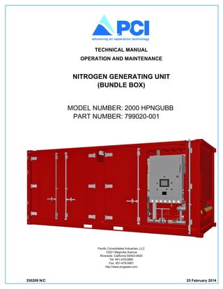
  • 1. 350209 N/C 25 February 2014 TECHNICAL MANUAL OPERATION AND MAINTENANCE NITROGEN GENERATING UNIT (BUNDLE BOX) MODEL NUMBER: 2000 HPNGUBB PART NUMBER: 799020-001 Pacific Consolidated Industries, LLC 12201 Magnolia Avenue Riverside, California 92503-4820 Tel: 951-479-0860 Fax: 951-479-0861 http://www.pcigases.com
  • 2. Copyright  2014 by Pacific Consolidated Industries, LLC (PCI). This document contains confidential technical data, including trade secrets, proprietary to PCI. Disclosure of this data is expressly conditioned upon your assent that its use is limited to use within your company only (and does not include manufacture or processing uses). No part of this document may be used or reproduced in any form or by any means or stored in a database or retrieval system without written permission of PCI. Copying or directly reproducing any part of this manual for any purpose other than the original owner’s personal use is a violation of the United States Copyright laws. For more information and assistance in obtaining additional copies of this manual, contact Pacific Consolidated Industries, LLC, 12201 Magnolia Avenue, Riverside, California 92503-4820. This manual is presented as-is, without warranty of any kind, either expressed or implied, respecting its contents, including, but not limited to implied warranties for the manual’s quality. PCI is not liable to the purchaser or any other person or entity with respect to any liability, loss, or damage caused or alleged to have been caused directly or indirectly by this manual. Pacific Consolidated Industries assumes no responsibility for the accuracy, completeness or usefulness of this manual, or from any problems or conditions which may arise from the use of the information contained herein or omissions from this manual. Pacific Consolidated Industries reserves the right to change and update the information and specifications contained within this manual at any time without notice. REVISION DATE DESCRIPTION DCN N/C 25 Feb 2014 Initial Release 3721
  • 3. TABLE OF CONTENTS PARAGRAPH PAGE 350209 i Nitrogen Generating Unit 2000 HPNGUBB Foreword. . . . . . . . . . . . . . . . . . . . . . . . . . . . . . . . . . . . . . . . . . . . . . . . . . . . . . . . . . . . . . . . . . . . . . . . . . . . vii Safety Summary . . . . . . . . . . . . . . . . . . . . . . . . . . . . . . . . . . . . . . . . . . . . . . . . . . . . . . . . . . . . . . . . . . . . . . ix 1 INTRODUCTION 1.1 Scope . . . . . . . . . . . . . . . . . . . . . . . . . . . . . . . . . . . . . . . . . . . . . . . . . . . . . . . . . . . . . . . . . . . . . . . . . . . . . . 1-1 1.2 Operation . . . . . . . . . . . . . . . . . . . . . . . . . . . . . . . . . . . . . . . . . . . . . . . . . . . . . . . . . . . . . . . . . . . . . . . . . . . 1-1 1.3 Equipment Description . . . . . . . . . . . . . . . . . . . . . . . . . . . . . . . . . . . . . . . . . . . . . . . . . . . . . . . . . . . . . . . . . 1-1 1.3.1 Major Components. . . . . . . . . . . . . . . . . . . . . . . . . . . . . . . . . . . . . . . . . . . . . . . . . . . . . . . . . . . . . . . . . . . . 1-1 1.4 Associated Technical Documentation . . . . . . . . . . . . . . . . . . . . . . . . . . . . . . . . . . . . . . . . . . . . . . . . . . . . . 1-1 1.5 Leading Particulars . . . . . . . . . . . . . . . . . . . . . . . . . . . . . . . . . . . . . . . . . . . . . . . . . . . . . . . . . . . . . . . . . . . 1-3 1.6 Bundle Box Access Doors . . . . . . . . . . . . . . . . . . . . . . . . . . . . . . . . . . . . . . . . . . . . . . . . . . . . . . . . . . . . . . 1-4 1.7 Acronyms and Abbreviations . . . . . . . . . . . . . . . . . . . . . . . . . . . . . . . . . . . . . . . . . . . . . . . . . . . . . . . . . . . . 1-5 2 PREPARATION FOR USE, SHIPMENT AND STORAGE 2.1 Preparation for Use . . . . . . . . . . . . . . . . . . . . . . . . . . . . . . . . . . . . . . . . . . . . . . . . . . . . . . . . . . . . . . . . . . . 2-1 2.1.1 Site Conditions . . . . . . . . . . . . . . . . . . . . . . . . . . . . . . . . . . . . . . . . . . . . . . . . . . . . . . . . . . . . . . . . . . . . . . . 2-1 2.1.2 Installation . . . . . . . . . . . . . . . . . . . . . . . . . . . . . . . . . . . . . . . . . . . . . . . . . . . . . . . . . . . . . . . . . . . . . . . . . . 2-1 2.1.3 External Equipment Hookup . . . . . . . . . . . . . . . . . . . . . . . . . . . . . . . . . . . . . . . . . . . . . . . . . . . . . . . . . . . . 2-3 2.1.3.1 Electrical Power Hookup . . . . . . . . . . . . . . . . . . . . . . . . . . . . . . . . . . . . . . . . . . . . . . . . . . . . . . . . . . . . . . . 2-3 2.1.4 Container Lighting . . . . . . . . . . . . . . . . . . . . . . . . . . . . . . . . . . . . . . . . . . . . . . . . . . . . . . . . . . . . . . . . . . . . 2-4 2.2 Preparation for Shipment or Storage . . . . . . . . . . . . . . . . . . . . . . . . . . . . . . . . . . . . . . . . . . . . . . . . . . . . . . 2-5 2.2.1 Preparation For Shipment . . . . . . . . . . . . . . . . . . . . . . . . . . . . . . . . . . . . . . . . . . . . . . . . . . . . . . . . . . . . . . 2-5 2.2.2 Preparation For Storage. . . . . . . . . . . . . . . . . . . . . . . . . . . . . . . . . . . . . . . . . . . . . . . . . . . . . . . . . . . . . . . . 2-8 2.2.2.1 Storage Facility . . . . . . . . . . . . . . . . . . . . . . . . . . . . . . . . . . . . . . . . . . . . . . . . . . . . . . . . . . . . . . . . . . . . . . 2-9 2.2.2.2 Outdoor Storage. . . . . . . . . . . . . . . . . . . . . . . . . . . . . . . . . . . . . . . . . . . . . . . . . . . . . . . . . . . . . . . . . . . . . . 2-9 3 OPERATION 3.1 Controls and Indicators . . . . . . . . . . . . . . . . . . . . . . . . . . . . . . . . . . . . . . . . . . . . . . . . . . . . . . . . . . . . . . . . 3-1 3.2 Pre-Operation Instructions . . . . . . . . . . . . . . . . . . . . . . . . . . . . . . . . . . . . . . . . . . . . . . . . . . . . . . . . . . . . . . 3-2 3.3 Operation . . . . . . . . . . . . . . . . . . . . . . . . . . . . . . . . . . . . . . . . . . . . . . . . . . . . . . . . . . . . . . . . . . . . . . . . . . . 3-6 3.3.1 Operation Adjustments. . . . . . . . . . . . . . . . . . . . . . . . . . . . . . . . . . . . . . . . . . . . . . . . . . . . . . . . . . . . . . . . 3-10 3.4 Data Logging . . . . . . . . . . . . . . . . . . . . . . . . . . . . . . . . . . . . . . . . . . . . . . . . . . . . . . . . . . . . . . . . . . . . . . . 3-12 3.4.1 Data Logging Software Installation . . . . . . . . . . . . . . . . . . . . . . . . . . . . . . . . . . . . . . . . . . . . . . . . . . . . . . 3-13 3.4.1.1 Windows 98/2000/XP® & Excel® 2003 . . . . . . . . . . . . . . . . . . . . . . . . . . . . . . . . . . . . . . . . . . . . . . . . . . . 3-13 3.4.1.2 Windows 7® & Excel® 2010 . . . . . . . . . . . . . . . . . . . . . . . . . . . . . . . . . . . . . . . . . . . . . . . . . . . . . . . . . . . 3-14 3.4.2 Log The Data . . . . . . . . . . . . . . . . . . . . . . . . . . . . . . . . . . . . . . . . . . . . . . . . . . . . . . . . . . . . . . . . . . . . . . . 3-16 3.5 Performance. . . . . . . . . . . . . . . . . . . . . . . . . . . . . . . . . . . . . . . . . . . . . . . . . . . . . . . . . . . . . . . . . . . . . . . . 3-17 3.5.1 Membrane Performance. . . . . . . . . . . . . . . . . . . . . . . . . . . . . . . . . . . . . . . . . . . . . . . . . . . . . . . . . . . . . . . 3-17 3.5.2 Flow vs Purity. . . . . . . . . . . . . . . . . . . . . . . . . . . . . . . . . . . . . . . . . . . . . . . . . . . . . . . . . . . . . . . . . . . . . . . 3-18 3.5.3 Performance Troubleshooting . . . . . . . . . . . . . . . . . . . . . . . . . . . . . . . . . . . . . . . . . . . . . . . . . . . . . . . . . . 3-19 3.6 Shut-Down . . . . . . . . . . . . . . . . . . . . . . . . . . . . . . . . . . . . . . . . . . . . . . . . . . . . . . . . . . . . . . . . . . . . . . . . . 3-20 3.6.1 Emergency Stop. . . . . . . . . . . . . . . . . . . . . . . . . . . . . . . . . . . . . . . . . . . . . . . . . . . . . . . . . . . . . . . . . . . . . 3-21 4 THEORY OF OPERATION 4.1 Nitrogen Production . . . . . . . . . . . . . . . . . . . . . . . . . . . . . . . . . . . . . . . . . . . . . . . . . . . . . . . . . . . . . . . . . . . 4-1 4.2 Operation Components . . . . . . . . . . . . . . . . . . . . . . . . . . . . . . . . . . . . . . . . . . . . . . . . . . . . . . . . . . . . . . . . 4-2 4.2.1 Feed Air and Discharge Operation Components . . . . . . . . . . . . . . . . . . . . . . . . . . . . . . . . . . . . . . . . . . . . . 4-3
  • 4. PARAGRAPH PAGE ii 350209 Nitrogen Generating Unit 2000 HPNGUBB 4.2.2 Filter Tower Components . . . . . . . . . . . . . . . . . . . . . . . . . . . . . . . . . . . . . . . . . . . . . . . . . . . . . . . . . . . . . . .4-4 4.2.3 Membrane Assembly Components . . . . . . . . . . . . . . . . . . . . . . . . . . . . . . . . . . . . . . . . . . . . . . . . . . . . . . . .4-6 4.2.4 Other Operation Components . . . . . . . . . . . . . . . . . . . . . . . . . . . . . . . . . . . . . . . . . . . . . . . . . . . . . . . . . . . .4-8 4.2.5 Electrical Enclosure Components . . . . . . . . . . . . . . . . . . . . . . . . . . . . . . . . . . . . . . . . . . . . . . . . . . . . . . . . .4-9 5 CALIBRATION 5.1 Calibration and Verification . . . . . . . . . . . . . . . . . . . . . . . . . . . . . . . . . . . . . . . . . . . . . . . . . . . . . . . . . . . . . .5-1 5.1.1 Calibration and Verification Intervals . . . . . . . . . . . . . . . . . . . . . . . . . . . . . . . . . . . . . . . . . . . . . . . . . . . . . . .5-1 5.1.2 Calibration Definitions . . . . . . . . . . . . . . . . . . . . . . . . . . . . . . . . . . . . . . . . . . . . . . . . . . . . . . . . . . . . . . . . . .5-1 5.1.3 Calibration Data SHeets and Records. . . . . . . . . . . . . . . . . . . . . . . . . . . . . . . . . . . . . . . . . . . . . . . . . . . . . .5-2 5.1.4 Calibration Device Information. . . . . . . . . . . . . . . . . . . . . . . . . . . . . . . . . . . . . . . . . . . . . . . . . . . . . . . . . . . .5-3 5.1.5 Calibration Environmental Conditions . . . . . . . . . . . . . . . . . . . . . . . . . . . . . . . . . . . . . . . . . . . . . . . . . . . . . .5-3 5.1.6 Calibration Measurement Equipment Requirements. . . . . . . . . . . . . . . . . . . . . . . . . . . . . . . . . . . . . . . . . . .5-3 5.1.7 Calibration Support Equipment . . . . . . . . . . . . . . . . . . . . . . . . . . . . . . . . . . . . . . . . . . . . . . . . . . . . . . . . . . .5-4 5.2 Resistance Temperature Detector (RTD) Verification . . . . . . . . . . . . . . . . . . . . . . . . . . . . . . . . . . . . . . . . . .5-4 5.2.1 RTD-7 Amplifier Calibration. . . . . . . . . . . . . . . . . . . . . . . . . . . . . . . . . . . . . . . . . . . . . . . . . . . . . . . . . . . . . .5-6 5.3 Flowmeter Verification . . . . . . . . . . . . . . . . . . . . . . . . . . . . . . . . . . . . . . . . . . . . . . . . . . . . . . . . . . . . . . . . . .5-7 5.3.1 Flowmeter (MFT-1) . . . . . . . . . . . . . . . . . . . . . . . . . . . . . . . . . . . . . . . . . . . . . . . . . . . . . . . . . . . . . . . . . . . .5-7 5.3.1.1 Flowmeter (MFT-1) Instllation . . . . . . . . . . . . . . . . . . . . . . . . . . . . . . . . . . . . . . . . . . . . . . . . . . . . . . . . . . .5-10 5.4 O2 Sensor Calibration (NA-1) . . . . . . . . . . . . . . . . . . . . . . . . . . . . . . . . . . . . . . . . . . . . . . . . . . . . . . . . . . .5-11 6 MAINTENANCE 6.1 Maintenance Responsibility. . . . . . . . . . . . . . . . . . . . . . . . . . . . . . . . . . . . . . . . . . . . . . . . . . . . . . . . . . . . . .6-1 6.1.1 Maintenance Data Sheets and Records . . . . . . . . . . . . . . . . . . . . . . . . . . . . . . . . . . . . . . . . . . . . . . . . . . . .6-1 6.2 Tools and Test Equipment. . . . . . . . . . . . . . . . . . . . . . . . . . . . . . . . . . . . . . . . . . . . . . . . . . . . . . . . . . . . . . .6-1 6.2.1 Cleanliness . . . . . . . . . . . . . . . . . . . . . . . . . . . . . . . . . . . . . . . . . . . . . . . . . . . . . . . . . . . . . . . . . . . . . . . . . .6-2 6.3 Maintenance and Inspection Requirements . . . . . . . . . . . . . . . . . . . . . . . . . . . . . . . . . . . . . . . . . . . . . . . . .6-2 6.3.1 Replacement Intervals. . . . . . . . . . . . . . . . . . . . . . . . . . . . . . . . . . . . . . . . . . . . . . . . . . . . . . . . . . . . . . . . . .6-2 6.4 Touch-Up Paint . . . . . . . . . . . . . . . . . . . . . . . . . . . . . . . . . . . . . . . . . . . . . . . . . . . . . . . . . . . . . . . . . . . . . . .6-3 6.5 General Overhaul Instructions. . . . . . . . . . . . . . . . . . . . . . . . . . . . . . . . . . . . . . . . . . . . . . . . . . . . . . . . . . . .6-3 6.6 Seal Replacement . . . . . . . . . . . . . . . . . . . . . . . . . . . . . . . . . . . . . . . . . . . . . . . . . . . . . . . . . . . . . . . . . . . . .6-4 6.7 CPU and Touch Screen Battery Replacement . . . . . . . . . . . . . . . . . . . . . . . . . . . . . . . . . . . . . . . . . . . . . . .6-5 6.7.1 CPU Battery Replacement. . . . . . . . . . . . . . . . . . . . . . . . . . . . . . . . . . . . . . . . . . . . . . . . . . . . . . . . . . . . . . .6-6 6.7.2 Touch Screen Battery Replacement . . . . . . . . . . . . . . . . . . . . . . . . . . . . . . . . . . . . . . . . . . . . . . . . . . . . . . .6-6 6.8 Post Maintenance, Service and Repair Examination. . . . . . . . . . . . . . . . . . . . . . . . . . . . . . . . . . . . . . . . . . .6-7 Appendix A Flow Diagram - - - - - - - - - - - - - - - - - - - - - - - - - - - - - - - - - - - - - - - - - A-1 Appendix B Membrane Performance Tables - - - - - - - - - - - - - - - - - - - - - - - - - - - - - - - - - B-1 Appendix C Process and Insrtumentaion Diagram with Bill of Materials - - - - - - - - - - - - - - - - - - - C-1 Appendix D Electrical Schematic with Bill of Materials - - - - - - - - - - - - - - - - - - - - - - - - - - - - D-1 Appendix E Control Screens - - - - - - - - - - - - - - - - - - - - - - - - - - - - - - - - - - - - - - - - E-1 Appendix F Spare Parts - - - - - - - - - - - - - - - - - - - - - - - - - - - - - - - - - - - - - - - - - - F-1
  • 5. LIST OF ILLUSTRATIONS FIGURE PAGE 350209 iii Nitrogen Generating Unit 2000 HPNGUBB 1-1 Major Components - - - - - - - - - - - - - - - - - - - - - - - - - - - - - - - - - - - - - - - - - - 1-2 1-2 Access Doors - - - - - - - - - - - - - - - - - - - - - - - - - - - - - - - - - - - - - - - - - - - - - 1-4 2-1 Bundle Box Ports - - - - - - - - - - - - - - - - - - - - - - - - - - - - - - - - - - - - - - - - - - - 2-2 2-2 Electrical Enclosure Back Panel (Transformer (XFR-1)- - - - - - - - - - - - - - - - - - - - - - - - - 2-4 2-3 Bundle Box Operator Control Panel - - - - - - - - - - - - - - - - - - - - - - - - - - - - - - - - - - 2-5 2-4 Discharge Plumbing- - - - - - - - - - - - - - - - - - - - - - - - - - - - - - - - - - - - - - - - - - 2-6 2-5 Separator and Filter Drains - - - - - - - - - - - - - - - - - - - - - - - - - - - - - - - - - - - - - - 2-7 2-6 Feed Air Plumbing - - - - - - - - - - - - - - - - - - - - - - - - - - - - - - - - - - - - - - - - - - 2-8 2-7 Outdoor Storage Preparation - - - - - - - - - - - - - - - - - - - - - - - - - - - - - - - - - - - - - 2-10 3-1 Operator Panel - - - - - - - - - - - - - - - - - - - - - - - - - - - - - - - - - - - - - - - - - - - - 3-1 3-2 Feed Valves - - - - - - - - - - - - - - - - - - - - - - - - - - - - - - - - - - - - - - - - - - - - - 3-3 3-3 Discharge Valves - - - - - - - - - - - - - - - - - - - - - - - - - - - - - - - - - - - - - - - - - - - 3-4 3-4 Filter Drain Valves - - - - - - - - - - - - - - - - - - - - - - - - - - - - - - - - - - - - - - - - - - 3-4 3-5 Membrane Inlet Valves - - - - - - - - - - - - - - - - - - - - - - - - - - - - - - - - - - - - - - - - 3-5 3-6 Operator Process Controls and Valves - - - - - - - - - - - - - - - - - - - - - - - - - - - - - - - - 3-6 3-7 NGU Screen - - - - - - - - - - - - - - - - - - - - - - - - - - - - - - - - - - - - - - - - - - - - - 3-7 3-8 Differential Gauges (DPG-1 - 4) - - - - - - - - - - - - - - - - - - - - - - - - - - - - - - - - - - - - 3-9 3-9 Setup Screen - - - - - - - - - - - - - - - - - - - - - - - - - - - - - - - - - - - - - - - - - - - - - 3-10 3-10 Ethernet Port on the Operator Panel- - - - - - - - - - - - - - - - - - - - - - - - - - - - - - - - - - 3-17 3-11 Feed Air Valves - - - - - - - - - - - - - - - - - - - - - - - - - - - - - - - - - - - - - - - - - - - - 3-20 3-12 Discharge Valves - - - - - - - - - - - - - - - - - - - - - - - - - - - - - - - - - - - - - - - - - - - 3-21 3-13 Inlet Air Shut-Down (ISV-1) - - - - - - - - - - - - - - - - - - - - - - - - - - - - - - - - - - - - - - 3-22 4-1 Feed Air and Discharge Operation Components - - - - - - - - - - - - - - - - - - - - - - - - - - - - 4-2 4-2 Filter Tower Operation Components - - - - - - - - - - - - - - - - - - - - - - - - - - - - - - - - - - 4-4 4-3 Membrane Assembly Components (inlet plumbing) - - - - - - - - - - - - - - - - - - - - - - - - - - 4-6 4-4 Membrane Assembly Components (outlet plumbing)- - - - - - - - - - - - - - - - - - - - - - - - - - 4-7 4-5 Other Operation Components - - - - - - - - - - - - - - - - - - - - - - - - - - - - - - - - - - - - - 4-8 4-6 Electrical Enclosure Components - - - - - - - - - - - - - - - - - - - - - - - - - - - - - - - - - - - 4-11 5-1 RTD and PT Locations - - - - - - - - - - - - - - - - - - - - - - - - - - - - - - - - - - - - - - - - 5-5 5-2 RTD-7 Amplifier Test Setup - - - - - - - - - - - - - - - - - - - - - - - - - - - - - - - - - - - - - - 5-6 5-3 Discharge Plumbing- - - - - - - - - - - - - - - - - - - - - - - - - - - - - - - - - - - - - - - - - - 5-8 5-4 Flowmeter (MFT-1) Assembly - - - - - - - - - - - - - - - - - - - - - - - - - - - - - - - - - - - - - 5-9 5-5 PCV-1 Removal from MFT-1 Assembly - - - - - - - - - - - - - - - - - - - - - - - - - - - - - - - - 5-10 5-6 Eight Bolt (nuts) Torque Pattern - - - - - - - - - - - - - - - - - - - - - - - - - - - - - - - - - - - - 5-11 5-7 Sample Valve (BV-19) - - - - - - - - - - - - - - - - - - - - - - - - - - - - - - - - - - - - - - - - 5-12 6-1 Electrical Enclosure (open) - - - - - - - - - - - - - - - - - - - - - - - - - - - - - - - - - - - - - - 6-5 6-2 CPU Battery Removal/Installation - - - - - - - - - - - - - - - - - - - - - - - - - - - - - - - - - - - 6-6 6-3 Touch Screen (rear view) - - - - - - - - - - - - - - - - - - - - - - - - - - - - - - - - - - - - - - - 6-7 A-1 Flow Diagram - - - - - - - - - - - - - - - - - - - - - - - - - - - - - - - - - - - - - - - - - - - - - A-2 FO-1. Process and Instrumentation Diagram (P&ID) {Sheet 1 of 3} - - - - - - - - - - - - - - - - - - - - - - C-7 FO-2. Electrical Schematic (Sheet 1 of 7) - - - - - - - - - - - - - - - - - - - - - - - - - - - - - - - - - - D-7 E-1 NGU Screen (Auto Flow and Purity Disabled) - - - - - - - - - - - - - - - - - - - - - - - - - - - - - E-2 E-2 NGU Screen (Auto Flow or Purity Enabled) - - - - - - - - - - - - - - - - - - - - - - - - - - - - - - E-3 E-3 Setup Screen (Manual Mode Set) - - - - - - - - - - - - - - - - - - - - - - - - - - - - - - - - - - - E-4 E-4 Setup Screen (Auto Off-Spec and Auto Flow Enabled) - - - - - - - - - - - - - - - - - - - - - - - - - E-5
  • 6. FIGURE PAGE iv 350209 Nitrogen Generating Unit 2000 HPNGUBB E-5 Setup Screen (Auto Off-Spec and Auto Purity Enabled) - - - - - - - - - - - - - - - - - - - - - - - - E-6 E-6 Alarm History Screen - - - - - - - - - - - - - - - - - - - - - - - - - - - - - - - - - - - - - - - - - E-7 E-7 Information Screen - - - - - - - - - - - - - - - - - - - - - - - - - - - - - - - - - - - - - - - - - - E-7
  • 7. LIST OF TABLES TABLE PAGE 350209 v/(vi blank) Nitrogen Generating Unit 2000 HPNGUBB 1-1 Leading Particulars . . . . . . . . . . . . . . . . . . . . . . . . . . . . . . . . . . . . . . . . . . . . . . . . . . . . . . . . . . . . . . . . . . . 1-3 1-2 Access Doors . . . . . . . . . . . . . . . . . . . . . . . . . . . . . . . . . . . . . . . . . . . . . . . . . . . . . . . . . . . . . . . . . . . . . . . . 1-5 3-1 Operator Panel. . . . . . . . . . . . . . . . . . . . . . . . . . . . . . . . . . . . . . . . . . . . . . . . . . . . . . . . . . . . . . . . . . . . . . . 3-2 3-2 Default Setpoints . . . . . . . . . . . . . . . . . . . . . . . . . . . . . . . . . . . . . . . . . . . . . . . . . . . . . . . . . . . . . . . . . . . . . 3-7 3-3 Operating Parameters . . . . . . . . . . . . . . . . . . . . . . . . . . . . . . . . . . . . . . . . . . . . . . . . . . . . . . . . . . . . . . . . . 3-8 3-4 Memory Map . . . . . . . . . . . . . . . . . . . . . . . . . . . . . . . . . . . . . . . . . . . . . . . . . . . . . . . . . . . . . . . . . . . . . . . 3-16 3-5 Performance Troubleshooting . . . . . . . . . . . . . . . . . . . . . . . . . . . . . . . . . . . . . . . . . . . . . . . . . . . . . . . . . . 3-19 4-1 Feed Air and Discharge Operation Components . . . . . . . . . . . . . . . . . . . . . . . . . . . . . . . . . . . . . . . . . . . . . 4-3 4-2 Filter Tower Operation Components . . . . . . . . . . . . . . . . . . . . . . . . . . . . . . . . . . . . . . . . . . . . . . . . . . . . . . 4-5 4-3 Membrane Assembly Components . . . . . . . . . . . . . . . . . . . . . . . . . . . . . . . . . . . . . . . . . . . . . . . . . . . . . . . 4-7 4-4 Other Operation Components . . . . . . . . . . . . . . . . . . . . . . . . . . . . . . . . . . . . . . . . . . . . . . . . . . . . . . . . . . . 4-9 4-5 Electrical Enclosure Components . . . . . . . . . . . . . . . . . . . . . . . . . . . . . . . . . . . . . . . . . . . . . . . . . . . . . . . . 4-9 5-1 Devices Requiring Calibration or Verification. . . . . . . . . . . . . . . . . . . . . . . . . . . . . . . . . . . . . . . . . . . . . . . . 5-1 5-2 Initial Calibration and Verification Intervals . . . . . . . . . . . . . . . . . . . . . . . . . . . . . . . . . . . . . . . . . . . . . . . . . 5-1 5-3 Calibration Measurement Equipment. . . . . . . . . . . . . . . . . . . . . . . . . . . . . . . . . . . . . . . . . . . . . . . . . . . . . . 5-3 6-1 Component Replacement Intervals . . . . . . . . . . . . . . . . . . . . . . . . . . . . . . . . . . . . . . . . . . . . . . . . . . . . . . . 6-3 B-1 Membrane Inlet Pressure vs Flow @ 95% Purity (50 (6 inch) Membranes) . . . . . . . . . . . . . . . . . . . . . . . . B-2 B-2 Number of Membranes vs Flow @ 95% Purity (0 - 50 (6 inch) Membranes) . . . . . . . . . . . . . . . . . . . . . . . B-3 B-3 Membrane Inlet Temperature vs Produced N2 Flow . . . . . . . . . . . . . . . . . . . . . . . . . . . . . . . . . . . . . . . . . . B-4 B-4 Membrane Pressure Temperautre Curve. . . . . . . . . . . . . . . . . . . . . . . . . . . . . . . . . . . . . . . . . . . . . . . . . . . B-5 C-1 P&ID Bill of Materials . . . . . . . . . . . . . . . . . . . . . . . . . . . . . . . . . . . . . . . . . . . . . . . . . . . . . . . . . . . . . . . . . . C-2 D-1 Electrical Bill of Materials . . . . . . . . . . . . . . . . . . . . . . . . . . . . . . . . . . . . . . . . . . . . . . . . . . . . . . . . . . . . . . . D-2 F-1 Filter Consumable Spare Parts List . . . . . . . . . . . . . . . . . . . . . . . . . . . . . . . . . . . . . . . . . . . . . . . . . . . . . . . F-2 F-2 Pnuematic Capital Spare Parts List . . . . . . . . . . . . . . . . . . . . . . . . . . . . . . . . . . . . . . . . . . . . . . . . . . . . . . . F-2 F-3 Electrical Enclosure Capital Spare Parts List. . . . . . . . . . . . . . . . . . . . . . . . . . . . . . . . . . . . . . . . . . . . . . . . F-3 F-4 Programmed Devices Spare Parts List . . . . . . . . . . . . . . . . . . . . . . . . . . . . . . . . . . . . . . . . . . . . . . . . . . . . F-3 F-5 CPU and Touch Screen Spare Parts List. . . . . . . . . . . . . . . . . . . . . . . . . . . . . . . . . . . . . . . . . . . . . . . . . . . F-3 F-6 PLC Modules Parts List . . . . . . . . . . . . . . . . . . . . . . . . . . . . . . . . . . . . . . . . . . . . . . . . . . . . . . . . . . . . . . . . F-4 F-7 Tools Parts List . . . . . . . . . . . . . . . . . . . . . . . . . . . . . . . . . . . . . . . . . . . . . . . . . . . . . . . . . . . . . . . . . . . . . . F-4
  • 8.
  • 9. 350209 vii/(viii blank) Nitrogen Generating Unit 2000 HPNGUBB FOREWORD PARTS AND SERVICE INFORMATION To enable Pacific Consolidated Industries (PCI) to provide better service and support, make sure you have the following information regarding your equipment: Equipment Name/Nomenclature Part Number Serial Number Date of Manufacture All of this information can be obtained from the Equipment Data Plate located directly on the equipment. When requesting information and availability for specific parts for your equipment, make sure you have the following information: PCI Part Number Drawing Number (if available) Item Number on Drawing (if available) OEM Part Number (if available) CONTACT PCI FOR PARTS AND SERVICE Pacific Consolidated Industries parts, service, warranty and field support can be obtained contacting Product Support, by phone or fax using the following telephone numbers: Toll Free: (800) 309-8935 Voice: (951) 479-0860 Fax: (951) 479-0864 Or contact us on the internet using our Support web page at: http://www.pcigases.com
  • 10.
  • 11. 350209 ix Nitrogen Generating Unit 2000 HPNGUBB SAFETY SUMMARY This safety summary contains general safety warnings that must be understood and applied during operation and maintenance of this equipment. Failure to obey these precautions could result in serious injury or death to personnel and damage to the equipment. When first aid is required refer to OSHA Standard 1910.151. These are the safety and hazardous material icons used within the manual: Highlights an essential operating or maintenance procedure, practice, condition, statement, etc. which, if not strictly observed, could result in injury to, or death of, personnel or long term health hazards. Highlights an essential operating or maintenance procedure, practice, condition, statement, etc. which, if not strictly observed, could result in damage to, or destruction of, equipment or loss of mission effectiveness. NOTE Highlights an essential operating or maintenance procedure, condition or statement. Make sure you read the information in the warnings, cautions and notes carefully. Consult someone experienced in handling oxygen equipment about any unclear issues. Warnings shall precede cautions, which in-turn shall precede notes. Warnings and cautions precede the step for which they are intended; notes follow the step. Additional safety guidelines related to specific components of the unit are described in the following chapters. GENERAL SAFETY The following general safety precautions are not related to any specific procedure. These are the minimum precautions that personnel must understand and apply at all times. HIGH VOLTAGE ELECTRICAL SUPPLY Do not replace components or make mechanical adjustments when electrical power is applied. Remove electrical power and use test equipment to make sure an electrical circuit is at ground potential or zero volts before doing maintenance, service or repair. OPERATOR SAFETY Potentially dangerous maintenance, service or repair tasks must be done with someone who is capable of giving aid.
  • 12. x 350209 Nitrogen Generating Unit 2000 HPNGUBB EQUIPMENT LOCK-OUT/TAG-OUT Before doing maintenance, service or repair, make sure the equipment has been correctly locked-out and tagged-out. Lock-out is blocking the flow of energy from a power source to the equipment. Power sources include:  Electrical Power  Compressed Air  Vacuum  Other High Pressure Gases  Pressurized Fluid  Vessels and Lines Containing Pressurized Fluid  Thermal Power  Pressurized Water  Gravity and External Loads  Accumulators  Water Under Pressure Lock-out is installing a lockable device (padlock) at the energy source making sure equipment cannot be powered-up, started, moved or operated. The lock and key must be assigned to authorized personnel. Tag-out is installing an identification tag on the power source directly on the lock-out. The tag must show a warning not to restore power and clearly indicate, Do Not Operate Equipment. Identification of the person or group applying the tag-out is required. Both the lock-out and tag-out must be strong enough to prevent unauthorized removal and be resistant to the environment. Personnel doing the lock-out and tag-out must:  Correctly shut-down and isolate the equipment  Install lock-out/tag-out devices  Safely release stored energy  Make sure all energy and power has been removed After maintenance or service, the person that applied the lock-out/tag-out must:  Remove lock-out/tag-out devices  Safely apply energy and power sources  Make sure the equipment is clear and ready to run safely  Safely start-up the equipment. FILTER ELEMENT DISPOSAL Used or contaminated filter elements and absorbent materials must be discarded correctly as a waste material or recycled.
  • 13. 350209 xi Nitrogen Generating Unit 2000 HPNGUBB COMPRESSED AIR AND NITROGEN Compressed air and nitrogen is very hazardous when not contained. When using compressed air, use protective equipment, goggles or face shields. Do not direct air or nitrogen streams toward yourself or other personnel. HEAVY OBJECTS The equipment, elements and components include heavy items. Make sure lifting slings and hoist equipment have correct load ratings before you use them. Do not try to lift heavy equipment without using lifting devices. Do not use chain to lift heavy equipment; use wire rope or braided slings. Wear thick leather gloves when handling wire rope, wire rope slings or crane lines. EQUIPMENT AT HEIGHTS When equipment is installed at elevated heights, make sure maintenance, service and repair on the equipment is done from stable work platforms and surfaces. Use support equipment; man-lifts, ladders, scaffolding or slings. When working at heights, use safety harnesses and fall restraint equipment to prevent injury or death. When working from ladders:  Do not climb above the last three steps of the ladder.  Do not over extend your reach.  Make sure the ladder is correctly installed on a flat and level surface and at an angle preventing it from sliding or moving. When working under equipment, make sure the equipment overhead is secured where no movement can occur. If other work is being done above:  Wear a hard hat.  Erect temporary overhead shields to prevent falling objects from hitting personnel. Small items dropped from high above can cause serious injury or even death when contact is made with personnel below. HOT SURFACES Do not handle or touch hot parts with bare hands or exposed skin. Do not touch the filtration and separation unit heater or the tubing runs with bare hands or exposed skin. Use thermal insulated or thick leather gloves when handling hot equipment and components. Wait for the equipment to cool-down before doing maintenance, service or repair. Hot surfaces include:  Heat exchanger bodies  Cooling fins and interconnecting lines  Heaters NOTE Stainless steel tubing does not show signs of high temperatures.
  • 14. xii 350209 Nitrogen Generating Unit 2000 HPNGUBB NOISY EQUIPMENT Normal equipment operation can create high noise levels. Wear ear protection when operating, servicing or repairing the equipment. ENCLOSURE DOORS, COVERS AND GUARDS Secure enclosure doors, component covers and equipment guards immediately after completion of maintenance, service, repair or calibration. Do not operate equipment with enclosure doors open or component covers and equipment guards removed unless instructed otherwise. EQUIPMENT OPERATION Follow the PCI recommended Operating Procedures or other pre-approved instructions and procedures supplied by supplemental manuals or bulletins. Operators must be trained and know all operating procedures, operational characteristics of the equipment and the functions and equipment operation. Do not operate the equipment above rated capacity or in adverse environmental conditions. During operation, make sure the equipment is not accidentally overloaded due to incorrect adjustment of controls. NITROGEN ASPHYXIATION When working in the bundle box:  Make sure container doors are open.  Do not stand near a leaky nitrogen gas line, component or pressure vessel.  Do not maintain, inspect, service or repair the equipment alone.  Do not smoke in or near the container. OXYGEN ENRICHED EXHAUST AIR When working on top of the bundle box where the oxygen enriched air is vented:  Do not smoke next to the oxygen exhaust outlet.  Do not allow other ignition sources near the oxygen exhaust outlet; sparks, open flame, extremely hot surfaces, etc.  Do not allow organic materials (oils, lubricants and other petroleum-based products) to be open to oxygen enriched exhaust air. PNEUMATIC SAFETY When working with high pressure gases and compressed air:  Make sure the line pressure is zero before disconnecting pneumatic lines.  Make sure all air receivers, pressure vessels, pneumatic lines and pneumatic components are bled- down and vented before doing maintenance.  Make sure all pressure vessels are vented to atmosphere before opening access hatches.  Block and restrain equipment under load before disconnecting pneumatic actuators.  Never torque leaking connections or fittings while lines are pressurized.  Eye and ear protection must be worn when operating or troubleshooting pneumatic systems.
  • 15. 350209 xiii Nitrogen Generating Unit 2000 HPNGUBB  Do not stand or work near pneumatic relief valves during operation.  Do not open a vent valve when other personnel are near the outlet.  When venting or discharging gas from a receiver, component or gas bottle, wear eye protection.  Do not allow pressurized gas to escape fast.  When doing work on or around extended pneumatic cylinders, protect the rod surfaces to prevent damage to the sealing surface.  Use eye protection and leather gloves when looking for leaks.  Do not look for leaks using your hand.  Prevent contaminants from entering the pneumatic system.  Change pneumatic supply filters on a regularly scheduled basis.  Do not exceed pneumatic supply pressures on circuits and equipment. ELECTRICAL SAFETY When working with electrical equipment:  Personnel must know the hazards and dangers of electrical work.  Only qualified personnel shall do electrical work.  Do not tamper with any electrical/mechanical interlocks or safety devices.  Do not alter, disable or bypass system safety devices.  Do not service or adjust any electrical circuit alone.  Make sure another qualified person is present that can give aid and knows the emergency shut- down procedures.  Turn-off all electrical circuits at the main isolation switch before working on any electrical circuit.  Put warning tags and lock-outs on open circuits and circuit breakers to prevent accidental application of power.  Wear suitable clothing while working within four feet of exposed electrical equipment.  Do Not wear rings, wristwatches or clothing with exposed metal buttons, zippers or fasteners.  Do Not work on electrical circuits near water or in wet conditions.  When calibrating, use insulated tools that have insulation down to the tool tip.  Make sure terminals and wires are not bridged, touched together or shorted during service and calibration.  Do not remove electronic or instrumentation modules or cards with power applied.  Do not disconnect electronic connectors with power applied. HEAT EXCHANGERS When servicing a Heat Exchanger:  The air cooled heat exchangers have thin metal cooling fins which must remain separated for air flow through the heat exchanger.  Make sure the heat exchanger cooling fins are free of dirt and debris. OWNER/OPERATOR RESPONSIBILITIES Do regular repair and maintenance tasks while the equipment is in service.
  • 16. xiv 350209 Nitrogen Generating Unit 2000 HPNGUBB MAINTENANCE AND SERVICE  Maintain, service and repair all installed equipment.  Keep records of all work done on the NGU.  Do all maintenance requirements at scheduled intervals.  Restore failed, malfunctioning, incorrectly adjusted or calibrated, worn out or in disrepair equipment and components before NGU operation.  Use trained and experienced personnel with knowledge of specific requirements, ratings and limitations for doing equipment maintenance, service and repair. SAFETY AND TRAINING  Do Not by-pass or override safety interlocks and devices.  Do Not operate equipment in a malfunctioning or unsafe condition.  Train all Operators and Technicians on the operation of every piece of equipment. COMPONENTS AND EQUIPMENT  Install all components requiring replacement with identical components including materials and seals.  Make sure all component substitutions are permitted by PCI before use.  Make sure all adjustable components and equipment set-points are within ratings and correct limits.  Use all equipment within component, equipment ratings and permitted limits.  Do Not operate NGU equipment under a warning condition.  Change all filter elements showing a dirty filter warning.
  • 17. 350209 1-1 Nitrogen Generating Unit 2000 HPNGUBB CHAPTER 1 INTRODUCTION 1.1 SCOPE This manual gives information and instruction for the operation and maintenance on the 20 foot Bundle Box, model number 2000 HPNGUBB manufactured by Pacific Consolidated Industries, LLC. This unit continuously filters clean dry air to produce up-to 95% pure dry gaseous Nitrogen with a flow rate up-to 2000 SCFM (57 SCMM) at a working pressure up-to 320 PSIG (22 Barg). 1.2 OPERATION This unit accepts after-cooled air up-to 365 psig (25 Barg) and routes it through a series of water, oil and particulate filters and separators. Cleaned dry air passes through air separation membranes leaving a high purity nitrogen discharge. The nitrogen gas routes through metering and flow devices before it is discharged for use or compression. 1.3 EQUIPMENT DESCRIPTION  Flow Diagram (refer to Appendix A on page A-1)  Membrane Performance Tables (refer to Appendix B on page B-1)  Process and Instrumentation Diagram (P&ID) with Bill of Materails (refer to Appendix C on page C-1)  Electrical Schematic with Bill of Materials (refer to Appendix D on page D-1)  Software Screens (refer to Appendix E on page E-1)  Spare Parts List (refer to Appendix F on page F-1)  Original Equipment Manufacturers (OEM) Manuals (refer to Attachments) 1.3.1 MAJOR COMPONENTS See Figure 1-1. on page 1-2 for location of the major components.  Inlet Shut-off Valve (IBV-1)  Water Separator (S-1)  Coalescing Water Separator (FLT-1)  Coalescing Filter (FLT-2)  Coalescing Ultra Fine Filter (FLT-3)  Heater (HTR-1)  Carbon Filter (FLT-4)  Unloader Valve (UL-1)  Nitrogen Analyzer (NA-1)  Membranes (MM-1 - MM-50)  Off-Spec Valve (OS-1)  Flow Meter (MFT-1)  Product Control Valve (PCV-1)  Flow Control Valve (FC-1) 1.4 ASSOCIATED TECHNICAL DOCUMENTATION Attached to this manual are the O&M manuals of the component manufactures.
  • 18. 1-2 350209 Nitrogen Generating Unit 2000 HPNGUBB Figure 1-1. Major Components FRONT VIEW MM-1 - 50 HTR-1 OS-1 MFT-1 BV-13 FC-1 PCV-1 REAR VIEW FLT-4 FLT-3 FLT-2 FLT-1 S-1 IBV-1 OS-1
  • 19. 350209 1-3 Nitrogen Generating Unit 2000 HPNGUBB 1.5 LEADING PARTICULARS Table 1-1. Leading Particulars PARTICULAR NOMENCLATURE Container Height 8.5 ft (2.6 m) Nominal Width 8.0 ft (2.4 m) Nominal Length 20 ft (6.1 m) Nominal Weight 15,000 lb (6,818 kg) Operating Environment Operating Site Outdoors Ambient Temperature 32 - 125°F (0 - 52°C) {70°F (21°C) No Degradation} Humidity Up-to 95% non-condensing Storage Environment Temperature -42 - 130°F (-41 - 55°C) Humidity Up-to 100% non-condensing Nitrogen Production (70°F (21°C) ambient, 100% Relative Humidity 500 ft (152 m) above sea level) Flow Rate Up-to 2000 SCFM (56 SCMM) Pressure Up-to 320 psig (22 Barg) Purity Up-to 95% Nitrogen Site Requirements Electrical Power Source 380 Vac, 3 phase, 50 Hz @ 151 FLA 415 Vac, 3 phase, 60 Hz @ 139 FLA 460 Vac, 3 phase, 60 Hz @ 125 FLA Feed Air Compressors 3500 SCFM @ 350 - 365 psig (99 SCMM @ 24 - 25 Barg) {12 mg/m3 oil content maximum} Membrane Separators Manufacturer Air Products Model PA6050-P3-8C-D2 Type Permeable membrane, hollow fiber tube Number of Membranes 50 Rated Pressure 350 psig (24 Barg) Nitrogen Purity Up-to 99% Oxygen Enriched Exhaust 25 - 40%
  • 20. 1-4 350209 Nitrogen Generating Unit 2000 HPNGUBB 1.6 BUNDLE BOX ACCESS DOORS Figure 1-2. and Table 1-2. on page 1-5 show and list the access doors and components accessed. Figure 1-2. Access Doors 1 2 3 4 5 FRONT VIEW REAR VIEW 6 7 8 9 10
  • 21. 350209 1-5 Nitrogen Generating Unit 2000 HPNGUBB 1.7 ACRONYMS AND ABBREVIATIONS CCW - - - - - - - - - - Counterclockwise CW- - - - - - - - - - - Clockwise Deg - - - - - - - - - - Degree Dia - - - - - - - - - - - Diameter FL - - - - - - - - - - - Flare FLA - - - - - - - - - - Full Load Ampere FNTP - - - - - - - - - Female National Pipe Thread FSA - - - - - - - - - - Full Scale Accuracy ID - - - - - - - - - - - Internal Diameter LG - - - - - - - - - - - Long MNPT - - - - - - - - - Male National Pipe Thread NC - - - - - - - - - - - Normally Closed NO - - - - - - - - - - - Normally Open Nom - - - - - - - - - - Nominal NPT - - - - - - - - - - National Pipe Thread OD - - - - - - - - - - - Outside Diameter PDT - - - - - - - - - - Pole Double Throw PL - - - - - - - - - - - Plate PPM - - - - - - - - - - Parts Per Million PTFE- - - - - - - - - - PolyTetraFluoroEthylene (Teflon®) Reg - - - - - - - - - - Regular SCFM - - - - - - - - - Standard Cubic Feet per Minute SCH - - - - - - - - - - Schedule SCMM - - - - - - - - - Standard Cubic Meters per Minute SPDT - - - - - - - - - Single Pole Double Throw Table 1-2. Access Doors ITEM DESCRIPTION COMPONENTS ACCESSED 1 Left Side Right Door MM-44 - 50 outlet hoses 2 Front Left Door CV-5 - 8 and Membrane Towers 3 & 4 outlet hoses 3 Front Middle Left Door CV-1 - 4 and Membrane Towers 1 & 2 outlet hoses 4 Front Middle Right Door BV-19, MFT-1, NV-1, OS-1, NV-1, PCV-1, PG-4 - 5 & PRV-1 - 2 5 Front Right Door BV-13 & 18, FC-1, ISV-1, Operator Panel 6 Rear Left Door BV-9 - 12, 14 - 17, DPG-1, FLT-1, IBV-1, NV-2 - 3, PG-6 - 9 & S-1 7 Rear Middle Left Door BPR-1, DPG-2 - 4, FLT-2 - 4, NV-4 - 6 & UL-1 8 Rear Middle Right Door BV-1 - 4, Membrane Towers 1 & 2 inlet hoses and sample valves 9 Rear Right Door BV-5 - 8, Membrane Towers 3 & 4 inlet hoses and sample valves 10 Left Side Left Door MM-44 - 50 outlet hoses
  • 22. 1-6 350209 Nitrogen Generating Unit 2000 HPNGUBB SPST- - - - - - - - - - Single Pole Single Throw SST - - - - - - - - - - Stainless Steel STL - - - - - - - - - - Steel THK - - - - - - - - - - Thick UNC - - - - - - - - - - Unified National Coarse W/ - - - - - - - - - - - With WP - - - - - - - - - - - Water Pressure
  • 23. 350209 2-1 Nitrogen Generating Unit 2000 HPNGUBB CHAPTER 2 PREPARATION FOR USE, SHIPMENT AND STORAGE 2.1 PREPARATION FOR USE This section has instructions for site conditions, equipment location and installation. 2.1.1 SITE CONDITIONS The waste gas exhausted from the bundle box is 20 - 40% oxygen and can accumulate causing an explosive hazard. Make sure the is plenty of free air movement around the bundle box and there are no ignition sources nearby. For optimum performance, the bundle box must be on a level surface. The maximum gradient limit is 5%. 1. Find a site. a. Choose a site large enough to allow for container movement, open air and maintenance access. b. Make sure the site is free of ignition sources (sparks, flames, etc.). 2. Inspect the ground at the site. a. Make sure the ground can support the weight of the container (and trailer). b. Make sure the site has sufficient water run-off. 3. Level the site to within 5% gradient. a. If required, lay wood planks on the ground. (1) Layer the planks. (2) Make sure the planks lie flat. NOTE PCI recommends considerations for seismic loading with respect to local code requirements. 2.1.2 INSTALLATION 1. Install the container on the site. a. Do not put the container under a solid surface. 2. Make passageways for nitrogen and air line runs (see Figure 2-1. on page 2-2).
  • 24. 2-2 350209 Nitrogen Generating Unit 2000 HPNGUBB Figure 2-1. Bundle Box Ports 3. Make a passageway for the drain line run. NOTE During operation, the air filters are dumped automatically. These drain ports require a drain line to remove the moisture from the container. Consult local codes for hazardous waste management. 4. On the drain port, remove the cap and connect your drain line. a. Requires a 1/2 inch 37° flared female hose or tube connector on your drain line. 5. Do an equipment inspection. a. Unlatch and open all doors required to examine and repair (as necessary) the following:  Piping, hoses, tubing, fittings, flanges and connections  Gauges, meters and valves  Electrical wiring, connections and components NOTE Fire extinguishing equipment is not supplied with the bundle box. PCI recommends installing rig fire extinguishing equipment in the container. DRAIN PORT CP-1 HU-5 HU-3 HU-1 HU-2 HU-4
  • 25. 350209 2-3 Nitrogen Generating Unit 2000 HPNGUBB 2.1.3 EXTERNAL EQUIPMENT HOOKUP 1. Route an air hose from your feed air compressor after-cooled discharge port and connect to one of the bundle box inlet ports (HU-1, 2, 3 or 4) (see Figure 2-1. on page 2-2). a. Repeat Step 1. until all feed air compressors are connected. 2. Route an air hose from your booster compressor inlet port and connect to the bundle box discharge port (HU-5). 3. Make sure all connections are secure. 4. Do a walk through and make sure there are no loose tools or parts in or on the bundle box. a. Remove any debris. 2.1.3.1 ELECTRICAL POWER HOOKUP Electrical power to the bundle box is supplied by the site electrical power. The electrical system is factory set for 460 Vac 60 Hz; the electronics can be set up to use:  380 Vac 50 Hz  416 Vac 60 Hz  480 Vac 60 Hz This procedure has instructions for all four of these input power voltages. High voltage creates high current that can cause serious injury or death. Make sure the site power is OFF and lock-out/tag-out applied before disconnecting/connecting the power to the bundle box. Make sure you wear PPE for the electrical work required. 1. On the site electrical power source, set to OFF. 2. Lock-out/tag-out the site electrical power source. 3. Connect the pig-tail ends of the power cable onto the site power:  L1 = Red  L2 = White  L3 = Black  GND = Green/Yellow 4. Route the cable to the bundle box. 5. On the bundle box above the discharge port (HU-4), find the power connector (see Figure 2-1. on page 2-2). 6. Remove the receptacle cover and align the connector tabs (plug and receptacle), insert and twist. 7. Unlatch and open the front right door. REQUIRED COMPONENTS Power Cable Assembly (PCI # 798963-001)
  • 26. 2-4 350209 Nitrogen Generating Unit 2000 HPNGUBB 8. Unlatch and open the electrical enclosure door. 9. On the enclosure back panel, find the control transformer (XFR-1) (see Figure 2-2.). Figure 2-2. Electrical Enclosure Back Panel (Transformer (XFR-1) 10. Set/check the control transformer (XFR-1) primary wiring: a. Install the primary wire (8L3) on the correct terminal for the input power voltage. 11. Close and latch the electrical enclosure door. 12. On the operator panel, set circuit breaker (CB-1) to OFF (see Figure 2-3. on page 2-5). 13. On the site electrical power, remove the lock-out/tag-out and set to ON. 2.1.4 CONTAINER LIGHTING The container interior has a 120 Vac light controlled by a switch on the operator control panel. 1. On the operator panel, set circuit breaker (CB-1) to ON (see Figure 2-3. on page 2-5). 2. Set ENCLOSURE LIGHTS SW-2 to ON to illuminate the ights. 3. Set ENCLOSURE LIGHTS SW-2 to OFF to extinguish the lights. 380 460 415 480 380 VAC SHOWN CONNECTED
  • 27. 350209 2-5 Nitrogen Generating Unit 2000 HPNGUBB Figure 2-3. Bundle Box Operator Control Panel 2.2 PREPARATION FOR SHIPMENT OR STORAGE This section has procedures for preparing the bundle box for shipment or storage. 2.2.1 PREPARATION FOR SHIPMENT 1. Shut down the booster and feed air compressors connected to the bundle box. 2. Allow several minutes for pressure to bleed down. 3. On the bundle box operator panel, push-in CONTROL POWER PB-1 push/pull button. 4. Set MAIN CONTROL POWER CB-1 circuit breaker to OFF. High voltage creates high current that can cause serious injury or death. Make sure the site power is OFF and lock-out/tag-out applied before disconnecting/connecting the power to the bundle box. Make sure you wear PPE for the electrical work required. 5. On the site electrical power, set to OFF. 6. Lock-out/tag-out the site electrical power. 7. Disconnect the power cable pigtails from the site electrical power source. 8. On the bundle box, disconnect the electrical connector and install the receptacle cap. 9. Coil and stow the power cable inside the bundle box. CIRCUIT BREAKER (CB-1) SW-2
  • 28. 2-6 350209 Nitrogen Generating Unit 2000 HPNGUBB The sudden release of compressed air and nitrogen can create projectiles causing serious injury. Before loosening fittings or disconnecting lines, make sure the circuit with the fittings and lines has been vented to atmosphere. 10. Disconnect the discharge hose from the bundle box (see Figure 2-4.). a. Inside the front right side of the container, slowly open vent valve (BV-18). b. When pressure gauge (PG-10) shows 0 psig (0 Barg), close vent valve (BV-18). c. Close shutoff valve (BV-13). d. Disconnect the hose from the discharge port (HU-5). e. Cap the open port. Figure 2-4. Discharge Plumbing 11. Disconnect the external drain line and cap the drain port. 12. Drain the water separator (S-1) and filters (FLT-1 - 4) (see Figure 2-5. on page 2-7): a. Use a small container under the needle valve to catch the discharge. b. On the bottom of the separator and filters, slowly open the needle valve and drain the vessel.  S-1 - - - - NV-2  FLT-1- - - NV-3  FLT-2- - - NV-4  FLT-3- - - NV-5  FLT-4- - - NV-6 c. Close the valve when the discharge stops. d. Dispose of the discharge in accordance with the local codes on the disposal of hazardous waste. BV-18 PG-10 BV-13
  • 29. 350209 2-7 Nitrogen Generating Unit 2000 HPNGUBB Figure 2-5. Separator and Filter Drains 13. Disconnect the feed air hoses from the bundle box (see Figure 2-6. on page 2-8). a. On the right side of the container, slowly open vent valves (BV-14 - 17). b. When pressure gauges (PG-6 - 9) show 0 psig (0 Barg), close vent valves (BV-14 - 17). c. Close shutoff valves (BV-9 - 12). d. Disconnect the hose from the port (HU-1 - 4). e. Cap the open port. f. Repeat Steps d. - e. until all feed air hoses are disconnected. 14. Close and latch all open doors. 15. Use a fork-truck or crane capable of 8 ton (7.3 metric ton) to move the container. NV-3 NV-2 NV-4 NV-6 NV-5
  • 30. 2-8 350209 Nitrogen Generating Unit 2000 HPNGUBB Figure 2-6. Feed Air Plumbing 2.2.2 PREPARATION FOR STORAGE 1. Shut down the booster and feed air compressors connected to the bundle box. 2. Allow several minutes for pressure to bleed down. 3. On the bundle box operator panel, push-in CONTROL POWER PB-1 push/pull button. 4. Set MAIN CONTROL POWER CB-1 circuit breaker to OFF. High voltage creates high current that can cause serious injury or death. Make sure the site power is OFF and lock-out/tag-out applied before disconnecting/connecting the power to the bundle box. 5. On the site electrical power, set to OFF. 6. Lock-out/tag-out the site electrical power. The sudden release of compressed air and nitrogen can create projectiles causing serious injury. Before loosening fittings or disconnecting lines, make sure the circuit with the fittings and lines has been vented to atmosphere. 7. Disconnect the discharge hose from the bundle box (see Figure 2-4. on page 2-6). a. Inside the front right side of the container, slowly open vent valve (BV-18). b. When pressure gauge (PG-10) shows 0 psig (0 Barg), close vent valve (BV-18). PG-7 PG-6 BV-14 BV-9 BV-15 BV-10 PG-8 PG-9 BV-17 BV-12 BV-16 BV-11
  • 31. 350209 2-9 Nitrogen Generating Unit 2000 HPNGUBB c. Close shutoff valve (BV-13). d. Disconnect the hose from the discharge port (HU-5). e. Cap the open port. 8. Disconnect the external drain line and cap the drain port. 9. Drain the water separator (S-1) and filters (FLT-1 - 4) (see Figure 2-5. on page 2-7): a. Use a small container under the needle valve to catch the discharge. b. On the bottom of the separator and filters, slowly open the needle valve and drain the vessel.  S-1 - - - - NV-2  FLT-1- - - NV-3  FLT-2- - - NV-4  FLT-3- - - NV-5  FLT-4- - - NV-6 c. Close the valve when the discharge stops. d. Dispose of the discharge in accordance with the local codes on the disposal of hazardous waste. 10. Disconnect the feed air hoses from the bundle box (see Figure 2-6. on page 2-8). a. On the right side of the container, slowly open vent valves (BV-14 - 17). b. When pressure gauges (PG-6 - 9) show 0 psig (0 Barg), close vent valves (BV-14 - 17). c. Close shutoff valves (BV-9 - 12). d. Disconnect the hose from the port (HU-1 - 4). e. Cap the open port. f. Repeat Steps d. - e. until all feed air hoses are disconnected. 11. Close and latch all open doors. 12. Use a fork-truck or crane capable of 8 ton (7.3 metric ton) to move the container. 2.2.2.1 STORAGE FACILITY The selected storage facility should be suitable for electro-mechanical devices and have adequate protection against physical damage, corrosioon, deterioration and the weather. Outdoor storage is acceptable (refer to Section 2.2.2.2). Additional measures may be required if the bundle box must be stored in extreme cold conditions. Contact PCI Product Support for further instructions if extreme cold storage temperatures are anticipated. 2.2.2.2 OUTDOOR STORAGE 1. On the front of the container, use wood paneling (or heavy canvas) and seal the muffler compartment (see Figure 2-7. on page 2-10). 2. On the rear of the container, use wood paneling (or heavy canvas) and seal the oxygen exhaust ports. NOTE The seal should repel moisture and sand. Make sure it is strong enough to resist wind damage.
  • 32. 2-10 350209 Nitrogen Generating Unit 2000 HPNGUBB Figure 2-7. Outdoor Storage Preparation MUFFLER COMPARTMENT FRONT VIEW REAR VIEW OXYGEN EXHAUST PORTS
  • 33. 350209 3-1 Nitrogen Generating Unit 2000 HPNGUBB CHAPTER 3 OPERATION 3.1 CONTROLS AND INDICATORS Figure 3-1. and Table 3-1. on page 3-2 show and list the operator panel components. Figure 3-1. Operator Panel 1 2 3 4 5 6 7 8 9 10 11 12 13 14 15 16 17 18
  • 34. 3-2 350209 Nitrogen Generating Unit 2000 HPNGUBB 3.2 PRE-OPERATION INSTRUCTIONS Before operating the bundle box, operators must be trained and knowledgeable on the operation of and safety concerns about the bundle box (refer to Safety Summary). If the bundle box shows signs of damage or is damaged, DO NOT OPERATE the bundle box equipment. Contact maintenance personnel for repair and a detailed examination of the bundle box equipment before using it. The equipment inside the bundle box emits heat that can cause the interior temperature to rise above a safe equipment working temperature. Do not operate the equipment with the container doors closed. 1. Unlatch and open these doors.  Front Right  Front Middle Right  Rear Left  Rear Middle Left Table 3-1. Operator Panel ITEM COMPONENT FUNCTION 1 WARNING PL-2 Alarm condition pilot light, press-to-test indicator (illuminates red) 2 Touch Screen (TS-1) Operator interface to the system 3 ETHERNET PORT EP-1 Access to PLC and touch screen with laptop, RJ-45 4 CONTROL POWER PB-1 System power push/pull button, pull-on/push-off; illuminates green = on 5 ENCLOSURE LIGHTS SW-2 Power to the container interior lights (LMP-1 - 2) 6 MEMBRANE INLET TG-2 Air temperature before the membranes temperature gauge 7 MEMBRANE INLET PG-2 Air pressure before the membranes pressure gauge 8 FILTER INLET TG-1 Air temperature before S-1 temperature gauge 9 FILTER INLET PG-1 Air pressure before S-1 pressure gauge 10 Inlet Pressure Switch (PS-1) Enables CR-4 (HM-1 power) signals software to enable HTR-1 (with CR-1) 11 MAIN CONTROL POWER CB-1 Electrical power to the system circuit breaker 12 HOUR METER HM-1 Operation duration time 13 HEATER ENABLE SW-1 Power to CTR-1 (with CR-1 & CR-3 actuated) connecting power to HTR-1 and illuminating PL-1 14 INLET CONTROL ISV-1 Pilot valve for IBV-1, shuts-off the filter inlet air 15 HEATER ENABLED PL-1 Illuminates green with power applied to HTR-1, push-to-test indicator 16 MEMBRANE OUTLET PG-3 N2 pressure after the membranes pressure gauge 17 MEMBRANE OUTLET TG-3 N2 temperature after the membranes temperature gauge 18 FINAL DISCHARGE PG-11 Nitrogen product discharge pressure gauge
  • 35. 350209 3-3 Nitrogen Generating Unit 2000 HPNGUBB 2. In the bundle box inlet plumbing, set the following feed air valves (see Figure 3-2.):  BV-14 CLOSED  BV-15 CLOSED  BV-16 CLOSED  bv-17 CLOSED Figure 3-2. Feed Valves 3. Set the discharge valves (see Figure 3-3. on page 3-4):  BV-18 CLOSED  BV-13 OPEN 4. Set/check these filter drain sample valves (see Figure 3-4. on page 3-4):  NV-2 CLOSED  NV-3 CLOSED  NV-4 CLOSED  NV-5 CLOSED  NV-6 CLOSED IF THEN Hose connected to inlet port (HU-1) Set BV-9 OPEN Hose connected to inlet port (HU-2) Set BV-10 OPEN Hose connected to inlet port (HU-3) Set BV-11 OPEN Hose connected to inlet port (HU-4) Set BV-12 OPEN PG-7 PG-6 BV-14 BV-9 BV-15 BV-10 PG-8 PG-9 BV-17 BV-12 BV-16 BV-11
  • 36. 3-4 350209 Nitrogen Generating Unit 2000 HPNGUBB Figure 3-3. Discharge Valves Figure 3-4. Filter Drain Valves 5. Unlatch and open the rear right and middle right doors. BV-18 PG-10 BV-13 NV-3 NV-2 NV-4 NV-6 NV-5
  • 37. 350209 3-5 Nitrogen Generating Unit 2000 HPNGUBB 6. Set/check the membrane inlet valves (see Figure 3-5.):  BV-1 OPEN  BV-2 OPEN  BV-3 OPEN  BV-4 OPEN  BV-5 OPEN  BV-6 OPEN  BV-7 OPEN  BV-8 OPEN Figure 3-5. Membrane Inlet Valves 7. Close and latch the rear right and middle right doors. 8. On the front of the bundle box next to the operator panel, set sample valve (BV-21) to nitrogen (N2) (see Figure 3-6. on page 3-6). 9. On the operator panel INLET CONTROL ISV-1 valve, pull-out the push/pull button. BV-3 BV-4 BV-1 BV-2 BV-6 BV-5 BV-8 BV-7
  • 38. 3-6 350209 Nitrogen Generating Unit 2000 HPNGUBB Figure 3-6. Operator Process Controls and Valves 3.3 OPERATION These instructions are for automatic operation. Refer to Section 3.3.1 on page 3-10 for manual adjustments to the default settings. The feed air compressors and booster produce high decibels of noise deteriorating hearing over a period of time. Wear sound suppresion when working in or around the container during start- up and operation. Operation in ambient temperatures warmer than 130°F (55°C) or colder than 32°F (0°C) without correct configuration modifications can damage components. Contact PCI for operation requirements with ambient temperatures outside 32 - 130°F (0 - 55°C). 1. Start your feed air compressors. 2. On the site electrical power, set to ON. 3. On the bundle box operator panel, set MAIN CONTROL POWER CB-1 to ON (see Figure 3-6.). 4. Pull-out CONTROL POWER PB-1 push/pull button applying power to the control circuits. PG-5 PG-4 PRV-2 PRV-1 BV-19 CB-1 SW-1 ISV-1 PB-1 PG-10
  • 39. 350209 3-7 Nitrogen Generating Unit 2000 HPNGUBB 5. Wait for the touch screen (TS-1) to finish initialization and the NGU screen is showing (see Figure 3-7.). Figure 3-7. NGU Screen 6. Set HEATER ENABLE SW-1 to ON. HEATER ENABLED PL-1 illuminates green. 7. Adjust your feed air compressor discharges up-to 365 psig (25.2 Barg). 8. When NITROGEN PURITY (NA-1) is > 93.5% N2 and pressure is ≥ 260 psig (17.9 Barg), start your booster. a. Look at FINAL DISCHARGE (PT-4) on the touch screen or FINAL DISCHARGE PG-11 pressure gauge. NOTE Unless the operator changes the setpoints, the System software automatically follows the default factory settings (refer to Table 3-2.). Table 3-2. Default Setpoints PARAMETER SETPOINT PRESSURE UNITS PSIG TEMPERATURE UNITS °F FLOW UNITS SCFM MAX FINAL PRESSURE SETPOINT 350 PSIG
  • 40. 3-8 350209 Nitrogen Generating Unit 2000 HPNGUBB 9. On the operator panel, monitor the parameters listed in Table 3-3. 10. Wearing sound protection, tour the bundle box interior hourly. A clogged filter can be an indication of high oil carry-over leading to a potential fire hazard. During the servicing of a filter, check for oil content in the element and service the feed air compressor causing the oil carry-over. a. In the bundle box, look at all four differential pressure gauges (DPG-1 - DPG-4) (see Figure 3-8. on page 3-9): MEMBRANE INLET TEMP SETPOINT 125°F NITROGEN PURITY ALARM SETPOINT 93.5% N2 CAL GAS PURITY (79.1% FOR AIR) 79.1% N2 OFF-SPEC SETPOINT (Disabled) 90.0% N2 N2 FLOW SETPOINT 3000 SCFM N2 PURITY SETPOINT 95% N2 PRODUCT CONTROL VALVE (PCV-1) 100% OPEN Table 3-3. Operating Parameters PARAMETER NORMAL DO NOT EXCEED FILTER INLET (PT-1) or Pressure Gauge (PG-1 310 - 350 psig (21.4 - 24.1 Barg) 365 psig (25.2 Barg) FILTER INLET (RTD-1) or Temperature Gauge (TG-1) AMBIENT (RTD-6) ± 5°F (3°C) 150°F (66°C) MEMBRANE INLET (PT-2) or Pressure Gauge (PG-2) 295 - 350 psig (20.3 - 24.1 Barg) 360 psig (24.8 Barg) MEMBRANE INLET (RTD-2) or Temperature Gauge (TG-2) 105 - 125°F (41 - 52°C) 145°F (63°C) MEMBRANE OUTLET (PT-3) 255 - 305 psig (17.6 - 21 Barg) 330 psig (22.8 Barg) MEMBRANE OUTLET (RTD-3) 5 - 15°F (3 - 8°C) from MEMBRANE INLET 160°F (71°C) FINAL DISCHARGE (PT-4) or FINAL DISCHARGE PG-12 255 - 305 psig (17.6 - 21 Barg) 330 psig (22.8 Barg) MEMBRANE OUTLET TG-3 5 - 15°F (3 - 8°C) from MEMBRANE INLET 160°F (71°C) N2 OUTLET FLOW (MFT-1) 1950 - 2000 SCFM (55.2 - 56.6 SCMM) 2000 SCFM (56.6 SCMM) NITROGEN PURITY (NA-1) 93.5 - 100% N2 100% N2 Table 3-2. Default Setpoints (Continued) PARAMETER SETPOINT
  • 41. 350209 3-9 Nitrogen Generating Unit 2000 HPNGUBB Figure 3-8. Differential Gauges (DPG-1 - 4) b. On filter FLT-4, slowly crack open drain valve (NV-6): c. Check the membrane hoses for bulges or escaping air: (1) Unlatch and open the front left and middle left doors, check the hoses, close and latch the doors. (2) Unlatch and open the rear right and middle right doors, check the hoses, close and latch the doors. (3) Do corrective action as necessary. IF THEN Any gauge shows > 6 psid (0.4 bard) Service that filter at the next shutdown. Any gauge shows > 12 psid (0.8 bard) Shutdown immediatly and service that filter All gauges show < 6 psid (0.4 bard) Continue IF THEN There is a small volume of liquid discharge a. When the discharge stops, close the valve. b. Check the drains on the upstream filters and make sure the automatic solenoid valves are working. 1) A large discharge is suspect for malfunction. There is a large volume of liquid discharge a. When the discharge stops, close the valve. b. Check the drains on the upstream filters and make sure the automatic solenoid valves are working. 1) A large discharge is suspect for malfunction. c. If there is no filter drain malfunction, check: 1) The filter elements for correct function. 2) The feed air compressor discharge for oil carry-over. DPG-1 DPG-2 DPG-3 DPG-4
  • 42. 3-10 350209 Nitrogen Generating Unit 2000 HPNGUBB 3.3.1 OPERATION ADJUSTMENTS Use these instructions to change the default factory settings. The Setup Screen has the fields used to change the factory default setpoints. The default setpoints are listed in Table 3-2. on page 3-7. 1. On the touch screen: 2. The TEST DRAIN buttons on the upper left portion of the screen are used to manually drain the individual filters (FLT-1 - FLT-4) (see Figure 3-9.). Figure 3-9. Setup Screen 3. The buttons on the lower left portion of the screen set the units for pressure, temperature and flow. 4. The top right buttons set the calibration gas purity and start the calibration process. NOTE The default calibration setup is for air at 79.1% Nitrogen. If your air is different, you must touch the CAL GAS PURITY (79.1% FOR AIR) button and on the pop-up keypad, enter the value for your nitrogen content. a. Touch the START CALIBRATION button. IF THEN The NGU screen is showing a. Touch the NEXT SCREEN button. The SYSTEM-INFO screen is showing a. Touch the PREVIOUS SCREEN button. The SETUP screen is showing Continue
  • 43. 350209 3-11 Nitrogen Generating Unit 2000 HPNGUBB b. Wait until the CALIBRATION COMPLETE indicator to illuminate. c. Continue operation. 5. Adjust MAX FINAL PRESURE SETPOINT: a. Touch the button showing the value. b. On the pop-up keypad, enter the desired value (0 - 350 psig (0 - 24.1 Barg)) and touch OK. 6. Adjust MEMBRANE INLET TEMP SETPOINT: a. Touch the button showing the value. b. On the pop-up keypad, enter the desired value (100 - 140°F (37.7 - 60°C) and touch OK. 7. Adjust NITROGEN PURITY ALARM SETPOINT: a. Touch the button showing the value. b. On the pop-up keypad, enter the desired value (90 - 99%) and touch OK. Most booster compressors require a minimum inlet pressure to keep the compressor from failing. When off-spec is enabled and the nitrogen product gas purity is less than the setpoint, the nitrogen from the membranes is automatically exhausted to atmosphere. The nitrogen gas discharge pressure and flow drop to 0 psig (0 Barg) and 0 SCFM (0 SCMM). 8. Set system to exhaust the off-spec nitrogen automatically. a. Touch the ENABLE OFF-SPEC button (default is < 90.0% N2). b. To change the OFF-SPEC SETPOINT: (1) Touch the button showing the value. (2) On the pop-up keypad, enter the desired value (90 - 99.9%) and touch OK. c. Continually monitor the off-spec function and set the boosters operation (load - unload) accordingly. 9. Set automatic control of the product control valve (PCV-1) to maintain the discharge flow or the purity at their setpoint. NOTE Only one parameter can be set to automatically control PCV-1. If ENABLE AUTO FLOW is set, AUTO PURITY is disabled. If ENABLE AUTO PURITY is set, AUTO FLOW is disabled.
  • 44. 3-12 350209 Nitrogen Generating Unit 2000 HPNGUBB 10. To restore the factory defaults (refer to Table 3-2. on page 3-7), press and hold RESTORE DEFAULTS (HOLD). NOTE This button is only active when the air inlet valve (IBV-1) is CLOSED (ISV-1 is pressed-in or air pressure on PS-1 is less-than 40 psig (2.8 Barg)). 3.4 DATA LOGGING Use data logging to track the performance of the Bundle Box, This data can aid with troubleshooting and performance adjustments. NOTE Contact PCI for more information. IF THEN Enabling AUTO FLOW a. Touch the ENABLE AUTO FLOW button (default is 3000 SCFM (85 SCMM)). b. To change the N2 FLOW SETPOINT: 1) Touch the button showing the value. 2) On the pop-up keypad, enter the desired value (0 - 3000 SCFM (0 - 85 SCMM)) and touch OK. Enabling AUTO PURITY a. Touch the ENABLE AUTO PURITY button (default is 95.0%). b. To change the N2 PURITY SETPOINT: 1) Touch the button showing the value. 2) On the pop-up keypad, enter the desired value (90.0 - 99.9%) and touch OK. Not enabling AUTO FLOW or AUTO PURITY (manual adjustment) a. Monitor the N2 OUTLET FLOW (MFT-1) and NITROGEN PURITY (NA-1) fields on the NGU screen. b. Use the + and - buttons next to PRODUCT CONTROL VALVE (PCV-1) indication field to adjust the valve as necessary. REQUIRED EQUIPMENT Laptop or PC with: Windows 98/2000/XP® & Microsoft Excel® 2003 or Windows 7® & Microsoft Excel® 2010 DirectSOFT32® Data Server Software 500081 Data Logging Program One straight-through Ethernet Cable (not crossover)
  • 45. 350209 3-13 Nitrogen Generating Unit 2000 HPNGUBB 3.4.1 DATA LOGGING SOFTWARE INSTALLATION Use one of the following procedures to install the data logging software in your device (laptop or PC). After this has been installed, there is no need to repeat the installation again unless the software becomes corrupted or deleted from the device.  3.4.1.1 Windows 98/2000/XP® & Excel® 2003  3.4.1.2 Windows 7® & Excel® 2010 on page 3-14 3.4.1.1 WINDOWS 98/2000/XP® & EXCEL® 2003 1. Use the manufacturer’s instructions and install the DirectSOFT32 Data Server software. 2. Launch the DirectSOFT32 Data Server software program. 3. Setup the Topic and Communication Link: a. On the Topic and Communication Link drop-down menu, select:  Setup...  Topics... b. Select Add... and type NGU for the Topic Name. c. Select:  Comm Link...  Add...  Link Editor... d. Fill-in the following fields: Link Name: NGU Link Description: 250-1 CPU with 205 Base e. On the PLC drop-down menu, select: PLC Family: DirectLogic 205 Series PLC: 250-1 f. On the Port drop down menu, select: Devices Ethernet Transport Winsock Transport Protocol IPX Node Address Module ID Value 0 g. On the Protocol drop down menu, select: Protocols ECOM Retries 3 Accept... Continue... h. Highlight the newly created link NG: 250-1 CPU with 205 Base. i. Select:  OK...  Close...
  • 46. 3-14 350209 Nitrogen Generating Unit 2000 HPNGUBB 4. Check computer network connection and protocol settings: a. Put the curser on My Network Places: (1) Press the menu button (right click) (2) On the drop-down menu, select: Properties. b. On the pop-up window, select your connection (ex: Local Area Connection). c. Press the menu button (right click) and select: Properties. d. Check the protocol: 5. Save the Data Logging Program to a desktop folder titled: Data Logging. 6. Change the Microsoft Excel security settings. a. Launch Microsoft Excel. b. On the File drop-down menu, select:  Tools  Macro  Security...  Medium  OK c. Close the program. 3.4.1.2 WINDOWS 7® & EXCEL® 2010 1. Use the manufacturer’s instructions and install the DirectSOFT32 Data Server software. 2. Launch the DirectSOFT32 Data Server software program. 3. Setup the Topic and Communication Link: a. On the Topic and Communication Link drop-down menu, select:  Setup...  Topics... b. Select Add... and type NGU for the Topic Name. c. Select:  Comm Link...  Add...  Link Editor... IF THEN NWLink IPX is not enabled a. On the Local Area Connection Properties drop down, select:  Install...  Protocol...  Add...  NWLink IPX/SPX/NetBIOS Compatible Transport Protocol  OK b. Repeat Step 4.d. NWLink IPX is enabled Continue
  • 47. 350209 3-15 Nitrogen Generating Unit 2000 HPNGUBB d. Fill-in the following fields: Link Name: NGU Link Description: 250-1 CPU with 205 Base e. On the PLC drop-down menu, select: PLC Family: DirectLogic 205 Series PLC: 250-1 f. On the Port drop down menu, select: Devices Ethernet Transport Winsock Transport Protocol UDP/IP Node Address IP Value 192.168.000.053 g. On the Protocol drop down menu, select: Protocols ECOM Retries 3 Accept... Continue... h. Highlight the newly created link NGU: 250-1 CPU with 205 Base. i. Select:  OK...  Close... 4. Check computer network connection and protocol settings: a. In the Windows search bar, type: View Network Connections. b. On the drop-down menu, select: View Network Connections c. On the pop-up window, select your connection (ex: Local Area Connection). d. Press the menu button (right click) and select: Properties. e. Make sure TCP/IPv4 is enabled and select: Properties. f. Enter the following: IP Address 192.168.000.102 Subnet Mask 255.255.255.000 g. Leave the Preferred & Alternate DNS Server fields blank. 5. Save the Data Logging Program to a desktop folder titled: Data Logging. 6. Configure Microsoft Excel settings & permissions: a. On the Data drop-down menu, select:  Edit Links  Startup Prompt  Don’t display the alert and update links  OK  Close
  • 48. 3-16 350209 Nitrogen Generating Unit 2000 HPNGUBB b. On the File drop-down menu, select:  Options  Trust Center  Trust Center Settings (1) On the Macro Settings drop-down menu, select: Enable all macros. (2) On the External Content drop-down menu, select: Enable all Data Connections, and Enable automatic update for all Workbook Links. (3) Select:  OK  OK 7. If prompted, select: Enable update all links. 3.4.2 LOG THE DATA 1. On the laptop computer, connect the Ethernet cable, route it to and connect into the bulkhead connection port (EP-1) on the front of the operator control panel (see Figure 3-10. on page 3-17). 2. On the operator control panel, pull-out the control power push-pull button (PB-1) (apply power). 3. On the laptop, launch the DirectSoft32 Data Server. 4. Open the read-only 500081 Data Logging Program.xls file in Excel® . Table 3-4. Memory Map PARAMETER COMPONENT - UNITS ADDRESS† ADDRESS‡ Final Discharge Pressure PX-1_PSIG 0 - 500 V2010 41033 PX-1_BARG 0 - 34.47 V2012 41035 PX-1_MPA 0 - 3.447 V2014 41037 N2 Purity PPD-1 75 - 100% V2562 41395 N2 Flow Rate PFD-1_SCFM 0 - 2118 V2030 41049 PFD-1_SCMM 0 - 60 V2032 41051 Total Flow (infinite) TOTAL_FLOW_SCF V4212 42187 TOTAL_FLOW_SCM V4240 42209 Total Flow (resets to zero) TOTAL_FLOW_SCF2 V4214 42189 TOTAL_FLOW_SCM2 V4242 42211 † Automation Direct real number format ‡ Modbus Holding Register format IF THEN Using Microsoft Excel® 2003 a. When prompted, select:  Enable Macros  Don’t Update Using Microsoft Excel® 2010 a. If prompted, select:  Enable update all links
  • 49. 350209 3-17 Nitrogen Generating Unit 2000 HPNGUBB Figure 3-10. Ethernet Port on the Operator Panel 5. On the File drop-down menu, select:  Save As a. Name the new log file. 6. Select and enter the row on which the data log will start listing data (default is 8). 7. Select and enter the logging sample rate in seconds (default is 3). 8. Select the Start Log button to begin logging data. 9. To stop the data logging, enter a 1 in the field: Enter a 1 here to stop. 10. Save the file. 3.5 PERFORMANCE This section has information to aid the operator to maintain optimum performance form the NGU. 3.5.1 MEMBRANE PERFORMANCE The membranes produce nitrogen with approximately 47.40% efficiency (Air flow-in/ N2 flow-out). To operate at maximum efficiency, the membranes must be completely heat soaked at approximately 130°F (54°C). Full heat saturation (membrane discharge temp. within 5 -15°F (3 - 8°C) of the membrane inlet temp.) can take over an hour depending on the ambient air temperature and number of membranes used. The operator can set the membrane temperature setpoint by adjusting the MEMBRANE INLET TEMP SETPOINT on the Setup screen. The default setpoint (130°F (54°C)) is set at the factory before shipment. This setpoint can be changed depending on the ambient conditions at the site. Ambient temperatures above 100°F (38°C) can require an increased membrane temperature setpoint to keep residual moisture suspended in the air stream. The setpoint must be at least 10 -15°F (6 - 8°C) higher than the ambient site conditions. NOTE The maximum setpoint is 140°F (60°C). EP-1 PB-1
  • 50. 3-18 350209 Nitrogen Generating Unit 2000 HPNGUBB The theoretical performance data for varied membrane temperatures at a fixed purity and flow are diagramed on Tables B-1 - B-2 in Appendix B. Tables B-1 - B-2 values are based on a 14 membrane separation section and six inch diameter membranes. Table B-1. shows flow vs pressure; Table B-2. shows number of membranes vs flow. Actual performance would be based on ambient conditions and other variables. The theoretical relationship between membrane inlet temperatures and produced N2 flow rates (at a fixed purity and pressure) is diagramed on Table B-4. The table shows a maximum point where there is no longer enough feed air to support increased N2 production. NOTE These tables were derived using data provided by Air Products for Prism PA4050 and PA6050 membranes. 1. Set the membrane inlet temperature for optimum performance as follows: a. Obtain the ambient air temperature outside the container. b. Set the membrane inlet air temperature 10 - 15°F (6 - 8°C) above the ambient air temperature. c. Monitor the production N2 flow and slowly increase the membrane inlet air temperature setpoint. NOTE Do not exceed 140°F (60°C). d. When the production N2 flow stops increasing, stop increasing the membrane inlet air temperature. NOTE To maintain maximum N2 flow, repeat this procedure every time the number of membranes in the flow increases/decreases and the ambient air temperature changes. 3.5.2 FLOW VS PURITY The membrane tower plumbing is designed to allow closing-off whole banks of membranes. The more membranes in the flow path for nitrogen production equates to more flow out the O2 stacks as waste gas (O2, CO2 and other trace gases). If there is an inherent loss of flow performance due to ambient conditions, the flow can be increased by closing-off banks of membranes. The purity of the nitrogen gas will decrease due to the decrease in number of membranes used. The production purity can be increased by reducing the overall flow (metering the production control valve (PCV-1)) and increasing the number of membranes in the flow path. The increase of purity equates to a decrease in production flow rate. NOTE Closing-off membrane banks can be done using a single inlet ball valve (BV-1 - 8) corresponding to the correct bank.
  • 51. 350209 3-19 Nitrogen Generating Unit 2000 HPNGUBB 3.5.3 PERFORMANCE TROUBLESHOOTING The bundle box is rated for 2000 scfm @ 350 psig (57 scmm @ 24 barg) and 95.0% N2 in standard conditions (70°F (21°C)), 100% relative humidity and 500 ft (152.4 m) above sea level. The bundle box is designed to operate in a range of site conditions outside the standard condition. These various conditions contribute to an obvious degradation to the rated performance. Use Table 3-5. and solve some of the performance issues. Example: The bundle box can operate at ambient temperatures up-to 110°F (43°C) and altitudes well above 500 ft (152.4 m) but, there can be a significant decline in nitrogen pressure, flow and purity. Table 3-5. Performance Troubleshooting SYMPTOM PROBABLE CAUSE POSSIBLE SOLUTION Low Production Flow Ambient site conditions are higher than standard conditions Reduce the number of membranes in the flow path Production Control Valve (PCV-1) is not fully open Adjust PCV-1 opening% Flow Control Discharge Valve (FC-1) is not fully open Adjust FC-1 opening Off-Spec Valve (OS-1) open to vent On the Setup screen, disable OFF- SPEC or Adjust the OFF-SPEC SETPOINT Booster output out of adjustment Open the flow through the discharge plumbing Low Production Purity Ambient site conditions are higher than standard conditions Increase the number of membranes in the flow path The nitrogen analyzer (NA-1) is out of calibration or blocked Inspect the analyzer wiring, calibrate the analyzer or look at orifice (OR-1) Off-Spec Valve (OS-1) open to vent On the Setup screen, disable OFF- SPEC or Adjust the OFF-SPEC SETPOINT Low Production Pressure Feed Air Compressors discharge pressures too low Increase Feed Air Compressor output Boosters output out of adjustment Open the flow through the discharge plumbing
  • 52. 3-20 350209 Nitrogen Generating Unit 2000 HPNGUBB 3.6 SHUT-DOWN Use this procedure to shut-down the bundle box under normal operating conditions. 1. Shut-down the booster compressors. 2. On the bundle box operator panel, set the HEATER ENABLE SW-1 to OFF. 3. On the NGU screen, set PRODUCT CONTROL VALVE (PCV-1) to 0% OPEN. Failure to stop production flow before shutting down the feed air compressors can result in foaming and oil carryover. 4. Shut-down the feed air compressors. 5. On the bundle box operator panel, push-in the CONTROL POWER PB-1 push/pull button. 6. Set MAIN CONTROL POWER CB-1 to OFF. 7. Look at the pressure gauges below the operator panel. a. If any gauge shows pressure, use the correct vent valve and vent the pressure.  PG-6 - 9 - open valves BV-14 - 17 (with BV-9 - 12 OPEN) (see Figure 3-11.)  PG-10 or 11 - open valve BV-18 (with BV-13 OPEN) (see Figure 3-12. on page 3-21) b. Close the vent valve after pressure is released. Figure 3-11. Feed Air Valves PG-7 PG-6 BV-14 BV-9 BV-15 BV-10 PG-8 PG-9 BV-17 BV-12 BV-16 BV-11
  • 53. 350209 3-21 Nitrogen Generating Unit 2000 HPNGUBB Figure 3-12. Discharge Valves 3.6.1 EMERGENCY STOP The push/pull button INLET CONTROL ISV1 on the right side of the operator panel is a manual actuator to Inlet Shutoff Manual Valve (ISV-1). This valve pilots Inlet Shut Off Valve (IBV-1). When the button is pressed, IBV-1 closes the inlet to the filters and the rest of the bundle box. Pressure Switch (PS-1) opens and disables the heater (HTR-1). The bundle box inlet flow shutdown does not stop the booster or feed air compressors. These compressors must be shut-down individually. When the inlet air is shut-down in the bundle box, the discharge drops to 0 psig (0 Barg). Lack of sufficient inlet pressure to the booster can damage it. Make sure to unload or shut-down the booster immediatly after a bundle box inlet air shut-down. 1. On the operator panel, push-in INLET CONTROL ISV-1 push/pull button (see Figure 3-13. on page 3-22). 2. Set the booster to UNLOAD. 3. Remove electrical power, push-in the CONTROL POWER PB-1 push/pull button. 4. Check all personnel for injury. 5. Clear the condition causing the emergency stop. 6. Pull-out INLET CONTROL ISV-1 push/pull button. BV-18 PG-10 BV-13
  • 54. 3-22 350209 Nitrogen Generating Unit 2000 HPNGUBB Figure 3-13. Inlet Air Shut-Down (ISV-1) PB-1 ISV-1 (E-STOP)
  • 55. 350209 4-1 Nitrogen Generating Unit 2000 HPNGUBB CHAPTER 4 THEORY OF OPERATION 4.1 NITROGEN PRODUCTION Refer to the P&ID in Appendix C. After-cooled feed air is routed to the inlet ports on the bundle box. The inlet ports (HU-1 - 4) have pressure gauges (PG-6 - 9) with vent valves (BV-14 - 17) and shut-off valves (BV-9 - 12). The inlets meet and are limited to 400 psig (27.6 Barg) by pressure safety valve (PSV-1). Some inlet air is ported to regulator (PRV- 1), regulated to 95 psig (6.6 Barg) and limited to 100 psig (6.9 Barg) by pressure safety valve (PSV-2); this is the instrument air. The rest of the inlet air routes through inlet shut-off valve (IBV-1). This valve is piloted by inlet shut-off manual valve (ISV-1). ISV-1 is the emergency-stop valve for the bundle box. When > 40 psig (2.8 Barg) is applied to pressure switch (PS-1), the switch activates, applies power to the hour meter (HM-1) and enables the heater power circuit. From IBV-1, the air flows past operator panel mounted pressure and temperature gauges and sensors (PG- 1, TG-1, RTD-1 & PT-1) to the water separator (S-1) where most of the water vapor is removed. The dryer air flows to a water separator (FLT-1) where bulk liquid and particles down to 3 micron are removed. The dryer air flows through coalescing filter (FLT-2) where solids and liquids down-to 0.01 micron are removed. The cleaner air flows through coalescing filter (FLT-3) where oil vapor down-to 0.001 PPM and solids down- to 0.01 micron are removed. The dry clean air is routed through a heater (HTR-1) where it is heated to about 125°F (52°C) then to an activated carbon filter (FLT-4) removing oil vapor down-to 0.003 PPM, and solids and liquids down-to 0.01 micron. The clean dry oil-free air flows past an unloader valve (UL-1), operator panel mounted pressure and temperature gauges, and sensors (PG-2, TG-2, RTD-2 & PT-2) to the membranes. The unloader valve (UL-1) is piloted by regulaotr (BPR-1). When the pressure to the membranes exceeds 350 psig (24 Barg), the unloader valve opens to vent the excess pressure. The air to the membranes can be sampled by the nitrogen analyzer (NA-1) using selector valve (BV-19). The clean dry oil-free air flows into the membranes (MM-1 - MM-50) and emerges as nitrogen gas routed past operator panel mounted pressure and temperature gauges, and sensors (PG-3, TG-3, RTD-3 & PT-3). Some of the gas is ported to regulator (PRV-2), regulated to 40 psig (2.8 Barg) and limited to 45 psig (3.1 Barg) by pressure safety valve (PSV-3). This is instrument air used to pilot product control valve (PCV-1). A sample of the gas must be routed to the nitrogen analyzer (NA-1) using selector valve (BV-19). The nitrogen gas from the membranes flows through off-spec valve (OS-1). This three-way valve is piloted by solenoid valve (SOL-5). When the nitrogen gas purity is less-than 90.0%, the gas is vented to atmosphere. The 90.0 - 99% nitrogen gas flows through flow meter (MFT-1) to the inlet of product control valve (PCV-1). This valve controls the bundle box discharge. The gas out of PCV-1 routes through manual flow control valve (FC-1), past pressure transducer (PT-4) and operator panel mounted pressure gauge (PG-11) to the to the discharge port (HU-5). The discharge port has pressure gauge (PG-10) with vent valve (BV-18) and shut-off valve (BV-13).
  • 56. 4-2 350209 Nitrogen Generating Unit 2000 HPNGUBB 4.2 OPERATION COMPONENTS Figure 4-1. Feed Air and Discharge Operation Components 1 2 3 4 5 6 7 8 9 10 11 12 13 14 15 16 17 18 19 20 21 22 23 24 25 26 27 28 29 30 31 32 33 FEED AIR COMPONENTS DISCHARGE COMPONENTS
  • 57. 350209 4-3 Nitrogen Generating Unit 2000 HPNGUBB 4.2.1 FEED AIR AND DISCHARGE OPERATION COMPONENTS Figure 4-1. on page 4-2. and Table 4-1. list and show the feed air and discharge operation components. Table 4-1. Feed Air and Discharge Operation Components ITEM TAG ID DESCRIPTION 1 Pick-off for panel mounted pressure gauge (PG-1) 2 Thermowell for panle mounted temperature gauge (TG-1) 3 PSV-1 Pressure Safety Valve - limits the pressure on the inlet ports to 400 psig (28 Barg) 4 BV-11 Shut-off Valve - isolates inlet port (HU-3) 5 PG-8 Pressure Gauge - inlet port (HU-3) 6 BV-16 Vent Valve - vents inlet port (HU-3) 7 BV-12 Shut-off Valve - isolates inlet port (HU-4) 8 PG-9 Pressure Gauge - inlet port (HU-4) 9 BV-17 Vent Valve - vents inlet port (HU-4) 10 RTD-4 Resistance Temperature Detector - temperature sensor for the flowmeter MFT-1) 11 MFT-1 Flowmeter - DIscharge flowmeter 12 NV-1 Needle Valve - manually limits the exhaust flow of OS-1 13 OS-1 Off-Spec Valve - automatically vents the off-spec nitrogen to atmosphere 14 Pick-off for panel mounted pressure gauge (PG-3) 15 Temperature well for panel mounted temperature gauge (TG-3) 16 PT-3 Pressure Transducer - membrane outlet air pressure sensor signals AI module CH 3 17 RTD-3 Resistive Temperaure Device - membrane outlet air temperature sensor signals RTD module CH 3 18 RTD-1 Resistive Temperaure Device - inlet air temperature sensor signals RTD module CH 1 19 PT-1 Pressure Transducer - inlet air pressure sensor signals AI module CH 1 20 IBV-1 Inlet Shut-off Valve - pilot driven (ISV-1) valve isolates inlet air from system 21 BV-10 Shut-off Valve - isolates inlet port (HU-2) 22 PG-7 Pressure Gauge - inlet port (HU-2) 23 BV-9 Shut-off Valve - isolates inlet port (HU-1) 24 PG-6 Pressure Gauge - inlet port (HU-1) 25 BV-14 Vent Valve - vents inlet port (HU-1) 26 BV-15 Vent Valve - vents inlet port (HU-2) 27 PCV-1 Product Control Valve - controls the output of the bundle box 28 PT-4 Pressure Transducer - discharge pressure sensor signals AI module CH 4 29 Pick-off for panel mounted discharge pressure gauge (PG-11) 30 BV-18 Vent Valve - vents discharge port (HU-5) 31 PG-10 Pressure Gauge - discharge port (HU-5) 32 BV-13 Shut-off Valve - isolates discharge port (HU-5) 33 FC-1 Flow Control Valve - discharge flow manual adjustment valve
  • 58. 4-4 350209 Nitrogen Generating Unit 2000 HPNGUBB 4.2.2 FILTER TOWER COMPONENTS Figure 4-2. and Table 4-2. on page 4-5 show and list the filter tower components. Figure 4-2. Filter Tower Operation Components 7 8 9 10 11 12 13 1 2 3 4 5 6 14 15 16 17 18 19 20 21 22 23 SHOWN WITH FEED AIR AND DISCHARGE COMPONENTS REMOVED
  • 59. 350209 4-5 Nitrogen Generating Unit 2000 HPNGUBB Table 4-2. Filter Tower Operation Components ITEM TAG ID DESCRIPTION 1 FLT-1 Water Separator Filter: filters bulk liquid and particles ≥ 3 micron 2 DPG-1 Differential Pressure Gauge - FLT-1 inlet/outlet pressure difference (blockage) 3 FLT-2 Coalescing Filter - filters solids and liquids ≥ 0.01 micron 4 DPG-2 Differential Pressure Gauge - shows FLT-2 inlet/outlet pressure difference (blockage) 5 DPG-3 Differential Pressure Gauge - FLT-3 inlet/outlet pressure difference (blockage) 6 FLT-3 Coalescing Filter: filters oil vapor ≥ 0.001 PPM and solids ≥ 0.01 micron 7 S-1 Inline Water Separator: removes large water particles from the feed air stream 8 ST-1 Strainer - 100 mesh 9 NV-2 Needle Valve - drain sample valve for S-1 10 NV-3 Needle Valve - drain sample valve for FLT-1 11 NV-4 Needle Valve - drain sample valve for FLT-2 12 NV-5 Needle Valve - drain sample valve for FLT-3 13 AR-1 Air Reciever/Drain Separator - 5 gallon (19 Liter) collection tank separates air from condensate 14 RTD-6 Resistance Temperature Detector - ambient temperature sensor signals RTD module CH 4 15 DPG-4 Differential Pressure Gauge - FLT-4 inlet/outlet pressure difference (blockage) {behind the tower structure brace} 16 FLT-4 Carbon Particulate Filter: filters oil vapor ≥ 0.003 PPM and solids ≥ 0.01 micron 17 RTD-7 Resistive Temperaure Device - FLT-4 input air temperature sensor signals AI module CH 8 18 BPR-1 Back Pressure Regulator - pilot valve for UL-1 (set to 350 psig (24 Barg)) 19 EM-1 Muffler - muffles the exhaust of UL-1 20 UL-1 Unloader Valve - vents inlet air pressure > 350 psig (24 Barg) {piloted by BPR-1} 21 HTR-1 3 phase delta heater supplies 85 Watt @ 460 Vac 22 NV-6 Needle Valve - drain sample valve for FLT-4 23 RTD-2 Resistive Temperaure Device - membrane inlet air temperature sensor signals RTD module CH 2
  • 60. 4-6 350209 Nitrogen Generating Unit 2000 HPNGUBB 4.2.3 MEMBRANE ASSEMBLY COMPONENTS Figures 4-3 - 4-4 and Table 4-3. on page 4-7 show and list the components in the membrane assembly. Figure 4-3. Membrane Assembly Components (inlet plumbing) 1 2 3 4 5 6 7 8 9
  • 61. 350209 4-7 Nitrogen Generating Unit 2000 HPNGUBB Figure 4-4. Membrane Assembly Components (outlet plumbing) Table 4-3. Membrane Assembly Components ITEM TAG ID DESCRIPTION 1 BV-3 Shut-off Valve - isolates membranes (MM-9 - 15) 2 BV-4 Shut-off Valve - isolates membranes (MM-16 - 22) 3 BV-1 Shut-off Valve - isolates membranes (MM-1 - 3) 4 BV-2 Shut-off Valve - isolates membranes (MM-4 - 8) 5 MM-1 - 50 Hollow Fiber Membranes - nitrogen separation with 350 psig (24 Barg) input at 125°F (51.7°C) yeilds about a 47% separation ratio 6 BV-6 Shut-off Valve - isolates membranes (MM-30 - 36) 7 BV-5 Shut-off Valve - isolates membranes (MM-23 - 29) 8 BV-8 Shut-off Valve - isolates membranes (MM-44 - 50) 9 BV-7 Shut-off Valve - isolates membranes (MM-37 - 43) 10 11 12 13 14 15 16 17
  • 62. 4-8 350209 Nitrogen Generating Unit 2000 HPNGUBB 4.2.4 OTHER OPERATION COMPONENTS Figure 4-5. and Table 4-4. on page 4-9 show and list the other operation components. Figure 4-5. Other Operation Components 10 CV-6 Check Valve - prevents discharge from flowing back into membranes (MM-30 - 36) 11 CV-5 Check Valve - prevents discharge from flowing back into membranes (MM-23 - 29) 12 CV-7 Check Valve - prevents discharge from flowing back into membranes (MM-37 - 43) 13 CV-8 Check Valve - prevents discharge from flowing back into membranes (MM-44 - 50) 14 CV-3 Check Valve - prevents discharge from flowing back into membranes (MM-9 - 15) 15 CV-4 Check Valve - prevents discharge from flowing back into membranes (MM-16 - 22) 16 CV-2 Check Valve - prevents discharge from flowing back into membranes (MM-4 - 8) 17 CV-1 Check Valve - prevents discharge from flowing back into membranes (MM-1 - 3) Table 4-3. Membrane Assembly Components (Continued) ITEM TAG ID DESCRIPTION 1 2 3 4 5 6 7
  • 63. 350209 4-9 Nitrogen Generating Unit 2000 HPNGUBB 4.2.5 ELECTRICAL ENCLOSURE COMPONENTS Table 4-5. and Figure 4-6. on page 4-11 show and list the components inside the electrical enclosure. Refer to Section 3.1 on page 3-1 for the operator panel components. Table 4-4. Other Operation Components ITEM TAG ID DESCRIPTION 1 HX-1 Heat Exchanger - supplies cooling air to the eletrical enclosure 2 PG-5 Pressure Gauge - instrument air pressure to PCV-1 3 PG-4 Pressure Gauge - instrument air pressure to ISV-1 & PS-1 {feed air component} 4 PRV-2 Pressure Regulator Valve - regulates instrument air supply pressure (40 psig (2.8 Barg)) for PCV-1 5 PRV-1 Pressure Regulator Valve - regulates instrument air supply pressure (95 psig (6.5 Barg)) for PCV-1 6 BV-19 Selector Valve - routes clean dry air or nitrogen product to NA-1 (shown set to N2) 7 NA-1 Nitrogen Analyzer - converts gaseous sample (air or nitrogen) to an electronic signal to the AI module CH 7 (inside electronic enclosure) Table 4-5. Electrical Enclosure Components ITEM TAG ID DESCRIPTION 1 XFR-1 Control Power Transformer - converts inlet power (460 Vac) to control power (120 Vac) 2 CTR-1 Contactor - enables three phase power to HTR-1 (contact closure routes power) 3 DCS-1 Power Supply - supplies 24 Vdc power to PLC 4 PWB-1 Power Distribution Block - Terminal block for splitting the 460 Vac three phase power 5 CB-4 Circuit Breaker - 15 A protection for the control power (120 Vac) components 6 CB-3 Circuit Breaker - 10 A protection for XFR-1 (460 Vac, two phases) 7 FU-8 - 16 Fuse - 50 A protection for PCR-1 - 3 (460 Vac three phase power) 8 CB-2 Circuit Breaker - 4 A protection for TS-1 & ENS-1 (24 Vdc) 9 CB-8 Circuit Breaker - 5 A protection for CR-1 - 2 & SOL-1 - 5 (24 Vdc) 10 PCR-3 Power Control Relay - connects 460 Vac three phase power to an HTR-1 heater element; enabled by AO module CH 3 11 PCR-1 Power Control Relay - connects 460 Vac three phase power to an HTR-1 heater element; enabled by AO module CH 1 12 PCR-2 Power Control Relay - connects 460 Vac three phase power to an HTR-1 heater element; enabled by AO module CH 2 13 AI Analog In Module - conditions input signals from MFT-1, NA-1, PT-1 - 4 & RTD-7 14 DC IN 12 -24 Vdc In Module - conditions switch closures from DPG-1 - 3, PS-1 & TCR-1 15 CPU CPU Module - uses the on-board software to control the PLC modules and the system 16 PLC PLC power supply and module BUSS back plane 17 AO Analog Out Module - generates signals to enable PCR-1 - 3 and control PCV-1 18 RTD RTD Temp In Module - conditions signals from RTD 1 - 3 & 6 19 RO Relay Out Module - supplies 24 Vdc to CR-1 - 2, PL-2 & SOL-1 - 5
  • 64. 4-10 350209 Nitrogen Generating Unit 2000 HPNGUBB 20 ECOM Ethernet Port - external communication with the PLC 21 CB-1 Circuit Breaker - limits 460 Vac input power to 125 A 22 CB-7 Circuit Breaker - 2 A protection for TCR-1 (120 Vac) 23 TCR-1 Temperature Control Relay - monitors and limits HTR-1, enables CR-3 and signals VDC In module CH 1 to disable HTR-1 during over temperature condition 24 CB-6 Circuit Breaker - 5 A protection for the electrical enclosure heat exchanger (HX-2) fans (FAN-1 - 2) motors (M-1 - 2) (120 Vac) 25 CB-5 Circuit Breaker - 10 A protection for DCS-1 (120 Vac) 26 CR-3 Control Relay - actuated through TCR-1, one of two relays (CR-1) closing to route 120 Vac to actuate CTR-1 (SW-1 must be ON) 27 MCR-1 Master Control Relay - self-latching relay actuated by PB-1, closing supplies 120 Vac to the control circuits 28 CR-1 Control Relay - actuated through RO module CH NC0, one of two relays (CR-3) closing to route 120 Vac to actuate CTR-1 (SW-1 must be ON) 29 CR-2 Control Relay - actuated through RO module CH NO6, closing resets TCR-1 30 CR-4 Control Relay - actuated by PS-1 closing, closing supplies 120 Vac to HM-1 31 FU-1 Fuse - 0.032 A protection for PT-1 32 FU-2 Fuse - 0.032 A protection for PT-2 33 FU-3 Fuse - 0.032 A protection for PT-3 34 FU-4 Fuse - 0.032 A protection for PT-4 35 FU-5 Fuse - 0.032 A protection for MFT-1 36 FU-6 Fuse - 0.032 A protection for NA-1 37 FU-17 Fuse - 0.032 A protection for RTD-7 amplifier 38 ENS-1 Ethernet Switch - connects selected inputs together from the six different inputs Table 4-5. Electrical Enclosure Components (Continued) ITEM TAG ID DESCRIPTION
  • 65. 350209 4-11/(4-12 blank) Nitrogen Generating Unit 2000 HPNGUBB Figure 4-6. Electrical Enclosure Components
  • 66.
  • 67. 350209 5-1 Nitrogen Generating Unit 2000 HPNGUBB CHAPTER 5 CALIBRATION 5.1 CALIBRATION AND VERIFICATION Periodic calibration and verification is required on the unit monitoring devices. Calibration The comparison of a gauge, transducer or sensor read-out against a known and traceable standard; using actual applied physical stimuli. Verification The comparison of an instrumentation read-out using simulated signals or programmable devices. The devices (Tag ID) listed in Table 5-1. shall be calibrated end-to-end. End-to-end calibration is done in-place, which includes; the device (sensor), cables, excitation power and the digital display (read-out) as used in the system. 5.1.1 CALIBRATION AND VERIFICATION INTERVALS The initial intervals for the calibration and verification are listed in Table 5-2. The intervals can change depending on your usage and vendor upgrades to the devices. If the device is found to be out of calibration when you calibrate it, shorten the interval by 30 days. Repeat the interval reduction until the device remains within calibration every time it is calibrated (minor adjustments only). 5.1.2 CALIBRATION DEFINITIONS Accuracy The combined affects of Linearity, Hysteresis and Repeatability. Calibration Standard An instrument with both a higher measurement accuracy and resolution than the device being calibrated. The Calibration Standard must be within its current calibration interval, and traceable to the National Institute of Standards and Technology (NIST) (formerly the NBS, National Bureau of Standards). Table 5-1. Devices Requiring Calibration or Verification TAG ID DEVICE TYPE OPERATING RANGE MFT-1 Flowmeter 0 - 3500 scfm (0 - 99 scmm) NA-1 Oxygen Sensor 0 - 100% RTD-1 - 4, 6 & 7 Resistance Temperature Detector -328 - 752°F (-200 - 400°C) The TAG ID is the component call-out on the P&ID drawing Table 5-2. Initial Calibration and Verification Intervals DEVICE INTERVAL Flowmeter (MFT-1) 730 Days Nitrogen Analyzer (NA-1) 365 Days Resistance Temperature Detectors (RTD-1 - 4, 6 & 7) 365 Days