1. DESIGN & DEVELOPMENT OF SHOCKWAVE TUBE
NMR RESEARCH CENTER
1
OBJECTIVE: The main goal of our modal is:
To reliably reproduce long-term neurological impairments caused by blast
Operate a shock tube to produce shock waves.
Measure the speed of the incident shock wave using the oscilloscope.
Measure the pressure jumps across the shocks using pressure transducers and an
oscilloscope.
DESCRIPTION
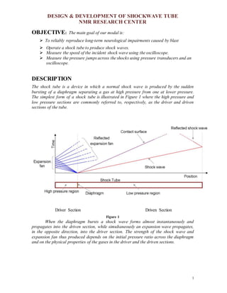
The shock tube is a device in which a normal shock wave is produced by the sudden
bursting of a diaphragm separating a gas at high pressure from one at lower pressure.
The simplest form of a shock tube is illustrated in Figure 1 where the high pressure and
low pressure sections are commonly referred to, respectively, as the driver and driven
sections of the tube.
Driver Section Driven Section
Figure 1
When the diaphragm bursts a shock wave forms almost instantaneously and
propagates into the driven section, while simultaneously an expansion wave propagates,
in the opposite direction, into the driver section. The strength of the shock wave and
expansion fan thus produced depends on the initial pressure ratio across the diaphragm
and on the physical properties of the gases in the driver and the driven sections.
2. DESIGN & DEVELOPMENT OF SHOCKWAVE TUBE
NMR RESEARCH CENTER
2
The Shock Tube Experiment
In this experiment a normal shock wave traveling down a shock tube will be studied. The
shock tube is initially divided into a driver and a driven section by a diaphragm. The
shock wave is created by increasing the pressure in the driver section until the diaphragm
bursts, sending a normal shock wave down the shock tube into the low pressure driven
section and at the same time sending an expansion wave into the high pressure driver
section.
Two quartz pressure transducers are placed along the shock tube to monitor the
normal shock wave as it travels down the tube (Figure 7).The older transducer has
problems with low amplitude pressure pulses. Both transducers are of the quartz
piezoelectric type. These can measure very high-speed fluctuations but are not capable of
measuring DC or constant pressures. The transducers are connected to a digital
oscilloscope. The oscilloscope is used to measure both:
The time it takes for the shock wave to travel between pressure transducer K-1 and
pressure transducer K-2; and
The change in pressure as the normal shock wave passes pressure transducer K-1
and K-2.
Data will be taken for different normal shock waves traveling down the shock tube. The
different normal shock waves will be created by using different diaphragms and different
initial conditions in the driver and driven sections.
Kistler Charge
Amplifiers
Digital Oscilloscope
Kistler Pressure
Transducers
Diaphragm
Driver Section Driven Section
Air-Compressure
Pressure meter
Release valve
Mylar sheet
Schematic Block Diagram of Shockwave Tube