1. @CRC Press 2015. This chapter appears as N. Gekakis, A. Nadeau, M. Hassanalieragh, Y. Chen, Z. Liu, G. Honan, F. Erdem, G.
Sharma and T. Soyata, "Modeling of Supercapacitors as an Energy Buffer for Cyber-Physical Systems," Cyber Physical Systems -
A Computational Perspective, Edited by G. Deka, CRC, 2015.
Modeling of Supercapacitors as an
Energy Buffer for Cyber-Physical
Systems
Nicholas Gekakis, Andrew Nadeau, Moeen Hassanalieragh, Yiyang Chen, Zhaojun Liu,
Grayson Honan, Fatih Erdem, Gaurav Sharma, Tolga Soyata
Dept. of Electrical and Computer Engineering, University of Rochester
ABSTRACT
Supercapacitors have superior power density, 10x higher than that of the rechargeable batteries, while
their energy density (i.e., charge storage capacity) is only one tenth that of comparable size rechargeable
batteries. Despite this low energy density, supercapacitors have been the indispensable components of
high-powered industrial applications, such as elevators, car starters, and brake energy regeneration
systems in hybrid cars. One noticeable commonality in all of these applications is the irrelevance of the
energy loss during the storage and consumption of energy. Since the energy is being stored and consumed
at rates unmanageable by any other energy storage device, the loss of energy is tolerated. In this paper, we
concentrate on a set of embedded systems that utilize supercapacitors for completely different reasons: In
addition to their peak power output capability, supercapacitors also possess superior features such as
environmental-friendliness, long operational lifetime (e.g., a million charge/discharge cycles, as opposed
to a maximum of 5,000 as in the best commercially available rechargeable batteries), and energy-
predictability. Our target embedded systems consume only 1–10 Watts of power, as opposed to the near-
MW levels for the aforementioned industrial applications, and are nearly agnostic to the peak power
capability. While these systems can significantly benefit from these superior features of the
supercapacitors, one feature becomes the most important one: the energy storage and consumption
efficiency. Through MATLAB-based simulations utilizing the existing supercapacitor models, we show
that, at certain power consumption levels, supercapacitors are nearly 100% efficient, while their
efficiency suffers dramatically when they are pushed outside their comfortable operating region. We
demonstrate this using simulations on four different size (and type) supercapacitors and determine these
efficient operation regions for each size supercapacitor.
Keywords:Supercapacitors; Cyber-physical Systems; Energy Buffering; Energy Harvesting;
2. @CRC Press 2015. This chapter appears as N. Gekakis, A. Nadeau, M. Hassanalieragh, Y. Chen, Z. Liu, G. Honan, F. Erdem, G.
Sharma and T. Soyata, "Modeling of Supercapacitors as an Energy Buffer for Cyber-Physical Systems," Cyber Physical Systems -
A Computational Perspective, Edited by G. Deka, CRC, 2015.
INTRODUCTION
Supercapacitors are established as a compelling solution for high power buffering applications due to
their ability to bank and supply power at levels an order of magnitude beyond the capabilities of
electrochemical battery technologies per unit weight. This superior power density has been utilized for
regenerative breaking (Rotenberg, Vahidi, & Kolmanovsky, 2011) elevator (Rufer & Barrade, 2002), and
automating starting systems for combustion engines (Catherino, Burgel, Shi, Rusek, & Zou, 2006).
Additionally, recent developments have also begun using supercapacitors for energy storage applications
in order to take advantage of their excellent charge discharge efficiency as well as their power density
capabilities. Energy efficiency is especially critical for self-sustaining environmentally powered systems,
where efficient storage/use of a limited energy supply can prolong time of operation and improve quality
of service. Another useful characteristic of supercapacitors is their relationship between terminal voltage
and stored energy remaining. This relationship provides more accurate energy awareness for systems with
dynamic supply and usage of power.
However, reliance on these efficiency, power density, and energy awareness benefits for design of
supercapacitor-based systems must be tempered by the fact that supercapacitors do not operate as ideal
devices. Classical concepts of capacitance apply much more closely to parallel plate or electrolytic
devices. Observed supercapacitor behavior differs significantly from theoretical ideal capacitor
performance.
These
operational
differences
between
supercapacitors
and their much
weaker
conventional
cousins are a
direct result of the physical phenomena governing supercapacitor behavior. Dynamic system and
equivalent circuit models have been developed to characterize supercapacitor performance. However,
focus has been on accurately predicting supercapacitor frequency response for power buffering
applications using techniques such as EIS (electrochemical impedance spectroscopy) e.g. (Bertrand,
Sabatier, Briat, & Vinassa, 2010) or characterizing long term storage efficiency for low power
applications (Zhang & Yang, 2011).
An emerging category of application, cyber-physical systems also hold potential to benefit from
supercapacitor energy buffering. Cyber-physical systems have the ability to deploy significant
computational resources into the field at the location the data is collected. For example, these
computational resources can enable face recognition, without the need to transmit high bandwidth video
streams back to a base station. While communication overheard and the need for infrastructure such as the
base stations are reduced for cyber-physical systems, these systems can require much higher power to
sustain their computational capabilities as opposed to wireless sensor nodes. Additionally these systems
are many times remotely deployed, making maintenance costly. Supercapacitors can be an ideal fit for
cyber physical systems due to their long operational lifetimes and peak power capabilities.
Conventional
Capacitors
Supercapacitors
Electrochemical
Batteries
Energy Density �
𝑊∗ℎ
𝑘𝑔
� 10−2
to 10−1
100
to 101
101
to 102
Power Density (
𝑤
𝑘𝑔
) 103
to 104
103
to 104
101
to 102
Efficiency ≥95% ≥95%* 70% to 99%
Table 1. Significant benefits are possible in supercapacitor-based systems.
*efficiency performance can be jeopardized by naive disregard for non-ideal
supercapacitor behavior.
3. @CRC Press 2015. This chapter appears as N. Gekakis, A. Nadeau, M. Hassanalieragh, Y. Chen, Z. Liu, G. Honan, F. Erdem, G.
Sharma and T. Soyata, "Modeling of Supercapacitors as an Energy Buffer for Cyber-Physical Systems," Cyber Physical Systems -
A Computational Perspective, Edited by G. Deka, CRC, 2015.
This chapter begins by introducing an accepted model for supercapacitor behavior and then presents the
analysis of this model relevant to supercapacitors used in energy buffering equations. Specifically, the
analysis describes how the three branch model is implemented to provide energy awareness and track a
system’s remaining available energy. The model is also simulated to characterize energy storage
efficiency trade-offs for supercapacitors. By implementing a simulated supercapacitor model which
describes non-ideal behaviors this paper offers insight into the most significant factors affecting
efficiency and the utility of supercapacitors for energy storage applications. Primary factors influencing
storage efficiency are found to be supercapacitor size, stored energy level, and power at which energy
must be delivered. A three branch equivalent circuit model (Zubieta & Bonert, 2000) based on the
physical phenomena governing supercapacitor behavior is used to simulate these performance trade-offs.
These simulations demonstrate how the exceptional charge-discharge efficiency benefits of
supercapacitor-based storage can be severely degraded depending on power level, supercapacitor voltage,
and supercapacitor size. These implications for energy efficiency must be considered in system design to
realize the benefits of supercapacitor based energy storage over alternatives such as rechargeable
batteries.
Our simulations, implementing the three branch equivalent circuit model for supercapacitor behavior with
parameters both measured from physical devices and taken from literature demonstrate:
1) Superior charge-discharge efficiency for supercapacitor based energy storage.
2) The importance of power-awareness to maintain this superior charge-discharge supercapacitor
performance.
3) The dependence between supercapacitor size and reasonable power level limits on the application
within which near-ideal performance can be expected.
4) The dependence of the near-ideal operation power region limits on supercapacitor terminal
voltage, as well as capacitor size.
The organization of this paper begins by justifying the use of the three branch model as an equivalent
circuit for the physical phenomena that govern supercapacitor operation, explained in the
BACKGROUND AND THREE BRANCH MODEL sections. The next section then details the procedure
for measuring the model’s parameters from a physical supercapacitor device. The KALMAN
FILTERING section then explains how this model can provide an accurate estimate of remaining energy
to the system. The section titled ENERGY EFFICIENCY MODELING lays out the model parameters
and the techniques used to simulate a varied collection of supercapacitors, and explore efficiency
relationships for each. Results showing the significance of design considerations for supercapacitor-based
systems are given in the evaluation section. To conclude, findings are summarized in the
CONCLUSIONS AND FUTURE WORK section.
BACKGROUND
To motivate the significance of efficiency trade-offs inherent in supercapacitor energy storage we first
outline the principles and construction of supercapacitors. Relevant supercapacitor properties include: 1)
orders of magnitude greater energy storage capacity than conventional or electrolytic capacitors, 2)
superior peak power performance in relation to electrochemical batteries, 3) long operational lifetime and
low environmental impact, 4) internal charge redistribution among an array of internal time constants, 5)
ESR (equivalent series resistance), and 6) self discharge leakage current.
4. @CRC Press 2015. This chapter appears as N. Gekakis, A. Nadeau, M. Hassanalieragh, Y. Chen, Z. Liu, G. Honan, F. Erdem, G.
Sharma and T. Soyata, "Modeling of Supercapacitors as an Energy Buffer for Cyber-Physical Systems," Cyber Physical Systems -
A Computational Perspective, Edited by G. Deka, CRC, 2015.
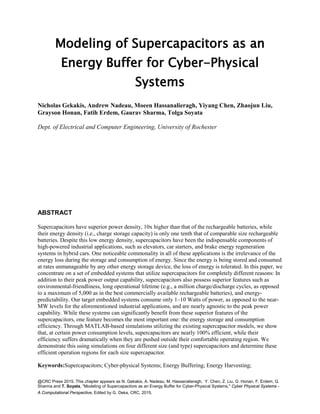
In contrast to conventional capacitors in which
opposing electric charge collects on electrode
plates separated by a dielectric layer,
supercapacitors physical design is shown in
Figure 1. Instead of storing energy through the
electric field created within a dielectric,
supercapacitor electrodes are constructed of
porous material such as activated carbon with
extremely high surface area. Both mechanisms
by which supercapacitors store charge, EDL
(electric double layers) and pseudocapacitance
(Conway, Birss, & Wojtowicz, 1997),
contribute to energy storage proportional to
electrodes' surface area. These phenomena,
linking electrode surface area to capacitance,
explain how such high capacitance is possible
by using activated carbon electrodes with
surface areas in the range of thousands of
square meters per gram. The EDL and
pseudocapacitance mechanisms also account for the relationships between power consumption,
supercapacitor voltage level, and efficiency developed in later in this chapter.
The first charge storage mechanism, EDL, has been used to refer to supercapacitor devices as electric
double layer capacitors and results from the accumulation of opposing charge on the surfaces of the two
electrodes. This surface charge accumulates because the ion permeable membrane prevents the terminal
voltage from driving direct current flow between the two regions of activated carbon electrode material
connected to the opposite terminals. The EDL phenomena occurs because opposing electrode surface
charges on either side of the membrane selectively attract charged ions of the opposite polarity from the
electrolyte. As the electrolyte ions flow through the electrode material pores towards the opposing surface
charges, concentration gradients build up resulting in Helmholtz layers. Helmholtz layers refer to the high
concentrations of oppositely charged ions from the electrolyte that counteract the electrode surface
charges by collecting along the porous electrode material surface. Supercapacitor charge storage by
means of this EDL, relying on diffusion of ions, contrasts electrochemical batteries where re-dox
(reduction oxidation) reactions store charge but limit charge and discharge power according to the speed
of reaction kinetics. This EDL capacitance along the porous electrode material surface and flow of ions
through electrode pores has motivated the use of RC transmission line elements to model the electrical
behavior of the porous electrode supercapacitor design (Bertrand, Sabatier, Briat, & Vinassa, 2010)
(Buller, Karden, Kok, & De Doncker, 2001). These models predict supercapacitor charge redistribution
over a network of RC time constants. Another important effect of the torturous path ions must flow
through to reach the electrode surfaces is significant supercapacitor ESR, resulting in wasted energy
expended to support the ion currents.
Figure 1. Typical supercapacitor construction
includes two electrodes consisting of high surface
area activated carbon immersed in an electrolyte.
Positive and negative terminals of the supercapacitor
are connected to distinct regions of the electrode
material separated by a membrane. This membrane
is only permeable to the electrolyte and allows
charge carrying ions to pass through, but keeps the
regions of electrode material isolated, preventing
current from directly flowing between electrodes
5. @CRC Press 2015. This chapter appears as N. Gekakis, A. Nadeau, M. Hassanalieragh, Y. Chen, Z. Liu, G. Honan, F. Erdem, G.
Sharma and T. Soyata, "Modeling of Supercapacitors as an Energy Buffer for Cyber-Physical Systems," Cyber Physical Systems -
A Computational Perspective, Edited by G. Deka, CRC, 2015.
The second mechanism by which charge is stored in supercapacitors, pseudocapacitance, relies on charge
transfer in re-dox reactions that occur at the electrolyte-electrode surface interface (Conway, Birss, &
Wojtowicz, 1997). However, parasitic side reactions can also spontaneously dissipate stored energy (Niu,
Pell, & Conway, 2006). This energy loss can be modeled as a leakage current and depends on many
factors such as initial charge, storage duration, and temperature (Zhang & Yang, 2011) (Yang & Zhang,
2011). Another source of supercapacitor charge leakage is direct ohmic pathways by which current flows
between terminals through the membrane.
Both significant sources of energy waste which degrade supercapacitor efficiency, ESR and leakage, are
accounted for in the three branch model equivalent circuit (Zubieta & Bonert, 2000), shown inFigure 2.
Supercapacitor charge redistribution is modeled by the three resistive capacitive branches, each with
progressively greater time constant. Supercapacitor ESR is modeled by the series resistors: R1, R2, and R3;
and self discharge leakage is modeled by the parallel resistor Rleak. Using this three branch model, results
show how instantaneous supercapacitor efficiency depends on both application power and supercapacitor
voltage levels. This work builds on our previous study of how net supercapacitor efficiency and effective
capacity vary for charge-discharge profiles of varying speed. Supercapacitor efficiency and capacity have
been shown to depend on the different distributions of charge that result from different charging and
discharging speeds. By using the same measured parameters for the supercapacitor model previously
validated against experimental results, this work uses the three branch model to simulate how
instantaneous supercapacitor efficiency changes with power and voltage level, controlling for charge
redistribution by fixing equal voltage levels across all capacitive branches of the three branch model to
remove the effects of charge redistribution.
EQUAL SERIES RESISTANCE (ESR)
For electrical current to charge or discharge a supercapacitor, ions must diffuse through the electrolyte
into the torturous pathways in the porous electrode material. Any movement of theses ions results in
waste heat just as electrical current flowing through a resistance. In a double layer supercapacitor, the
resistivity of carbon particles within the electrode materials also contribute to the supercapacitor’s
equivalent series resistance (ESR) (Zubieta & Bonert, 2000). The equivalent series resistance plays an
Figure 2. The three branch equivalent circuit supercapacitor model (Zubieta & Bonert, 2000)
accounts for charge redistribution between the immediate, delayed and long term capacitive branches
of increasing time constant. Resistances in the three capacitive branches model internal
supercapacitor ESR while the fourth purely resistive branch models supercapacitor charge leakage.
The initial branch also models voltage dependent capacitance observed for supercapacitors.
6. @CRC Press 2015. This chapter appears as N. Gekakis, A. Nadeau, M. Hassanalieragh, Y. Chen, Z. Liu, G. Honan, F. Erdem, G.
Sharma and T. Soyata, "Modeling of Supercapacitors as an Energy Buffer for Cyber-Physical Systems," Cyber Physical Systems -
A Computational Perspective, Edited by G. Deka, CRC, 2015.
important role in applications where the power density is a major concern (Hassanalieragh, Soyata,
Nadeau, & Sharma, 2014). Examples of such applications are elevators and electric vehicles. In such
cases, a large amount of energy must be supplied in a very short amount of time which in turn leads to a
high current. High current across the series resistance leads to a voltage drop which decreases the energy
delivery efficiency. This problem can be mitigated by having several supercapacitors in parallel.
LEAKAGE AND CHARGE REDISTRIBUTION
High leakage, also known as self-discharge, is the loss of energy stored in a device and is frequently cited
as a major drawback of supercapacitors. It is widely reported that leakage increases exponentially with a
device’s terminal voltage, however research has shown that real leakage is not as significant a problem as
was previously believed and that most of the observed leakage effects are actually due to charge
redistribution within the supercapacitor. This process is illuminated by models of supercacpitors such as
the three branch model. Charge redistribution occurs when a supercapacitor has stopped charging and one
of the capacitors in the model had significantly more charge put into it than the others; it can be thought
of as similar to battery relaxation. This occurs frequently because of the large difference in time constants
of the three branches leads each branch to take in energy at widely different time frames, with the first
branch getting charged up in seconds, while the third branch can take hours. In other words, once
charging stops, the branches with larger time constants, continue to charge, taking their energy from the
branches with lower time constants.
Consequently, it has been shown that the longer a supercapacitor charges for, the slower its
exhibited leakage. The redistribution of charge leads to a reduction in the terminal voltage of the super
capacitor and has therefore been perceived as leakage instead of redistribution. The redistribution is not
without energy loss, however; as the charge redistributes itself, energy is lost in each branch’s resistance.
Energy loss in supercapacitors therefore has two sources: leakage and redistribution loss. Research has
shown that supercapacitors charged for a very short time, for example 0.1 hours, lose the majority of their
energy through redistribution, while supercapacitors charged for a long time, for example 10 hours, lose
the majority of their energy through leakage. Increased energy loss due to leakage in supercapacitors that
have been charged for a long time can be attributed to the fact that they maintain high voltage longer.
Meanwhile the quickly charged supercapacitors redistribute their charge very quickly, thus lowering their
voltage and minimizing leakage. Thus, in situations that require a minimum voltage it should be kept in
mind that the more time a supercapacitor is given to charge, the longer it is able to maintain a high
voltage (Merrett & Weddell, 2012).
Leakage is only relevant in applications that use supercapacitors as long term storage, such as
field systems that need supercapacitors as a long-term energy buffer (Fahad, et al., 2012) (Hassanalieragh,
Soyata, Nadeau, & Sharma, 2014). Alternatively, other usage scenarios are nearly agnostic to leakage. For
example, for data centers running intensive applications (Kocabas & Soyata, 2014) (Kocabas, et al., 2013)
(Kwon, et al., 2014) (Li, Ding, Hu, & Soyata, 2014) (Page, Kocabas, Soyata, Aktas, & Couderc) (Wang,
Liu, & Soyata, 2014) (Soyata, Friedman, & Mulligan, 1995) (Soyata, Ba, Heinzelman, Kwon, & Shi,
2013) (Guo, Ipek, & Soyata, 2010) (Soyata, et al., 2012), supercapacitors are used as a temporary energy
buffer. Each computer on the data center racks could have a peak power demand, which is supplied from
a supercapacitor block. In this case, the energy is stored and buffered within less than a minute, leaving
no time for the leakage to take effect. Typically, the leakage time constant is in the order of hours.
Therefore, any application that uses the stored energy in a supercapacitor (or a block of supercapacitors)
7. @CRC Press 2015. This chapter appears as N. Gekakis, A. Nadeau, M. Hassanalieragh, Y. Chen, Z. Liu, G. Honan, F. Erdem, G.
Sharma and T. Soyata, "Modeling of Supercapacitors as an Energy Buffer for Cyber-Physical Systems," Cyber Physical Systems -
A Computational Perspective, Edited by G. Deka, CRC, 2015.
will not be affected from leakage. Leakage can be thought of as being an Eqauivalent Parallel Resistor
(EPR), connected in parallel, to the three branches.
Three Branch Model
Researchers at the University of Toronto set out to develop a simple model that accurately illustrates a
supercapacitor’s behavior in the first 30 minutes of a charge or discharge cycle. Additionally, they desired
for their model to require only parameters that could be measured at the terminals of the supercapacitor.
An RC circuit is used to best model the behavior of supercapacitors, however more than one, each with a
unique time constant, is necessary due to the different time frames over which supercapacitors respond
(Zubieta & Bonert, 2000). This range in response time is due to the same feature of supercapacitors that
allows them to have such high capacitance: the incredible porousness of the materials they are made form.
This is because the charge has to navigate through the caverns of the material, which result in many
different paths of varying length to be taken. The result is an uneven charging for rapid charge cycles,
which in turn brings about charge redistribution effects. Charge redistribution, it should be noted, is also
responsible for drop in terminal voltage and is part of the reason energy estimation in super capacitors
should not be based off of their terminal voltage (Nadeau, Sharma, & Soyata, 2014).
An arbitrary number of branches can be used for the model however, three has been suggested as it is the
least required to obtain a reasonably accurate model of supercapacitor behavior over a time period of
thirty minutes. Each branch consists of a resistor to model the energy lost in the materials that form the
double layer charge distribution, and a capacitor to model the capacitance between the electrode and
electrolyte. Each branch’s time constants should vary widely, ideally being at least one order of
magnitude apart from each other, so that only the behavior of a single branch is dominating the overall
behavior of the model at any given time. This in turn makes it significantly easier to determine the
parameters of each branch that allows the model to be simpler to use as well as more accurate. The first
branch, the immediate branch, has the smallest time constant and models the immediate response, in the
first seconds, to charging. The second branch, which the authors call the delayed branch, models the bulk
of what occurs in the first minutes of charging. The final branch, the long-term, branch models what
occurs past 10 minutes. The first branch contains an additional, voltage dependent capacitor, in order to
simulate the voltage dependency behavior exhibited by supercapacitors. Out of interest for simplicity, the
other two branches do not contain this additional capacitor. Finally, in addition to the three RC branches
in the model, a parallel resistor is included to simulate leakage and self-discharge effects in the
supercapacitor (Zubieta & Bonert, 2000).
The three branch model is just one of many proposed to model the behavior of supercapacitors, however
it has been shown to be the one to most adequately addresses long term behavior. That being said the
three branch model is not without its drawbacks: it was developed to model larger supercapacitors and
loses some accuracy when applied to smaller ones that might be used in cyber physical systems or
wireless sensor networks. Additionally, it takes each branch to be completely independent, which research
has shown, is not an accurate reflection of supercapacitor behavior. Despite this, the three branch model
remains the most accurate, even for small supercapacitors, due mainly to the fact that the majority of the
research and literature concerns larger supercapacitors and there is not as thorough an understanding of
smaller supercapacitors (Weddell, Merrett, Kazmierski, & Al-Hashimi, 2011).
8. @CRC Press 2015. This chapter appears as N. Gekakis, A. Nadeau, M. Hassanalieragh, Y. Chen, Z. Liu, G. Honan, F. Erdem, G.
Sharma and T. Soyata, "Modeling of Supercapacitors as an Energy Buffer for Cyber-Physical Systems," Cyber Physical Systems -
A Computational Perspective, Edited by G. Deka, CRC, 2015.
MEASURING THE THREE BRANCH MODEL PARAMETERS
In this section we elaborate on measuring the three branch model parameters based on the approach which
was originally introduced in (Zubieta & Bonert, 2000) . A precisely timed and controllable current source
is needed for conducting the experiment in order to be able to keep track of the injected charge. This
method presumes distinct time constant of three branches. Initially the supercapacitor is charged to the
rated voltage in a very short amount of time. The charging period must be short enough to make sure the
initial charge is placed only on the first branch. Observing the terminal voltage in this period leads to
identifying the first branch parameters. After that, the current source is turned off and analyzing the
terminal voltage over a longer period of time will lead to measuring other two branches parameters. The
supercapacitor must be completely discharged prior to conducting the experiment which needs the
supercapacitor to be in short circuit state for a long time.
Throughout this section we refer to 'instantaneous capacitance' many times. The usual definition of
capacitance is actually the relation between supplied charge and the voltage of the capacitor which is =
𝑄
𝑉
. When working with variable capacitance this definition must be revisited: If we inject a small amount of
charge (dQ) into the capacitor , there will be ∆𝑉 voltage change. The instantaneous capacitance at this
specific voltage determines the relation between the injected charge and the voltage difference.
Specifically we have:
𝐶𝑖𝑛𝑠𝑡(𝑉′) =
𝑑𝑄
𝑑𝑉
| 𝑉′ .
A. First Branch Parameter Measurement
If we denote the supercapacitor terminal voltage shortly after turning on the current source by 𝑉1 (taking
into account the rise time of the current source) and the charging current by 𝐼𝑐ℎ we have:
𝑅1 =
𝑉1
𝐼𝑐ℎ
.
We can use the instantaneous capacitance of the supercapacitor during charging to the rated voltage to
determine 𝐶1and 𝐶1𝑉𝑎𝑟 . Instantaneous capacitance (𝐶𝑖𝑛𝑠𝑡)is defined by:
𝐶𝑖𝑛𝑠𝑡 = 𝐼𝑐ℎ
∆𝑡
∆𝑉
.
in which ∆𝑉 is the supercapacitor voltage change during small time period∆𝑡. After finding the
instantaneous capacitance in rated operating voltage range using a high current, we can determine 𝐶1 and
𝐶1𝑉𝑎𝑟 by the use of a simple least square line fitting method.
B. Second Branch Parameter Measurement
After turning off the current source there is an immediate voltage decrease due to 𝑅1. We denote the
terminal voltage by 𝑉1at this time stamp. As in the case of turning on the current source, the fall time of
the current source must also be taken into account. We continue monitoring the terminal voltage
afterwards. The voltage starts decreasing because of charge redistribution. If there is ∆𝑉 voltage change in
9. @CRC Press 2015. This chapter appears as N. Gekakis, A. Nadeau, M. Hassanalieragh, Y. Chen, Z. Liu, G. Honan, F. Erdem, G.
Sharma and T. Soyata, "Modeling of Supercapacitors as an Energy Buffer for Cyber-Physical Systems," Cyber Physical Systems -
A Computational Perspective, Edited by G. Deka, CRC, 2015.
∆𝑡 amount of time we can assume there is a virtually constant current from first to second branch (𝐼𝑡𝑟)
given by:
𝐼𝑡𝑟 =
𝑉1 −
∆𝑉
2
𝑅2
.
∆𝑉 must be small enough so that this holds true. ∆𝑉 is commonly chosen to be 50 mV. Choosing a
smaller voltage difference will lead to better approximation of the constant current, but the precision of
the measurement device (both sampling frequency and voltage measurement precision) prevents us from
choosing a very small voltage difference.
We can relate 𝐼𝑡𝑟to the first branch instantaneous capacitance (𝐶𝑖𝑛𝑠𝑡) which is measured at 𝑉1 − ∆𝑉/2 by
𝐼𝑡𝑟 = 𝐶𝑖𝑛𝑠𝑡 ∗ ∆𝑉/∆𝑡. Using the two derived equations for 𝐼𝑡𝑟 we have:
𝑅2 =
�𝑉1 −
∆𝑉
2
� ∗ ∆𝑡
𝐶𝑖𝑛𝑠𝑡 ∗ ∆𝑉
.
For measuring the second branch capacitance𝐶2, we need to wait long enough so that charge
redistribution from first to second branch has already taken place. Typically the time constant of the
second in a double layer supercapacitor is of order 100 seconds. Waiting for three times the time constant
will be adequate. 𝐶2can be easily calculated by taking into account the charge conservation fact,
specifically we have: 𝑄𝑡𝑜𝑡𝑎𝑙 = 𝑄1 + 𝑄2 , where 𝑄𝑡𝑜𝑡𝑎𝑙 is the total charge supplied to the supercapacitor
and 𝑄1 and 𝑄2 are the amount of charge present in first and second branch respectively.𝑄𝑡𝑜𝑡𝑎𝑙is easily
determined by considering the charging period and the charging current.
If the terminal voltage is 𝑉2 at the end of this period we can write:
𝑄1 = � (𝐶1 + 𝐶1𝑣𝑎𝑟 ∗ 𝑉)𝑑𝑉
𝑉2
0
= 𝑉2 �𝐶1 +
𝐶1𝑣𝑎𝑟
2
∗ 𝑉2�,
𝑄2 = 𝑉2 ∗ 𝐶2 .
So we can easily derive:
𝐶2 =
𝑄𝑡𝑜𝑡𝑎𝑙
𝑉2
− �𝐶1 +
𝐶1𝑣𝑎𝑟
2
∗ 𝑉2�.
C. Third Branch Parameter Measurement
When charge redistribution between first and second branch has taken place, there is still no charge on the
third branch due to its very long time constant.
For determining 𝑅3 , we will wait ∆𝑡 amount of time until the terminal voltage reaches 𝑉3 = 𝑉2 − ∆𝑉
where ∆𝑉 is a small value e.g. 50 mV as it was chosen for calculating 𝑅2. Since ∆𝑉 is pretty small there is
a virtually constant transfer current to the third branch given by: 𝐼𝑡𝑟 = (𝑉2 −
∆𝑉
2
)/𝑅3 while holding the
assumption 𝑅1 ≪ 𝑅2 ≪ 𝑅3. Since time constant of the first branch is quite shorter compared to the
10. @CRC Press 2015. This chapter appears as N. Gekakis, A. Nadeau, M. Hassanalieragh, Y. Chen, Z. Liu, G. Honan, F. Erdem, G.
Sharma and T. Soyata, "Modeling of Supercapacitors as an Energy Buffer for Cyber-Physical Systems," Cyber Physical Systems -
A Computational Perspective, Edited by G. Deka, CRC, 2015.
second branch, 𝐼𝑡𝑟 is mostly supplied by the first branch for this time period. If 𝐶𝑖𝑛𝑠𝑡is the first branch
capacitance at 𝑉2 −
∆𝑉
2
, we can write:
𝑅3 =
�𝑉2 −
∆𝑉
2
� ∗ ∆𝑡
𝐶𝑖𝑛𝑠𝑡 ∗ ∆𝑉
.
For calculating 𝐶3, we have to wait long enough so that the charge redistribution between three branches
has finished. If we assume the terminal voltage is 𝑉4 at the end of this period, we can calculate 𝐶3 by
taking advantage of charge conservation fact:
𝐶3 =
𝑄𝑡𝑜𝑡𝑎𝑙
𝑉4
− �𝐶1 +
𝐶1𝑣𝑎𝑟
2
∗ 𝑉8� − 𝐶2 .
Measurement of the parameters must be conducted on several test units in order to mitigate the possibility
of measurement errors and variation in supercapacitor parameters.
KALMAN FILTERING
The three branch model is used by cyber-physical systems and energy buffering applications to predict a
supercapacitor's behavior. One of the most important aims is to provide a measure of the amount of
energy buffered within a supercapacitor that is available to the system. However, predictions and
measurements that use the three branch model require knowledge of the internal voltages across the
capacitors in the equivalent circuit's three branches. These three branch voltages are referred to as the
supercapacitor's internal state, and cannot be directly observed from a single measurement of the
supercapacitor's terminal voltage. For example, if a supercapacitor is left at rest after is has been charged
up, charge redistribution will cause current to flow to any branch with a lower voltage than the others. All
three branches will settle to an equilibrium at the terminal voltage. In this equilibrium case, the state is
directly observable. However, the same observed terminal voltage could also be produced by rapidly
charging the supercapacitor such that most of the charge is stored in the first branch. Knowledge of the
internal state distinguishes this rapid charging case from the supercapacitor at equilibrium even when the
terminal voltages observed in both cases are identical. Tracking the internal state is important because
while both cases are identical to an observer, the energy buffered in the supercapacitor is significantly
greater for the first case because the long term branches store more energyat equilibrium.
It has been shown that tracking a supercapacitor's internal state provides much greater accuracy than
treating a supercapacitor as an ideal device of capacitance, 𝐶 for which buffered energy, 𝐸 is directly
observable from the terminal voltage, 𝑉𝑠𝑐 as
𝐸 = 1
2� 𝐶𝑉𝑠 𝑐
2
.
Simulations show that this simple observation-only energy awareness scheme underestimates the buffered
energy in a supercapacitor by a root mean square error of 31% over a test profile including charging and
discharging at various current levels (Nadeau, Sharma, & Soyata, 2014).Stored energy is underestimated
because approximating the supercapacitor as an ideal device neglects the long term branches that store
additional energy when the supercapacitor is charged slowly. A supercapacitor's rated capacitance
11. @CRC Press 2015. This chapter appears as N. Gekakis, A. Nadeau, M. Hassanalieragh, Y. Chen, Z. Liu, G. Honan, F. Erdem, G.
Sharma and T. Soyata, "Modeling of Supercapacitors as an Energy Buffer for Cyber-Physical Systems," Cyber Physical Systems -
A Computational Perspective, Edited by G. Deka, CRC, 2015.
normally represents the device's average instantaneous capacitance measured while it is quickly charged.
The ideal model can be adjusted for applications that operate within a narrow power range by increasing
𝐶 in proportion to the extra energy stored on the longer term branches at that specific power level. This
strategy of fitting a supercapacitor with a single constant capacitance value that is dependent on the
operating power fails for applications with variable power supply and demand such as cyber-physical
systems that rely on solar power. Solar power can vary day to day, hour to hour, and even minute to
minute in the case of variable cloud cover, causing varying portions of charge to be stored in the three
branches, depending on how the supercapacitor is charged and discharged.
An alternative to modeling the supercapacitor as simple ideal capacitor is to treat the supercapacitor as a
black box and integrate the net power into and out of the supercapacitor without the need for any
modeling. Buffered energy is found as the difference between the energy inputted, determined by the
current into the supercapacitor over time, 𝐼𝑖𝑛(𝑡) and the energy outputted to the application, determined
by the current out of the supercapacitor over time, 𝐼 𝑜𝑢𝑡(𝑡),
𝐸 = � 𝐼𝑖𝑛(𝑡)𝑉𝑠𝑐(𝑡) 𝑑𝑡 − � 𝐼 𝑜𝑢𝑡(𝑡)𝑉𝑠𝑐(𝑡) 𝑑𝑡 .
Because the above equation does not rely on any model for the supercapacitor it is easily implemented
without the need to set any parameters such as the capacitance, 𝐶. However, neglecting internal loss treats
the supercapacitor as perfect energy storage and overestimates 𝐸 in the long term. In the short term
supercapacitors can operate at an efficiency close to 100% because of their small equivalent series
resistance (Maxwell Technologies, Inc., 2012). However, over the long term leakage and series resistance
losses accumulate and degrade the accuracy of this technique. Additionally the measured quantities
𝐼(𝑡)and 𝑉(𝑡)are always subject to measurement noise. This noise accumulates over time in this model
resulting in significant inaccuracy. For the simulation profile mentioned, this energy awareness scheme is
found to produce a root mean square error of 79.3%, due to the long duration of the simulation which
allows error due to internal losses to accumulate (Nadeau, Sharma, & Soyata, 2014).
As opposed to the two energy awareness schemes described prior, best results are produced by using the
three branch model to determine the energy buffered in a supercapacitor. Assuming that the
supercapacitor's internal state,𝑥 = [𝑉1 𝑉2 𝑉3] 𝑇
is known, the contribution of each branch to the total
buffered energy is calculated as,
𝐸 = 1
2� 𝐶1 𝑉1
2
+ 1
3� 𝐶1𝑣𝑎𝑟 𝑉1
3
+ 1
2� 𝐶2 𝑉2
2
+ 1
2� 𝐶3 𝑉3
2
.
A simple technique to track the state, 𝑥 is to recursively predict 𝑥 each time step according to the
dynamics the equivalent circuit. This method provides acceptable root mean square error of 4.8% in the
simulation because it is only subject to the accumulation of measurement error which is set to be small
and zero mean (Nadeau, Sharma, & Soyata, 2014). However, outside of simulation, modeling error is also
present, and estimates of circuit parameters are imperfect. These inaccuracies introducing systematic error
that accumulates in E over time and would cause greater error in the energy estimate. This prediction-only
method also fails to utilize information in the observed supercapacitor voltage.
12. @CRC Press 2015. This chapter appears as N. Gekakis, A. Nadeau, M. Hassanalieragh, Y. Chen, Z. Liu, G. Honan, F. Erdem, G.
Sharma and T. Soyata, "Modeling of Supercapacitors as an Energy Buffer for Cyber-Physical Systems," Cyber Physical Systems -
A Computational Perspective, Edited by G. Deka, CRC, 2015.
To use both the observed input current into the supercapacitor and the observed terminal voltage to
estimate𝑥 the Kalman filter is used.The discrete Kalman filter provides an optimal estimate of the
supercapacitor’s state, 𝑥� taking into account all observations including the present and previous values of
𝑉𝑠𝑐(𝑡).Given that the three branch equivalent circuit is a linear system of the form,
𝑥̇( 𝑡) = 𝐹 ∙ 𝑥(𝑡) + 𝐵 ∙ 𝐼𝑠𝑐(𝑡) ,
𝑉𝑠𝑐(𝑡) = 𝐻 ∙ 𝑥(𝑡) + 𝐷 ∙ 𝐼𝑠𝑐(𝑡) ,
The prediction for the supercapacitor’s internal state, 𝑥� over any discrete time step can be found by matrix
exponentiation of 𝐹:
𝑥�(𝑡 + ∆𝑡) = 𝑒 𝐹∙∆𝑡
∙ 𝑥�(𝑡) + 𝐹(𝑒 𝐹∙∆𝑡
− 𝐼)𝐵 ∙ 𝐼𝑠𝑐(𝑡) ,
𝑉�𝑠𝑐(𝑡 + ∆𝑡) = 𝐻 ∙ 𝑥�(𝑡 + ∆𝑡) + 𝐷 ∙ 𝐼𝑠𝑐(𝑡 + ∆𝑡) .
The Kalman filter is an efficient iterative solution that uses an update step to incorporate the information
of each new voltage observation into the next estimate of the internal state, 𝑥�(𝑡 + ∆𝑡).Each new
observation is incorporated by distributing the error residual between the predicted terminal voltage and
the actual observation into the predicted state according to the Kalman gain, 𝐾:
𝑥�(𝑡 + ∆𝑡) = 𝑥�(𝑡 + ∆𝑡) + 𝐾 ∙ {𝑉𝑠𝑐(𝑡 + ∆𝑡) − 𝑉�𝑠𝑐(𝑡 + ∆𝑡)} .
The Kalman gain can be calculated analytically for the discrete linear system of the three branch model,
but many times it is approximated using a sigma-point Kalman filter. Alternatively, more complex
models can besimplified by using a linear approximation as in the extended Kalman filter. Of all the
energy awareness techniques mentioned, Kalman filtering provides the lowest root mean squared error at
less than 1% (Nadeau, Sharma, & Soyata, 2014), and is best suited for energy awareness in cyber-
physical systems.
ENERGY EFFICIENCY MODELING
One reason supercapacitors are a good choice for energy buffering, especially in cyber-physical systems,
is that supercapacitors provide high charge-discharge efficiency over a wide range of power levels
without the need for more complex battery management techniques required for electro-chemical
batteries. However, the three branch model includes series resistors and leakage that consume power and
result in less than 100% efficiency. This sections applies the three branch model to determine a power
range that a supercapacitor can comfortably operate within with near 100% efficiency. For example,
cyber-physical systems commonly rely on solar energy harvesting and experience large fluctuations in the
input power. A supercapacitor must efficiently buffer the energy that is harvested regardless of whether
the weather is sunny and provides high power, or the weather is cloudyand energy harvesting is much
slower. The operating efficiency of a supercapacitor is determined by the two sources of internal energy
loss: series resistance in each capacitive branch, and current loss through the parallel resistor in the
leakage branch. At high power, high currents flow in and out of the supercapacitor and make power lost
in the series resistancesa more significant source of loss. At low power losses in the series resistances are
13. @CRC Press 2015. This chapter appears as N. Gekakis, A. Nadeau, M. Hassanalieragh, Y. Chen, Z. Liu, G. Honan, F. Erdem, G.
Sharma and T. Soyata, "Modeling of Supercapacitors as an Energy Buffer for Cyber-Physical Systems," Cyber Physical Systems -
A Computational Perspective, Edited by G. Deka, CRC, 2015.
less significant, but leakage consumes a more significant portion of the power transferred to or from the
supercapacitor.
To test a supercapacitor’s efficiency limits, the three branch model is simulated using various equivalent
circuit parameters. Circuit parameters are measured from an Illinois Capacitor 10F-2.7V-DCNQ (Illinois
Capacitor, Inc., 2012) and Maxwell BCAP0050 (Maxwell Technologies, Inc., 2012), and also simulated
from literature (Zubieta & Bonert, 2000) for the 470F and 1500F DLC (double layer capacitors). These
parameters are listed in Table 2.
Supercapacitor efficiencyis tested over a wide range of power by simulating the three branch model
charged to voltage, 𝑉. Efficiency is then measured by discharging the model through a range of different
load resistances, 𝑅.For each different 𝑅 the supercapacitor’s efficiency, 𝜂 is the ratio between the useful
power delivered to the load, 𝑃 and the total power including the internally wasted power, 𝑃 𝑊 within the
three branch model:
𝜂 =
𝑃
𝑃 + 𝑃𝑤
× 100% .
Depending on a how a supercapacitor is charged, the distribution of charge storage represented in the
three branch model by the voltages across the three capacitances can vary significantly from the terminal
voltage, 𝑉. Simulations remove any ambiguity in the supercapacitor’s internal state by assuming an
equilibrium where the voltage across all capacitors in the three branch model is the same as 𝑉. This
assumption gives intermediate results for efficiency: if the supercapacitor’s internal state is distributed
with more charge stored in the long term branches leakage losses are reduced, but series resistance losses
become worse. If the supercapacitor’s internal state is distributed towards short term storage, series and
leakage losses are skewed in the opposite directions. As the supercapacitor discharges its terminal
voltage, 𝑉𝑠𝑐 is lower than the internal branch voltages, 𝑉. Total wasted power PW across all branches is:
𝑃𝑤 =
(𝑉 − 𝑉𝑠𝑐)2
𝑅1
+
(𝑉 − 𝑉𝑠𝑐)2
𝑅2
+
(𝑉 − 𝑉𝑠𝑐)2
𝑅3
+
𝑉𝑠𝑐
2
𝑅𝑙𝑒𝑎𝑘
,
And power delivered to the load is:
Illinois Capacitor
10F-2.7V-DCNQ
Maxwell BCAP0050
DLC (Zubieta &
Bonert, 2000) 470F
DLC (Zubieta &
Bonert, 2000) 1500F
CRated 10F 50F 470F 1500F
C1 2.05F 42.5F 270F 900F
C1var 6.03𝐹 𝑉⁄ 5.1 𝐹 𝑉⁄ 190 𝐹 𝑉⁄ 600 𝐹 𝑉⁄
R1 56mΩ 205mΩ 2.5mΩ 1.5mΩ
C2 9.43F 10.5F 100F 200F
R2 4.0Ω 112Ω .9Ω .4Ω
C3 6.76F 4F 220F 330F
R3 77.5Ω 628Ω 5.2Ω 3.2Ω
Rleak 90kΩ 36kΩ 9kΩ 4kΩ
Table 2: Three branch model parameters found for 10F Illinois Capacitor and 50F Maxwell
supercapacitor. Parameters for 470F DLC and 1500F DLC supercapacitor from (Zubieta &
Bonert, 2000) also used to test efficiency.
14. @CRC Press 2015. This chapter appears as N. Gekakis, A. Nadeau, M. Hassanalieragh, Y. Chen, Z. Liu, G. Honan, F. Erdem, G.
Sharma and T. Soyata, "Modeling of Supercapacitors as an Energy Buffer for Cyber-Physical Systems," Cyber Physical Systems -
A Computational Perspective, Edited by G. Deka, CRC, 2015.
𝑃 =
𝑉𝑠𝑐
2
𝑅
.
The terminal voltage, 𝑉𝑆𝐶 is determined by solving the node equation for the currents in all of the model’s
branches in addition to current to the load,
𝑉 − 𝑉𝑠𝑐
𝑅1
+
𝑉 − 𝑉𝑠𝑐
𝑅2
+
𝑉 − 𝑉𝑠𝑐
𝑅3
−
𝑉𝑠𝑐
𝑅𝑙𝑒𝑎𝑘
=
𝑉𝑠𝑐
𝑅
.
EVALUATION
Energy buffering efficiency, η for the 10F, 50F, 470F, and 1500F supercapacitors is evaluated using the
equations given in the previous section and shown in Figure 3,Figure 4, Figure 5 and Figure 6. Each
figure plots percent efficiency in relation to power delivered to the load as resistance value, 𝑅 for the load
varies. For example, a large load resistance is used to test supercapacitor efficiency at low power. The
large load resistance prevents the flow of high current and limits the power delivered to the load. As load
resistance is decreased, more current is drawn from the supercapacitor and power increases as 𝑃 = 𝐼𝑠𝑐
2
𝑅.
For each sequence of load resistances there is an inflection point of maximum power that can be drawn
from the supercapacitor. Beyond this maximum power, further decreasing the load resistance no longer
delivers greater power.This inflection point happens because such small 𝑅 draws very high current from
the supercapacitors, and a large amount of wasted power is consumed by the supercapacitors’ ESR. The
efficiency of this maximum power operating point is below the range of efficiencies shown in Figure 3,
Figure 4, Figure 5, and Figure 6. Due to the low efficiency of drawing maximum power and because the
simulated current significantly exceeds the maximum rating of physical devices, these casesdo not occur
in typical energy aware operation.
15. @CRC Press 2015. This chapter appears as N. Gekakis, A. Nadeau, M. Hassanalieragh, Y. Chen, Z. Liu, G. Honan, F. Erdem, G.
Sharma and T. Soyata, "Modeling of Supercapacitors as an Energy Buffer for Cyber-Physical Systems," Cyber Physical Systems -
A Computational Perspective, Edited by G. Deka, CRC, 2015.
As power delivered to the load
increases, efficiency initially
increases due to diminishing
leakage: a greater portion of
the power flows to the load
rather than to the parallel
leakage branch in three branch
model. As in Table 2, leakage
resistance is shown to be
inversely proportional to
supercapacitor size resulting
in more severe inefficiency for
larger supercapacitors at low
power. Inefficiency due to
leakage is also influenced by
the voltage of the
supercapacitor. Because leakage is modeled as current through a resistor, the waste power is 𝑉𝑠𝑐
2
𝑅𝑙𝑒𝑎𝑘⁄ .
Consequently, leakage waste increases with the square of voltage.
The second important relationship between efficiency and power is the inefficiency of supercapacitors
while delivering high power to load resistances. Inefficiency at high power results from high current
flowing through the ESR of the supercapacitor. Consequently as current increases to deliver more power
at a certain voltage or to maintain power at a lower V efficiency suffers. It can be seen that larger
supercapacitors perform better at high power due to their smaller internal ESR, represented by the R1
parameter in the three branch model.
Figure 4. Predicted efficiency for discharging a 10F supercapacitor
is modeled by the three branch model.
10
-6
10
-5
10
-4
10
-3
10
-2
10
-1
10
0
10
1
10
2
10
3
10
4
60
65
70
75
80
85
90
95
100
Power (Watts)Efficiency%
V=2.7V
V=2.0V
V=1.5V
V=1.0V
V=0.5V
Figure 3. Predicted efficiency for discharging a 50F supercapacitor is
modeled by the three branch model. Note that large R1 was measured,
resulting in inefficiency at high power.
10
-6
10
-5
10
-4
10
-3
10
-2
10
-1
10
0
10
1
10
2
10
3
10
4
60
65
70
75
80
85
90
95
100
Power (Watts)
Efficiency%
V=2.7V
V=2.0V
V=1.5V
V=1.0V
V=0.5V
16. @CRC Press 2015. This chapter appears as N. Gekakis, A. Nadeau, M. Hassanalieragh, Y. Chen, Z. Liu, G. Honan, F. Erdem, G.
Sharma and T. Soyata, "Modeling of Supercapacitors as an Energy Buffer for Cyber-Physical Systems," Cyber Physical Systems -
A Computational Perspective, Edited by G. Deka, CRC, 2015.
CONCLUSIONS AND
FUTURE WORK
This paper demonstrated
design considerations that
can jeopardize the charge-
discharge energy efficiency
benefits of supercapacitors
over electrochemical
batteries. Demonstrations
use a three branch model
equivalent circuit with
parameters taken from
previous measurements of
two different physical
devices and two
supercapacitor modeled in literature to give a wide range of capacitances from various manufacturers.
Results show the importance of limiting supercapacitor operation to within suitable power limits. These
power limits for comfortable operation are found to be dependent on both supercapacitor size and voltage
level.
In this paper, a method for measuring the already proposed three branch model is elaborated on. A
precisely timed controlled current source which is capable of supplying large amount of current is needed
for conducting the experiment.
Three branch model is able to characterize supercapacitor behavior over a wide operating range power.
For specific applications, a simplified model could be used where some of the parameters play an
important role. For example, in elevators where there is a need to supply a large amount of energy in a
very short time, series resistance of the first branch plays an important role. In field systems, the field
processor needs to have an estimate of the remaining energy based on supercapacitor voltage. The
dynamics in incoming and outgoing power to super capacitor is limited in such systems, thus the charge
redistribution between
branches may be neglected.
In wireless sensor networks,
supercapacitors are mainly
used as the energy buffer for
an extended period of time.
Thus the leakage resistor is
mostly emphasized.
Operation at both low and
high power outside these
limits result in severely
degraded supercapacitor
efficiency. For example,
while a 1500F capacitor
fully charged to 2.7V may be
Figure 6. Predicted efficiency for discharging a 470F supercapacitor
is modeled by the three branch model.
10
-6
10
-5
10
-4
10
-3
10
-2
10
-1
10
0
10
1
10
2
10
3
10
4
60
65
70
75
80
85
90
95
100
Power (Watts)
Efficiency%
V=2.7V
V=2.0V
V=1.5V
V=1.0V
V=0.5V
Figure 5. Predicted efficiency for discharging a 1500F supercapacitor
is modeled by the three branch model.
10
-6
10
-5
10
-4
10
-3
10
-2
10
-1
10
0
10
1
10
2
10
3
10
4
60
65
70
75
80
85
90
95
100
Power (Watts)
Efficiency%
V=2.7V
V=2.0V
V=1.5V
V=1.0V
V=0.5V
17. @CRC Press 2015. This chapter appears as N. Gekakis, A. Nadeau, M. Hassanalieragh, Y. Chen, Z. Liu, G. Honan, F. Erdem, G.
Sharma and T. Soyata, "Modeling of Supercapacitors as an Energy Buffer for Cyber-Physical Systems," Cyber Physical Systems -
A Computational Perspective, Edited by G. Deka, CRC, 2015.
able to comfortably supply power at 10W at near 100% efficiency, the efficiency of 50F capacitor
discharging at that power level will be below 50%. Furthermore, once the voltage of the 1500F capacitor
falls below 0.5V, it will also suffer from increasing energy waste as efficiency at 10 W will fall to 93%.
In addition to using the three branch model to measure the efficiency of supercapacitors, the three branch
model is also used in a Kalman filtering implementation to accurately track and predict a supercapacitor’s
behavior. Kalman filtering is shown to have greater energy awareness accuracy than simpler methods,
because Kalman filtering is able to optimally update a running prediction of the internal state of a
supercapacitor. Tracking the internal state of a supercapacitor is important because the distribution of
charge in the three branches of the supercapacitor model can significantly impact stored energy, but
cannot be observed from the terminal voltage. While alternative energy awareness methods suffer from
root mean square error ranging from 80% down to 5%, the Kalman filter implementation of the three
branch model has error of less than 1%.
ACKNOWLEDGEMENT
This work was funded in part by the National Science Foundation grant CNS-1239423 and a gift from
Nvidia Corporation.
18. @CRC Press 2015. This chapter appears as N. Gekakis, A. Nadeau, M. Hassanalieragh, Y. Chen, Z. Liu, G. Honan, F. Erdem, G.
Sharma and T. Soyata, "Modeling of Supercapacitors as an Energy Buffer for Cyber-Physical Systems," Cyber Physical Systems -
A Computational Perspective, Edited by G. Deka, CRC, 2015.
REFERENCES
Bertrand, N., Sabatier, J., Briat, O., & Vinassa, J. M. (2010). Embedded fractional nonlinear supercapcitor
model and its parametric estimation method. IEEE Transactions on Industrial Electronics, 3991-
4000.
Buller, S., Karden, E., Kok, D., & De Doncker, R. (2001). Modeling the dynamic behavior of
supercapacitors using impedance spectroscopy. Industry Applications Conference 2001. Thirty-
Sixth IAS Annual Meeting. Conference Record of the 2001 IEEE, 2500-2504.
Catherino, H. A., Burgel, J. F., Shi, P. L., Rusek, A., & Zou, X. (2006). Hybrid power supplies: A
capacitor-assisted battery. Journal of Power Sources, 965-970.
Conway, B., Birss, V., & Wojtowicz, J. (1997). The role and utilization of peudocapacitance for energy
storage by supercapacitors. Journal of Power Sources, 1-14.
Fahad, A., Soyata, T., Wang, T., Sharma, G., Henzelman, W., & Shen, K. (2012). SOLARCAP: Super
Capacitor Buffering of Solar Energy for Self-Sustainable Field Systems. Proceedings of the 25th
IEEE International System-On-Chip Conference (pp. 236-241). Niagra Falls: IEEE.
Guo, X., Ipek, E., & Soyata, T. (2010). Resistive Computation: Avoiding the Power Wall with Low-
Leakage, {STT-MRAM} Based Computing. Proceedings of the International Symposium on
Computer Architecture (ISCA), (pp. 371-382). Saint-Malo, France.
Hassanalieragh, M., Soyata, T., Nadeau, A., & Sharma, G. (2014). Solar-Supercapacitor Harvesting
System Design for Energy-Aware Applications. Proceedings of the 27th IEEE International
System-On-Chip Conference. Las Vegas: IEEE.
Illinois Capacitor, Inc. (2012). Super Capacitor Products. Retrieved 2012, from Illinois Capacitor Inc.
Web site: http://www.illinoiscapacitor.com/ic_search/_super_products.aspx
Kocabas, O., & Soyata, T. (2014). Medical Data Analytics in the Cloud Using Homomorphic Encryption.
In P. Chelliah, & G. Deka, Handbook of Research on Cloud Infrastructures for Big Data
Analytics (pp. 471-488). IGI Global.
Kocabas, O., Soyata, T., Couderc, J.-P., Aktas, M., Xia, J., & Huang, M. (2013). Assessment of Cloud-
based Health Monitoring using Homomorphic Encryption. Proceedings of the 31st IEEE
International Conference on Computer Design (ICCD), (pp. 443-446). Ashville, VA, USA.
Kwon, M., Dou, Z., Heinzelman, W., Soyata, T., Ba, H., & Shi, J. (2014). Use of Network Latency
Profiling and Redundancy for Cloud Server Selection. Proceedings of the 7th IEEE International
Conference on Cloud Computing (IEEE CLOUD 2014), (pp. 826-832). Alaska.
doi:10.1109/CLOUD.2014.114
Li, P., Ding, C., Hu, X., & Soyata, T. (2014). LDetector: A Low Overhead Race Detector for GPU
Programs. 5th Workshop on Determinism and Correctness in Parallel Programming
(WODET2014).
19. @CRC Press 2015. This chapter appears as N. Gekakis, A. Nadeau, M. Hassanalieragh, Y. Chen, Z. Liu, G. Honan, F. Erdem, G.
Sharma and T. Soyata, "Modeling of Supercapacitors as an Energy Buffer for Cyber-Physical Systems," Cyber Physical Systems -
A Computational Perspective, Edited by G. Deka, CRC, 2015.
Maxwell Technologies, Inc. (2012). Maxwell Technologies K2 Series Ultracapacitors High Capacity
Cells. Retrieved 2012, from Maxwell Technologies, Inc. Web site:
http://www.maxwell.com/products/ultracapacitors/products/k2-series
Merrett, G. V., & Weddell, A. S. (2012). Supercapacitor Leakage in Energy-Harvesting Sensor Nodes:
Fact or Fiction? 2012 Ninth International Conference on Networked Sensing Systems (pp. 1-5).
Antwerp: IEEE.
Nadeau, A., Sharma, G., & Soyata, T. (2014). State-of-Charge Estimation for Supercapacitors: A Kalman
Filtering Formulation. Proceedings of the 2014 IEEE International Conference on Acoustics,
Speech, and Signal Processing (pp. 2213-2217). Florence: IEEE.
Niu, J., Pell, W. G., & Conway, B. E. (2006). Requirements for performance characterization of c double-
layer supercapacitors: Applications to a high specific-area c-cloth material. Journal of Power
Sources, 725-740.
Page, A., Kocabas, O., Soyata, T., Aktas, M., & Couderc, J.-P. (n.d.). Cloud-Based Privacy-Preserving
Remote ECG Monitoring and Surveillanc. Annals of Noninvasive Electrocardiology (ANEC).
Rotenberg, D., Vahidi, A., & Kolmanovsky, I. (2011). Ultracapacitor assisted powertrains: Modeling,
control, sizing, and the impact on fuel economy. IEEE Transactions on Control Systems
Technology, 576-589.
Rufer, A., & Barrade, P. (2002). A supercapacitor-based energy storage system for elevators with soft
commutated interface. IEEE Transactions on Industry Applications, 1151-1159.
Soyata, T., Ba, H., Heinzelman, W., Kwon, M., & Shi, J. (2013). Accelerating Mobile Cloud Computing:
A Survey. In H. T. Kantarci (Ed.), Communication Infrastructures for Cloud Computing (pp.
175-197). Hershey, PA, USA: IGI Global. doi:10.4018/978-1-4666-4522-6.ch008
Soyata, T., Friedman, E. G., & Mulligan, J. H. (1995). Monotonicity constraints on path delays for
efficient retiming with localized clock skew and variable register delay. Proceedings of the
International Symposium on Circuits and Systems (ISCAS), (pp. 1748-1751). Seattle, WA.
Soyata, T., Muraleedharan, R., Ames, S., Langdon, J., Funai, C., Kwon, M., & Heinzelman, W. (2012).
COMBAT: mobile-Cloud-based cOmpute/coMmunications infrastructure for BATtlefield
applications. Proceedings of SPIE, (pp. 84030K-13). Baltimore, MD.
Wang, H., Liu, W., & Soyata, T. (2014). Accessing Big Data in the Cloud Using Mobile Devices. In P.
Chelliah, & G. Deka, Handbook of Research on Cloud Infrastructures for Big Data Analytics (pp.
444-470). IGI Global.
Weddell, A. S., Merrett, G. V., Kazmierski, T. J., & Al-Hashimi, B. M. (2011). Accurate Supercapacitor
Modeling for Energy Harvesting Wireless Sensor Nodes. IEEE Transactions on Circuits And
Systems II: Express Briefs, 911-915.
Yang, H., & Zhang, Y. (2011). Self-discharge analysis and characterization of supercapcitors for
enviornmentally powered wireless sensor network applications. Journal of Power Sources, 8866-
8873.
20. @CRC Press 2015. This chapter appears as N. Gekakis, A. Nadeau, M. Hassanalieragh, Y. Chen, Z. Liu, G. Honan, F. Erdem, G.
Sharma and T. Soyata, "Modeling of Supercapacitors as an Energy Buffer for Cyber-Physical Systems," Cyber Physical Systems -
A Computational Perspective, Edited by G. Deka, CRC, 2015.
Zhang, Y., & Yang, H. (2011). Modeling and characterization of supercapacitors for wireless sensor
network applications. Journal of Power Sources, 4128-4135.
Zubieta, L., & Bonert, R. (2000). Characterization of double-layer capacitors for power electronics. IEEE
Transactions on Industry Applications, 199-205.
KEY TERMS AND DEFINITIONS
Supercapacitor: A device used to store electrical energy through two processes: Double Layer
Capacitance and Pseudocapacitance. They are made of highly porous materials such as activated
carbon which allows them to achieve capacitance, energy density, and power density levels
orders of magnitude higher than electrolytic capacitors. Compared to rechargeable batteries,
supercapacitors have much lower energy density but much higher power density. Also known as
Ultracapacitors and Electric Double-Layer Capacitors (ELDCs).
Rechargeable Battery: A type battery whose charge can be replenished by applying a charge in
the reverse (charging) direction. This is the opposite direction from when the stored energy is
being consumed.
Energy Density: The amount of energy stored per unit volume for a given energy buffering
device (e.g., supercapacitor or rechargeable battery). Supercapacitors are known to have around
10 times lower energy density than rechargeable batteries. For example, while supercapacitors
have an average 10 Wh/kg (Watt-hours per kilogram) energy density, a rechargeable battery
typically has a 100 Wh/kg density.
Power Density: The amount of power that can be supplied to the load. Supercapacitors are
known to have around 10 to 100 times better power density than rechargeable batteries.
Primarily determined by their ESR, supercapacitors can supply a real high peak power to the
load. This allows supercapacitors to be used in applications with very high power demand, such
as hybrid electric cars and elevators. It is measured in W/kg (Watts per kilogram).
Pseudocapacitance: Electrochemical storage of energy in supercapacitors by means of redox
reactions. Like, Double Layer Capacitance, it increases with the surface area of the electrode. It
is one of two contributing factors to the overall capacitance of a supercapacitor.
Double Layer Capacitance: Capacitance at the interface of the electrode and electrolyte inside
a supercapacitor. Due to the extremely high surface area of the materials used for electrodes in
supercapacitors, Double Layer Capacitance can be very large. It is one of two contributing
factors to the overall capacitance of a supercapacitor.
Leakage: Energy lost internally in the supercapacitor; increases exponentially with terminal voltage.
Leakage is considered to be high in supercapacitors and is sometimes referred to as self-discharge.
21. @CRC Press 2015. This chapter appears as N. Gekakis, A. Nadeau, M. Hassanalieragh, Y. Chen, Z. Liu, G. Honan, F. Erdem, G.
Sharma and T. Soyata, "Modeling of Supercapacitors as an Energy Buffer for Cyber-Physical Systems," Cyber Physical Systems -
A Computational Perspective, Edited by G. Deka, CRC, 2015.
Charge Redistribution: The evening out of charge across the supercapacitor that occurs most
dramatically when a supercapacitor has been charged over a short period of time. Charge
Redistribution leads to a reduction in terminal voltage, which is sometimes mistaken for voltage.
Three Branch Model: The most accurate model for supercapacitors that consists of three
branches, each containing a resistor and a capacitor. The time constant in each branch is
significantly different from that of the other branches so that only one branch dominates the
supercapacitor behavior at any one time. The three branch model also consists of a parallel
resistor to simulate leakage and a voltage dependent capacitor in the first branch to replicate
supercapacitors’ voltage dependent behavior.
State of Charge: The level of charge of each branch in the three branch model. There is no way
to directly observe state of charge for each of the three branches.
Equivalent Parallel Resistance (EPR): The three branch model approximates the
supercapacitor behavior as three parallel-connected RC pairs. The leakage aspect of
supercapacitors is modeled as a resistor that is connected to these three branches in parallel,
thereby continuously wasting energy. For this reason, the leakage resistor can be thought of as
being an Equivalent Parallel Resistor (EPR).
Equivalent Series Resistance (ESR): The first branch of the three branch model has a very
small resistor connecting to the main capacitor that is the dominant storage element in the entire
supercapacitor. The resistance of this first branch is termed Equivalent Series Resistor (ESR) and
limits the amount of current that can flow from the main terminals into this first branch
capacitor. ESR is an important parameter in determining the power density of the supercapacitor.
Kalman Filter Formulation: A technique used to continuously track the state of charge of the
capacitors in the three branch model. It utilizes recursive operations to continuously estimate the
state of charge. This technique yields accuracy within 1%.
Observable Variables: These are the variables that can be measured and fed back into the
Kalman filter. In the case of supercapacitor modeling, the only two observable variables are the
terminal voltage of the supercapacitor and the terminal current (i.e., the current that is being fed
into the supercapacitor).
Latent Variables: In the Kalman filtering, the latent variables are the ones that the model tries
to estimate, since they cannot be directly measured. In the case of supercapacitor modeling using
Kalman filtering, the latent variables are the individual voltages and currents of the three
branches. When the voltages of three individual branches deviate, they have to eventually
equalize in the long term. So, the primary advantage of using Kalman filtering is to estimate the
latent variables during the iterative Kalman filtering process.
DC-DC Converter: A switching converter that takes energy from a power source and transfers
it to another power source. Specifically, since both of these sources might have different DC
voltage levels, the configuration of the DC-DC converter might have to be chosen specifically
depending on the input/output voltage levels (i.e., Vin vs. Vout). A Boost converter transfer
22. @CRC Press 2015. This chapter appears as N. Gekakis, A. Nadeau, M. Hassanalieragh, Y. Chen, Z. Liu, G. Honan, F. Erdem, G.
Sharma and T. Soyata, "Modeling of Supercapacitors as an Energy Buffer for Cyber-Physical Systems," Cyber Physical Systems -
A Computational Perspective, Edited by G. Deka, CRC, 2015.
energy in the Vout > Vin case, whereas a Buck converter transfers energy in the opposite
scenario (i.e., Vout < Vin). A SEPIC converter can transfer energy in both cases.
Energy Efficiency: Quantifies what percentage of the energy that is input into a DC-DC
converter actually transferred to the output. For example, if 1 Watt is being applied to the input
and a constant 0.85 Watt is being transferred to the output (e.g., to the supercapacitor storage),
this system has an 85% efficiency. In other words, 15% of the incoming energy is wasted.