Quick Installation Guide EGS5110AP
•
0 likes•284 views

1) The document provides instructions for installing and setting up an EnGenius switch, including unpacking the package contents, requirements for where to place the switch, and steps for connecting devices to the switch and accessing the web-based interface. 2) It can be installed on a flat surface or rack using the included mounting brackets, and connected devices include PoE devices like IP cameras. 3) The setup steps include connecting the switch to power, connecting a computer via Ethernet, accessing the web interface using the default IP and logging in, then being able to perform switch configuration and monitoring.

Recommended
Recommended
More Related Content
What's hot
What's hot (11)
Viewers also liked
Viewers also liked (18)
Similar to Quick Installation Guide EGS5110AP
Similar to Quick Installation Guide EGS5110AP (20)
More from EnGenius Europe
More from EnGenius Europe (20)
Recently uploaded
Recently uploaded (20)
Quick Installation Guide EGS5110AP
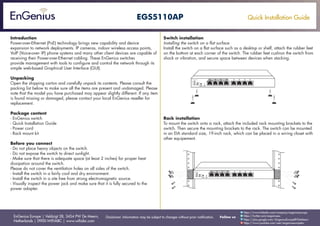
- 1. Quick Installation Guide EnGenius Europe | Veldzigt 28, 3454 PW De Meern, Netherlands | 0900-WIFIABC | www.wifiabc.com Disclaimer: Information may be subject to changes without prior notification. Follow us https://www.linkedin.com/company/engeniuseurope https://plus.google.com/+EngeniusEuropeBVDeMeern https://www.youtube.com/user/engeniuseuropebv https://twitter.com/engeniuseu EGS5110AP Introduction Power-over-Ethernet (PoE) technology brings new capability and device expansion to network deployments. IP cameras, indoor wireless access points, VoIP (Voice-over- IP) phone systems and many other client devices are capable of receiving their Power-over-Ethernet cabling. These EnGenius switches provide management with tools to configure and control the network through its simple web-based Graphical User Interface (GUI). Unpacking Open the shipping carton and carefully unpack its contents. Please consult the packing list below to make sure all the items are present and undamaged. Please note that the model you have purchased may appear slightly different. If any item is found missing or damaged, please contact your local EnGenius reseller for replacement. Package content - EnGenius switch - Quick Installation Guide - Power cord - Rack mount kit Before you connect - Do not place heavy objects on the switch. - Do not expose the switch to direct sunlight. - Make sure that there is adequate space (at least 2 inches) for proper heat dissipation around the switch. Please do not cover the ventilation holes on all sides of the switch. - Install the switch in a fairly cool and dry environment. - Install the switch in a site free from strong electromagnetic source. - Visually inspect the power jack and make sure that it is fully secured to the power adapter. Switch installation Installing the switch on a flat surface Install the switch on a flat surface such as a desktop or shelf, attach the rubber feet on the bottom at each corner of the switch. The rubber feet cushion the switch from shock or vibration, and secure space between devices when stacking. Rack installation To mount the switch onto a rack, attach the included rack mounting brackets to the switch. Then secure the mounting brackets to the rack. The switch can be mounted in an EIA standard size, 19-inch rack, which can be placed in a wiring closet with other equipement.
- 2. Quick Installation Guide EnGenius Europe | Veldzigt 28, 3454 PW De Meern, Netherlands | 0900-WIFIABC | www.wifiabc.com Disclaimer: Information may be subject to changes without prior notification. Follow us https://www.linkedin.com/company/engeniuseurope https://plus.google.com/+EngeniusEuropeBVDeMeern https://www.youtube.com/user/engeniuseuropebv https://twitter.com/engeniuseu EGS5110AP Connecting the switch Connecting the devices to the switch and managing the switch using a web browser Step 1: Connect the supplied power cord to the switch and plug the other end into an electrical outlet. Verify the Power LED indicator is lit on the switch. Step 2: Wait for the switch to complete boot up. It might take few minutes for the switch to completeboot up. Step 3: Connect one end of a Category 5/6 Ethernet cable into the Gigabit (10/100/1000) Ethernet port on the switch’s front panel and the other end to Ethernet port on the computer. Verify that the LED on Ethernet ports of the switch are green. Step 4: Once your computer is on, ensure that your TCP/IP is set to ‘On’ or ‘Enabled’. Open ‘Network Connections’ and then click ‘Local Area Connection’. Select ‘Internet Protocol Version 4 (TCP/IPv4)’. Step 5: If your computer is already on a network, ensure that you have set it to a Static IP Adress on the interface. (Example: 192.168.0.10 and the subnet mask address as 255.255.255.0) Step 6: Open a web browser on your computer. In the address bar of the web browser, enter 192.168.0.239 and enter. Step 7: A login screen will appear. By default, username is admin and the password is password. Enter the current username and password of the switch and then click Login. Step 8: The switch’s web-based Graphical User Interface (GUI) page screen will appear. Use it to perform switch configuration and monitoring.
- 3. Quick Installation Guide EnGenius Europe | Veldzigt 28, 3454 PW De Meern, Netherlands | 0900-WIFIABC | www.wifiabc.com Disclaimer: Information may be subject to changes without prior notification. Follow us https://www.linkedin.com/company/engeniuseurope https://plus.google.com/+EngeniusEuropeBVDeMeern https://www.youtube.com/user/engeniuseuropebv https://twitter.com/engeniuseu EGS5110AP Note: Maximum data rates are based on IEEE802.3an standards. Actual throughput and range may vary depending on distance between devices or traffic and bandwidth load in the network. Features and specifications subject to change without notice. Trademarks and registered trademarks are the property of their respective owners. Copyright ©2013 EnGenius Europe, Inc. All rights reserved. Compliant with FCC - This equipment has been tested and found to comply with the limits for a Class A digital device, pursuant to Part 15 of the FCC Rules. These limits are designed to provide reasonable protection against harmful interference in a residential installation. This equipment generates, uses, and can radiate radio frequency energy and, if not installed and used in accordance with the instructions, may cause harmful interference to radio communications. Operation of this equipment in a residential area is likely to cause harmful interference in which case the user will be required to correct the interference at his own expense.