SlideShare a Scribd company logo
1 of 20
Download to read offline
Linear Stage Systems 
Nippon Pulse America, Inc. 
A subsidiary of Nippon Pulse Motor Co., Ltd. 
Sold & Serviced By: 
ELECTROMATE 
Toll Free Phone (877) SERVO98 
Toll Free Fax (877) SERV099 
www.electromate.com 
sales@electromate.com
Linear Stages SLP 
Nanopositioning Series 
High Precision Linear-Single Axis Stage 
The SCR Nanopositioning Series offers the accuracy of piezo 
driven stages with the speed and performance of servo stages. Through 
complex motion profiles, the SCR series produces extremely accurate 
results with no loss in stability. As in all Linear Shaft Motor applica-tions, 
a non-critical air gap produces an environment that is void of 
any variations in force. 
The SCR stage also includes an integrated cross-roller guide. With 
a simple, lightweight, compact shaft-type linear motor comprised of 
only a magnet and a coil, large drive force is gained with an efficient 
and short coil length, allowing for high speed and high precision appli-cations. 
Because there is no friction, there is no sound or dust, making 
• Moving Stage 
NPM 
• Cross-Roller Guide 
Four SCR stage models allow for design flexibility in high-precision applications 
• Forcer 
High Performance Linear-Single Axis Stage 
There are three SLP models to meet 
your high-performance needs 
• Slider 
• Coil Unit 
• Linear Guide 
N i p p o n www.nipponpulse.com P u l s e A m e r i c a , I n c . 
• Shaft 
• Linear Encoder 
SCR 
AcculinE Series 
the motor maintenance-free. 
SLP15 SLP25 SLP35 
• Shaft 
SCR050 SCR075 SCR100 SCR150 
A high-precision stage for industrial applications, the SLP Ac-culine 
Series stages offer superior technology that is unmatched in 
the industry. 
As an all-inclusive stage, the SLP stage provides integrated 
shaft support within the housing and simplifies the transition from 
conventional ball-screw systems. Because this stage system features 
a lightweight, compact linear shaft drive, the SLP is a low-profile, 
high-precision product. The built-in shaft motor is a maintenance 
free device and also eliminates sound and dust production. 
The SLP series features the smallest deadzone of any similar stage 
system available on the market today. In addition, there are no stages 
on the current market that match the SLP series' force-to-volume 
ratio, making it an outstanding solution for those with space limita-tions. 
Sold & Serviced By: 
ELECTROMATE 
Toll Free Phone (877) SERVO98 
Toll Free Fax (877) SERV099 
www.electromate.com 
sales@electromate.com
www.nipponpulse.Linear Stages 
SCR Stages 
SCR-050 
79 
(3.110) 
A 
B 
28 
(1.102) 
29 
(1.142) 
56 
(2.205) 
12.9 
(0.508) 
14.5 
(0.571) 
M4 Thread 
75.10 
(2.957) 
29.51 (1.162) 
M4 Thru-hole 56 
(2.205) 
29 
(1.142) 
26.4 
(1.039) 
Stage Specifications Units SCR050-020 SCR050-040 
Travel / Stroke mm 20 40 
Length mm 75 95 
Accuracy μm 2 2 
Encoder Resolution μm 1, 0.5, 0.1, 0.05, 0.01 
Bi-Directional Repeatability 1 ± 1 count 
Maximum Acceleration m/s2 20 8 
Maximum Velocity 2 m/s 0.6 0.5 
Load Capacity 3 kg 10 
Moving Mass kg 0.115 0.275 
Total Mass g 450 700 
Straightness & Flatness μm 2.5/25mm 
Home Limit Switches Non-contact Magnetic reed switch 
Home Switch Location Center 
Limit Switch Over Travel 1 mm 
Hard Stop Over Travel 2 mm 
Bearing Cross Roller Bearing 
Linear Shaft Motor(s) S040Q 
Note 1: Repeatability +/- 2 
counts sub 0.1 um @ Resolu-tions 
Note 2: For 10nm resolu-tion, 
max velocity of encoder 
is limited to 65mm/sec; for 
50nm, the limit is 250mm/sec; 
and for 100nm (0.1μm), the 
limit is 500mm/sec. 
Note 3: Please contact our Ap-plications 
Engineers for loads 
exceeding 10kg. 
SCR050-020 
100.00 
10.00 
1.00 
0.10 
0.0 2.0 4.0 6.0 8.0 10.0 
Load Mass 
Acceleration (m/S2) 
700 
600 
500 
400 
300 
200 
100 
0 
Velocity (mm/s) 
Acceleration Max Velocity 
SCR050-040 
Acceleration Max Velocity 
10.00 
1.00 
0.10 
0.0 2.0 4.0 6.0 8.0 10.0 
Load Mass 
Acceleration (m/S2) 
700 
600 
500 
400 
300 
200 
100 
0 
Velocity (mm/s) 
MODEL TRAVEL mm A B 
SCR050-020 20 50 75 
SCR050-040 40 75 95 
Motor Specifications S040Q (Units) 
Fund. Motor Constant 0.44 N/√W 
Motor Force Constant 2.1 N/Arms 
Back-EMF Constant 0.7 V/m/s 
Coil Resistance@25°C 22.4 Ω 
Coil Inductance 1 mH 
Cont. Current@135°C 0.3 Arms 
Peak Current 1.1 Arms 
Cont. Force@135°C 0.58 N 
Peak Force 2.3 N 
Cont. Power Rating 3.5 W 
Thermal Resistance 62.6 °C/W 
The SCR-050 stage utilizes a S040 Linear Shaft Motor, making it a compact, precise solution for 
small-scale stage applications. The stage itself contains the cables within a stationary base and like all 
SCR stages, it utilizes a moving magnet design. With a built-in optical linear encoder that provides sub-micron 
resolution, the SCR-050 is a complete compact stage solution for small-scale precision movement. 
Each SCR stage requires a servo driver to operate the stage. Any two SCR stages will bolt directly together 
to form a very stiff, compact X-Y assembly standard, without the need for adapter plates. Two SCR stages can 
be supplied as an X-Y stage to insure true orthogonal orientation between the two axes. 
Stage Specifications Acceleration/Velocity Curves 
Dimensions 
Linear Shaft Motor 
Specifications 
Motor Cable UL1440 
AWG 28 
U –red 
V- White 
W – black 
Length: 300mm - 0.3m 
All units are listed as mm (in) 
(kg) 
(kg) 
1
www.nipponpulse.Linear Stages SCR Stages 
SCR-075 
The SCR-075 stage is a complete single axis stage which integrates a slide guide, 
encoder and Linear Shaft Motor. It offers a wide range of advantages for applications 
requiring high performance and accuracy. The Linear Shaft Motor allows for higher 
resolution, speed, and continuous force than the standard stepper or piezo servomotor. 
The SCR-075 uses a standard S080 Linear Shaft Motor, however, the coil windings 
are customizable to a double, triple, or quadruple winding. The SCR-075 features a 
moving magnet design, a precision ground cross roller and a built-in 
Each SCR stage requires a servo driver to operate the stage. Any two SCR stages will 
bolt directly together to form a very stiff, compact X-Y assembly standard, without the need 
for adapter plates. Two SCR stages can be supplied as an X-Y stage to insure true orthogonal 
orientation between the two axes. 
Stage Specifications Note 1 Units SCR075-050 SCR075-100 SCR075-150 
Travel / Stroke mm 50 100 150 
Length mm 140 190 240 
Accuracy μm 3 5 7 
Encoder Resolution μm 1, 0.5, 0.1, 0.05, 0.01 
Bi-Directional 
Repeatability Note 2 ± 1 count 
Maximum Acceleration m/s2 25 20 15 
Maximum Velocity Note 3 m/s 1.1 1.4 1.5 
Load Capacity Note 4 kg 45.5 
Moving Mass kg 0.55 0.7 0.93 
Total Mass kg 1 1.3 1.7 
Straightness & Flatness μm 2.5/25mm 
Home Limit Switches Non-contact Magnetic reed switch 
Home Switch Location Center 
Limit Switch Over Travel 1 mm 
Hard Stop Over Travel 2 mm 
Bearing Cross Roller Bearing 
Linear Shaft Motor(s) S080D, S080T, S080Q 
Note 1: Stage specifications are based on the standard motor, 
the S080Q. 
Note 2: Repeatability +/- 2 counts sub 0.1 um @ Resolutions 
Note 3: For 10nm resolution, max velocity of encoder is 
limited to 65mm/sec; for 50nm, the limit is 250mm/sec; and 
for 100nm (0.1μm), the limit is 500mm/sec. 
Note 4: Please contact our Applications Engineers for loads 
exceeding 45.5kg. 
Stage Specifications 
2 
Sold & Serviced By: 
ELECTROMATE 
Toll Free Phone (877) SERVO98 
Toll Free Fax (877) SERV099 
www.electromate.com 
sales@electromate.com
www.nipponpulse.Linear Stages 
SCR Stages 
Linear Shaft Motor Specifications 
Linear Shaft Motor Force Specifications Units S080D S080T S080Q 
Fundamental Motor Constant N/W 0.98 1.23 1.39 
Motor Force Constant (Kf) N/A rms 2.1 3.2 4.2 
Back-emf Constant V/m/s 0.7 1.1 1.4 
Coil Resistance @ 25°C 4.7 6.8 9.0 
Coil Inductance mH 0.7 1 1.3 
Continuous Current @ 135°C A 0.84 
Peak Current A 3.4 
Continuous Force @ 135°C N 1.8 2.7 3.5 
Peak Force N 7.2 10.7 14 
Continuous Power Rating W 6.6 9.6 12.7 
Thermal Resistance °C/W 33.2 22.9 17.3 
Dimensions 
A 
55 
(2.165) 
10 
(0.394) 
65 
(2.559) 
M4 Thru-hole 
B 
32 
(1.26) 
C 
32.5 
(1.28) 
5 
(0.197) 
98 
(3.858) 
65 
(2.559) 
55 
27.5 (2.165) 
(1.083) 
M5 Thread 
MODEL TRAVEL mm A B C 
SCR075-050 50 N/A 140 N/A 
SCR075-100 100 115 190 115 
SCR075-150 150 165 240 165 
Acceleration/Velocity Curves 
SCR075-050 
1200 
1000 
800 
600 
400 
200 
(kg) 
Acceleration Q coil Max Velocity Q coil 
100.00 
10.00 
1.00 
0.10 
0.0 9.1 18.2 27.3 36.4 45.5 
Load Mass 
Acceleration (m/S 
0 
Velocity (mm/s) 
SCR075-100 
100.00 
10.00 
1.00 
0.10 
0.0 9.1 18.2 27.3 36.4 45.5 
Load Mass 
Acceleration (m/S 
1600 
1400 
1200 
1000 
800 
600 
400 
200 
0 
Velocity (mm/s) 
(kg) 
Acceleration Q coil Max Velocity Q coil 
SCR075-150 
100.00 
10.00 
1.00 
0.10 
0.0 9.1 18.2 27.3 36.4 45.5 
Load Mass 
Acceleration (m/S 
1600 
1400 
1200 
1000 
800 
600 
400 
200 
0 
Velocity (mm/s) 
Acceleration Q coil Max Velocity Q coil 
Motor Cable 
Lapp Unitronic 190-602803 
AWG 28 
U –red 
V- White 
W – black 
Length 3000mm 
All units are listed as mm (in) 
(kg) 
SCR-075 
Note: Curves apply only to the stage’s standard motor, the S080Q. If you are interested in using the S080D or S080T in your 
stage, please contact our application engineers to learn more about the acceleration and velocity for those coils. 
ELECTROMATE 
Toll Free Phone (877) SERVO98 
Toll Free Fax (877) SERV099 
www.electromate.com 
sales@electromate.com 
3 
Sold & Serviced By:
www.nipponpulse.Linear Stages SCR Stages 
SCR-100 
With six different stroke lengths and three different motor windings, the SCR- 
100 stage is the most versatile of the SCR lineup. Like its relatives, the SCR-100 
integrates a slide guide, encoder, and a Linear Shaft Motor. A wide range of options 
allows for a better match for stage applications needing sub-micron resolution that is 
free from motion errors. 
Each SCR stage requires a servo driver to operate the stage. Any two SCR stages will 
bolt directly together to form a very stiff, compact X-Y assembly standard, without the 
need for adapter plates. Two SCR stages can be supplied as an X-Y stage to insure true 
orthogonal orientation between the two axes. 
Stage Specifications 
Specifications Note 1 Units SCR100-050 SCR100-100 SCR100-150 SCR100-200 SCR100-250 SCR100-300 
Travel / Stroke mm 50 100 150 200 250 300 
Length mm 140 190 240 290 340 390 
Accuracy μm 3 5 7 9 11 12 
Encoder Resolution μm 1, 0.5, 0.1, 0.05, 0.01 
Bi-Directional Repeatability Note 2 ±1 count 
Maximum Acceleration m/s2 17 12 10 8 7 6 
Maximum Velocity Note 3 m/s 0.9 1 1.2 1.2 1.3 1.3 
Load Capacity Note 4 kg 45.5 
Moving Mass kg 0.8 1.1 1.3 1.6 2.0 2.2 
Total Mass kg 1.6 2.1 2.6 3.2 3.9 4.5 
Straightness & Flatness μm 2/25mm 
Home Limit Switches Non-contact, Magnetic reed switch 
Home Switch Location Center 
Limit Switch Over Travel mm 1 
Hard Stop Over Travel mm 2 
Bearing Cross roller bearing 
Linear Shaft Motor(s) S080D, S080T, S080Q 
Note 1: Stage specifications are based on the standard motor, the S080Q. 
Note 2: Repeatability +/- 2 counts sub 0.1 um @ Resolutions 
Note 3: For 10nm resolution, max velocity of encoder is limited to 65mm/sec; for 50nm, the limit is 250mm/sec; 
and for 100nm (0.1μm), the limit is 500mm/sec. 
Note 4: Please contact our Applications Engineers for loads exceeding 45.5kg. 
Sold & Serviced By: 
ELECTROMATE 
Toll Free Phone (877) SERVO98 
Toll Free Fax (877) SERV099 
www.electromate.com 
sales@electromate.com 
4
www.nipponpulse.Linear Stages 
Linear Shaft Motor Specifications 
A 
72 
(2.835) 
14 
(0.551) 
89 
(3.504) 
M4 Thru-hole 
5.5 
(0.217) 
M5 Thread 
C 
123 
(4.843) 
89 
(3.504) 
36 
(1.417) 
72 
(2.835) 
44.5 
(1.752) 
B 
34 
(1.339) 
SCR Stages 
Linear Shaft Motor Force Specifications Units S080D S080T S080Q 
Fundamental Motor Constant N/W 0.98 1.23 1.39 
Motor Force Constant (Kf) N/A rms 2.1 3.2 4.2 
Back-emf Constant V/m/s 0.7 1.1 1.4 
Coil Resistance @ 25°C 4.7 6.8 9 
Coil Inductance mH 0.7 1 1.3 
Continuous Current @ 135°C A 0.84 
Peak Current A 3.4 
Continuous Force @ 135°C N 1.8 2.7 3.5 
Peak Force N 7.2 10.7 14 
Continuous Power Rating W 6.6 9.6 12.7 
Thermal Resistance °C/W 33.2 22.9 17.3 
Acceleration/Velocity Curves 
SCR100-100 
100.00 
10.00 
1.00 
100.00 
10.00 
1.00 
0.10 
0.0 9.1 18.2 27.3 36.4 45.5 
Load Mass 
Acceleration (m/s2) 
1000 
900 
800 
700 
600 
500 
400 
300 
200 
1200 1000 
800 
s) 
mm/600 
(400 
Velocity 200 
0 
(kg) 
Acceleration Q coil Max Velocity Q coil 
SCR100-150 
100.00 
1400 
1200 
Acceleration (m/s2) 0 
10.00 
1.00 
0.10 
0.0 9.1 18.2 27.3 36.4 45.5 
Load Mass 
1000 
800 
600 
400 
200 
Velocity (mm/s) 
Acceleration Q coil Max Velocity Q coil 
SCR100-200 
10.00 
1.00 
0.10 
0.0 9.1 18.2 27.3 36.4 45.5 
Load Mass 
Acceleration (m/s2) 
1400 
1200 
1000 
800 
600 
400 
200 
0 
Velocity (mm/s) 
Acceleration Q coil Max Velocity Q coil 
SCR100-250 
10.00 
1.00 
0.10 
0.0 9.1 18.2 27.3 36.4 45.5 
Load Mass 
Acceleration (m/s2) 
1400 
1200 
1000 
800 
600 
400 
200 
0 
Velocity (mm/s) 
Acceleration Q coil Max Velocity Q coil 
SCR100-300 
10.00 
1.00 
0.10 
0.0 9.1 18.2 27.3 36.4 45.5 
Load Mass 
Acceleration (m/s2) 
1400 
1200 
1000 
800 
600 
400 
200 
0 
Velocity (mm/s) 
Acceleration Q coil Max Velocity Q coil 
Note: Curves apply only to the stage’s standard motor, the S080Q. If you are interested in using the S080D or S080T in your 
stage, please contact our application engineers to learn more about the acceleration and velocity for those coils. 
Dimensions 
MODEL TRAVEL mm A B C 
SCR100-050 50 N/A 140 N/A 
SCR100-100 100 120 190 120 
SCR100-150 150 160 240 160 
SCR100-200 200 200 290 200 
SCR100-250 250 260 340 260 
SCR100-300 300 300 390 300 
SCR100-050 
0.10 
0.0 9.1 18.2 27.3 36.4 45.5 
Load Mass 
Acceleration (m/s2) 
0100 
Velocity (mm/s) 
Acceleration Q coil Max Velocity Q coil 
Motor Cable 
Lapp Unitronic 190-602803 
AWG 28 
U –red 
V- White 
W – black 
Length 3000mm 
All units are listed as mm (in) 
(kg) 
(kg) 
(kg) 
(kg) 
(kg) 
SCR-100 
5
Linear Stages Specifications www.nipponpulse.SCR-150 
The largest of the SCR stages, the SCR-150 stage has stroke lengths 
up to 300 mm while maintaining the high performance and accuracy 
of the smaller SCR stages. Like the other three stages, the SCR 150 is a 
complete single axis stage which integrates a slide guide, encoder, and a 
Linear Shaft Motor. It offers a wide range of advantages for applications 
requiring high performance and accuracy. 
Each SCR stage requires a servo driver to operate the stage. Any two SCR 
stages will bolt directly together to form a very stiff, compact X-Y assembly 
standard, without the need for adapter plates. Two SCR stages can be supplied 
as an X-Y stage to insure true orthogonal orientation between the two axes. 
Stage Specifications 
Note 1 Units SCR150-100 SCR150-150 SCR150-200 SCR150-250 SCR150-300 
Travel / Stroke Note 2 mm 100 150 200 250 300 
Length mm 230 280 330 380 430 
Stroke mm 100 150 200 250 300 
Accuracy μm 5 7 9 11 12 
Encoder Resolution μm 1, 0.5, 0.1, 0.05, 0.01 
Bi-Directional Repeatability Note 3 ±1 count 
Maximum Acceleration m/s2 17 13 11 9 8 
Maximum Velocity Note 4 m/s 1.3 1.3 1.4 1.5 1.5 
Load Capacity Note 5 kg 45.5 
Moving Mass kg 2.3 2.9 3.5 4.1 4.7 
Total Mass kg 5.2 6.5 7.9 9.2 10.6 
Straightness & Flatness μm 2/25mm 
Home Limit Switches Non-contact, Magnetic reed switch 
Home Switch Location Center 
Limit Switch Over Travel mm 1 
Hard Stop Over Travel mm 2 
Bearing Cross roller bearing 
Linear Shaft Motor(s) S160D, S160T, S160Q 
Note 1: Specifications based on standard motor, S160D 
Note 2: Travel/Stroke with S160D coil; when using S160T, stroke is 30mm shorter; when using S160Q, stroke is 60mm shorter 
Note 3: Repeatability +/- 2 counts sub 0.1 um @ Resolutions 
Note 4: For 10nm resolution, max velocity of encoder is limited to 65mm/sec; for 50 m, the limit is 250mm/sec; 
and for 100 m (0.1μm), the limit is 500mm/sec. 
Note 5: Please contact our Applications Engineers for loads exceeding 45.5kg. 
SCR Stages 
Sold & Serviced By: 
ELECTROMATE 
Toll Free Phone (877) SERVO98 
Toll Free Fax (877) SERV099 
www.electromate.com 
sales@electromate.com 
6
www.nipponpulse.Linear Stages 
SCR Stages 
Linear Shaft Motor Specifications 
113 
(4.449) 
18.5 
(0.728) 
125 
(4.921) 
A B 
Thru-hole 
125 
4.921 
C 
182.18 
(7.172) 
11.09 
(0.437) 
M6 Thread 
113 
(4.449) 
56.5 
(2.224) 
62.5 (2.461) 
113 
(4.449) 
SCR150-150 
100.00 
10.00 
1.00 
100.00 
10.00 
1.00 
0.10 
0.0 9.1 18.2 27.3 36.4 45.5 
Load Mass 
Acceleration (m/S2) 
1600 
1400 
1200 
1000 
800 
600 
400 
200 
1800 
1600 
1400 
1200 
1000 
800 
600 
400 
200 
0 
Velocity (mm/s) 
Acceleration D coil Max Velocity D coil 
SCR150-200 
100.00 
10.00 
1.00 
0.10 
0.0 9.1 18.2 27.3 36.4 45.5 
Load Mass 
Acceleration (m/S2) 
2000 
1800 
1600 
1400 
1200 
1000 
800 
600 
400 
0200 
Velocity (mm/s) 
Acceleration D coil Max Velocity D coil 
SCR150-250 
100.00 
10.00 
1.00 
0.10 
0.0 9.1 18.2 27.3 36.4 45.5 
Load Mass 
Acceleration (m/S2) 
2500 
2000 
1500 
1000 
500 
0 
Velocity (mm/s) 
Acceleration D coil Max Velocity D coil 
SCR150-300 
100.00 
10.00 
1.00 
0.10 
0.0 9.1 18.2 27.3 36.4 45.5 
Load Mass 
Acceleration (m/S2) 
2500 
2000 
1500 
1000 
500 
0 
Velocity (mm/s) 
Acceleration D coil Max Velocity D coil 
Linear Shaft Motor Force Specifications Units S160D S160T S160Q 
Fundamental Motor Constant N/W 3.51 4.2 4.96 
Motor Force Constant (Kf) N/A rms 16 24 33 
Back-emf Constant V/m/s 5.4 8.1 11 
Coil Resistance @ 25°C 21 33 43 
Coil Inductance mH 8.2 12 16 
Continuous Current @ 135°C A 0.6 
Peak Current A 2.5 
Continuous Force @ 135°C N 10 15 20 
Peak Force N (lb) 40 60 80 
Continuous Power Rating W 16.1 25.4 33.1 
Thermal Resistance °C/W 33.2 22.9 17.3 
SCR150-100 
0.10 
0.0 9.1 18.2 27.3 36.4 45.5 
Load Mass 
Acceleration (m/S2) 
0 
Velocity (mm/s) 
Acceleration D coil Max Velocity D coil 
MODEL TRAVEL mm A B C 
SCR150-100 100 N/A 230 N/A 
SCR150-150 150 175 280 175 
SCR150-200 200 225 330 225 
SCR150-250 250 275 380 275 
SCR150-300 300 325 430 325 
Acceleration/Velocity Curves 
Dimensions 
Motor Cable 
UL2464 
AWG 24 
U –orange 
V- white 
W – gray 
Length 300mm 
All units are listed as mm (in) 
(kg) 
(kg) 
(kg) 
(kg) 
(kg) 
SCR-150 
Note: Curves apply only to the stage’s standard motor, the S160D. If you are interested in using the S160T or S160Q in your 
stage, please contact our application engineers to learn more about the acceleration and velocity for those coils. 
7
www.nipponpulse.Linear Stages Rated Spec Unit Specification 
Encoder μm 1 (HEIDENHAIN LIDA279) 
Continuous Force N 17 
Peak Force*1 N 90 
Continuous Current*2 A 0.51 
Peak Current*1 A 2.7 
Force Constant (Kf) N/A rms 33 
Back EMF V/m/s 11 
Resistance*3 ohm 56 
Inductance*3 mH 24 
Magnetic Pitch (N-N) mm 60 
Maximum Acceleration*4 G 3.5 
Maximum Velocity*4, *5 m/s 3 
Repeatability mm ±0.0005 
Max Load, Horizontal kg 5 
Max Load, Wall kg 3 
Stroke, Single Forcer*6 mm 100~1300 (100 interval) 
Stroke, Double Forcer*6 mm 100~1200 (100 interval) 
Operating Temperature °C 0~+40 
Operating Humidity % 20~80 (no condensation) 
Storage Temperature °C −20~+60 
Moving Mass kg 0.5 
SLP15 
• High Thrust, High Speed, High Responsiveness, 
High Precision, Long Stroke 
• Simple Design and Easy Installation 
• No-Contact Drive means Low Noise, Long Lifespan, 
and Maintenance-Free 
*1 – Peak Force given is based on the output with the use of the following driver: 
SLP15: (14) Hitachi Production Machine System ADA3-01LL2 
*2 – The effective amperage when the temperature increase of the coil front becomes 110K. 
*3 – An average value of U-V, U-W, and V-W. 
*4 – There are instances when this is not achieved due to load or operation specifications. 
*5 – There are instances when this is not achieved due to the length of the stroke. 
*6 – Please inquire further concerning strokes not explained. 
SLP Stages 
F-V Curve SLP15 
F‑V Curve GHR15 
Acc. Force Cont. Force 
0 1 2 3 4 
0 1 2 3 4 
VVeelolcoictyi t(my,/ sm)/s 
100 
100 
90 
90 
80 
80 
70 
70 
60 
60 
50 
50 
40 
40 
30 
30 
20 
20 
10 
10 
0 
0 
Velocity, m/s 
Force, N 
※j駆動hラ*C oDにriXv日en立 bY@yV XAeDムA A3D-0A31‑L0L12LL 2dをrivgepしr wたi場th 合2の00f[ A^でCす inBput. 
Force (N) 
Max. Acceleration vs. Load 
Load (kg) 
Max Acceleration (G) 
6 
5.5 
5 
4.5 
4 
3.5 
3 
2.5 
2 
1.5 
1 
0.5 
0 
A-L Curve SLP15 
0 1 2 3 4 5 6 
* Driven by ADA3-01LL2 driver with 200 AC input. 
5 
4 
3 
2 
1 
0 
-1 
-2 
-3 
-4 
-5 
1 2 3 4 5 6 7 
Count 
Error (μm) 
Repeatability SLP15 
Overhanging Weight Tolerance (in mm) 
Load 0° 45° 90° 
Horizontal 
1kg 380 400 450 
2kg 220 250 270 
3kg 160 190 200 
4kg 120 140 150 
5kg 100 110 130 
Wall 
1kg 440 390 320 
2kg 260 230 180 
3kg 180 170 120 
90° 
45° 
0° 
Stage Specifications 
F-V Curve 
Position Repeatability
www.nipponpulse.Linear Stages 
SLP15 
Single Slider Dimensions 
5 
Double Slider Dimensions 
Sold & Serviced By: 
ELECTROMATE 
Toll Free Phone (877) SERVO98 
Toll Free Fax (877) SERV099 
www.electromate.com 
sales@electromate.com 
N = number of holes on stage 
Encoder Cable Specifications 
Heidenhain 
Outer Diameter ø 4.3 mm 
Dsub 15 Pin Connector (Male) 
Stroke 
(mm) 
L 
(mm) 
N Weight 
(Kg) 
100 420 4 3.0 
200 520 5 3.5 
300 620 6 3.9 
400 720 7 4.3 
500 820 8 4.8 
600 920 9 5.2 
700 1020 10 5.6 
800 1120 11 6.1 
900 1220 12 6.5 
1000 1320 13 6.9 
1100 1420 14 7.4 
1200 1520 15 7.8 
2.6 1 
5.8 
3.3 
Detail For P&Q 
10 (Including Mechanical Stop) 
4-M4 Depth 10 2-φH7 Depth 10 
Stroke 
10 (Including Mechanical Stop) 
L 
Encoder Cable 
Motor Power Supply Cable 
140 
25 45 45 
82 
88 
48 
84 
10 40 40 40 
P Q 
For Frame Ground Travel 
FG Label 
4-M3 Depth 4 
Opposite side is the same 
60 
100 
60 
46 
2 x N-M3 Depth 5 Pitch 100 x (N-1) 
2 x N - φ3.5 Drill φ6 Countersink Depth 3 (From Rear) 
Power Supply Cable 
Specifications 
Hitachi Cable 
UL2464 
AWG 25 
Outer Diameter ø 4.3mm 
JST XM Connector (Male) 
3.3 
Detail For P&Q 
10 (Including Mechanical Stop) 
4-M4 Depth 10 2-φH7 Depth 10 
5 (Mechanical Stop) 5 (Mechanical Stop) 
Encoder Cable 
Motor Power Supply Cable 
P Q 
For Frame Ground Travel 
FG Label 
4-M3 Depth 4 
Opposite side is the same 
2 x N-M3 Depth 5 Pitch 100 x (N-1) 
2 x N - φ3.5 Drill 
φ6 Countersink Depth 3 (From Rear) 
Stroke 
20 (Including Mechanical Stop) 
L 
Encoder Cable Specifications 
Heidenhain 
Outer Diameter ø 4.3 mm 
Dsub 15 Pin Connector (Male) 
88 
48 
84 
5.8 
60 
46 
7 
2.6 1 
140 
25 45 45 
10 40 40 40 
5 
60 
100 
(80) 
(80) 
140 
(80) 
(80) 
SLP Stages 
All units are listed as mm 
(80) 
(80) 
Stroke 
(mm) 
L 
(mm) 
N Weight 
(Kg) 
100 270 3 1.8 
200 370 4 2.2 
300 470 5 2.6 
400 570 6 3.1 
500 670 7 3.5 
600 770 8 4.0 
700 870 9 4.4 
800 970 10 4.8 
900 1070 11 5.3 
1000 1170 12 5.7 
1100 1270 13 6.1 
1200 1370 14 6.6 
1300 1470 15 7.0 
9 
Power Supply Cable Specifications 
Hitachi Cable 
UL2464 
AWG 25 
Outer Diameter ø 4.3mm 
JST XM Connector (Male) 
N = number of holes on stage
www.nipponpulse.Linear Stages Rated Spec Unit Specification 
Encoder μm 1 (HEIDENHAIN LIDA279) 
Continuous Force N 80 
Peak Force*1 N 340 
Continuous Current*2 A 1.2 
Peak Current*1 A 5.1 
Force Constant (Kf) N/A rms 66 
Back EMF V/m/s 22 
Resistance*3 ohm 8.4 
Inductance*3 mH 15 
Magnetic Pitch (N-N) mm 90 
Maximum Acceleration*4 G 3.5 
Maximum Velocity*4, *5 m/s 3 
Repeatability mm ±0.0005 
Max Load, Horizontal kg 30 
Max Load, Wall kg 15 
Stroke, Single Forcer*6 mm 200-1200 (100 interval) 
Stroke, Double Forcer*6 mm 200-1200 (100 interval) 
Operating Temperature °C 0~+40 
Operating Humidity % 20~80 (no condensation) 
Storage Temperature °C −20~+60 
Moving Mass kg 2.7 
• High Thrust, High Speed, High Responsiveness, 
High Precision, Long Stroke 
• Simple Design and Easy Installation 
• No-Contact Drive means Low Noise, Long Lifespan, 
and Maintenance-Free 
Stage Specifications F-V Curve 
*1 – Peak Force given is based on the output with the use of the following driver: 
SLP15: (14) Hitachi Production Machine System ADA3-01LL2 
*2 – The effective amperage when the temperature increase of the coil front becomes 110K. 
*3 – An average value of U-V, U-W, and V-W. 
*4 – There are instances when this is not achieved due to load or operation specifications. 
*5 – There are instances when this is not achieved due to the length of the stroke. 
*6 – Please inquire further concerning strokes not explained. 
Load 0° 45° 90° 
Horizontal 
5kg 1000 1000 1000 
10kg 1000 800 1000 
15kg 800 650 1000 
20kg 700 580 1000 
25kg 550 500 1000 
30kg 500 450 1000 
Wall 
3kg 1000 1000 1000 
6kg 1000 800 450 
9kg 1000 670 400 
12kg 1000 580 350 
15kg 1000 500 300 
90° 
45° 
0° 
SLP Stages 
F-V Curve SLP25 
F‑V Curve GHR25 
Acc. Force Cont. Force 
Acc. Force Force 
0 1 2 3 4 
Velocity, m/s 
Force (N) 
Velocity (m/s) 
400 
350 
300 
250 
200 
150 
100 
50 
0 
* Driven by ADA3-01LL2 driver with 200 AC input. 
Max. Acceleration vs. Load 
Load (kg) 
Max Acceleration (G) 
6 
5.5 
5 
4.5 
4 
3.5 
3 
2.5 
2 
1.5 
1 
0.5 
0 
A-L Curve SLP25 
0 10 20 30 40 
* Driven by ADA3-01LL2 driver with 200 AC input. 
5 
4 
3 
2 
1 
0 
-1 
-2 
-3 
-4 
-5 
1 2 3 4 5 6 7 
Count 
Error (μm) 
Repeatability SLP25 
Overhanging Weight Tolerance (in mm) 
Position Repeatability 
SLP25 
10
www.nipponpulse.Linear Stages 
SLP Stages SLP Stages 
Sold & Serviced By: 
ELECTROMATE 
Toll Free Phone (877) SERVO98 
Toll Free Fax (877) SERV099 
www.electromate.com 
sales@electromate.com 
Motor Power Supply Cable Specifications 
Hitachi Cable 
UL2570 
AWG 18 
Outer Diameter ø 6.1 
JST HL Connector (male) Encoder Cable Specifications 
Heidenhain 
Outer Diameter ø 4.3 
Dsub 15 Pin Connector (Male) 
162 30 50 50 50 
12.5 (Including mechanical stop) 
2-ø6H7 Depth 15 
150 
210 
65 65 
4-M6 Depth 15 
(100) 
(100) 
L 
Stroke 
27.5 (Including mechanical stop) 
Encoder Cable 
Encoder Cable 
75 
100 
66 
100 
13 
5.3 
8.5 
4.5 2 
Pitch 100 x (N-1) 
2xN-M6 Depth 10 
2xN-ø6.5 Drill φ6 Countersink Depth 3 (From rear) 
P Q 
79 
147 
For frame ground terminal 
11 
FG label 
Motor Power Supply Cable Specifications 
Hitachi: Power Supply Co. 
UL2570 
AWG 18 
Outer Diameter ø 6.1 
JST HL Connector (male) 
Encoder Cable Specifications 
Heidenhain 
Outer Diameter ø 4.3 
Dsub 15 Pin Connector (Male) 
Stroke 
(mm) 
L 
(mm) 
N Weight 
(Kg) 
200 670 7 16 
300 770 8 17 
400 870 9 19 
500 970 10 20 
600 1070 11 22 
700 1170 12 23 
800 1270 13 24 
900 1370 14 26 
1000 1470 15 27 
1100 1570 16 28 
1200 1670 17 30 
162 30 50 50 50 
12.5 (Including mechanical stop) 
4-M6 Depth 15 
2-ø6H7 Depth 15 150 
210 
65 65 
(100) 
(100) 
L 
Stroke 
27.5 (Including mechanical stop) 
Encoder Cable 
Power Supply 
Cable 
35 
100 
66 
100 
13 
5.3 
8.5 
4.5 2 
Pitch 100 x (N-1) 
2xN-M6 Depth 10 
2xN-ø6.5 Drill φ11 Countersink Depth 6.5 (From rear) 
P Q 
79 
147 
For frame ground terminal 
11 
FG label 
5 (mechanical stop) 5 (mechanical stop) 
11 
For frame ground terminal 
FG label 
Single Slider Dimensions 
Double Slider Dimensions 
All units are listed as mm 
(100) 
(100) All units are listed as mm 
SLP25 
Detail For P&Q 
Detail For P&Q 
Stroke 
(mm) 
L 
(mm) 
N Weight 
(Kg) 
200 450 5 9.7 
300 550 5 11 
400 650 6 12 
500 750 7 14 
600 850 8 15 
700 950 9 16 
800 1050 10 18 
900 1150 11 19 
1000 1250 12 20 
1100 1350 13 22 
1200 1450 14 23 
N = number of holes on stage 
N = number of holes on stage
www.nipponpulse.Linear Stages Rated Spec Unit Specification 
Encoder μm 1 (HEIDENHAIN LIDA279) 
Continuous Force N 185 
Peak Force*1 N 970 
Continuous Current*2 A 2.7 
Peak Current*1 A 14.4 
Force Constant (Kf) N/A rms 68 
Back EMF V/m/s 22 
Resistance*3 ohm 7.2 
Inductance*3 mH 12 
Magnetic Pitch (N-N) mm 120 
Maximum Acceleration*4 G 3.5 
Maximum Velocity*4, *5 m/s 3 
Repeatability mm ±0.0005 
Max Load, Horizontal kg 60 
Max Load, Wall kg 30 
Stroke, Single Forcer*6 mm 300-1200 (100 interval) 
Stroke, Double Forcer*6 mm 300-900 (100 interval) 
Operating Temperature °C 0~+40 
Operating Humidity % 20~80 (no condensation) 
Storage Temperature °C −20~+60 
Moving Mass kg 4.4 
• High Thrust, High Speed, High Responsiveness, 
High Precision, Long Stroke 
• Simple Design and Easy Installation 
• No-Contact Drive means Low Noise, Long Lifespan, 
and Maintenance-Free 
*1 – Peak Force given is based on the output with the use of the following driver: 
SLP15: (14) Hitachi Production Machine System ADA3-01LL2 
*2 – The effective amperage when the temperature increase of the coil front becomes 110K. 
*3 – An average value of U-V, U-W, and V-W. 
*4 – There are instances when this is not achieved due to load or operation specifications. 
*5 – There are instances when this is not achieved due to the length of the stroke. 
*6 – Please inquire further concerning strokes not explained. 
Overhanging Weight Tolerance (in mm) 
90° 
45° 
0° 
Stage Specifications 
F-V Curve 
SLP Stages 
F-V Curve SLP35 
F‑V Curve GHR25 
Acc. Force 
Acc. Force Cont. Force 
0 1 2 3 4 
Velocity (m/s) 
Velocity, m/s 
Force (N) 
1200 
1000 
800 
600 
400 
200 
0 
* Driven by ADA3-01LL2 driver with 200 AC input. 
Max. Acceleration vs. Load 
A-L Curve SLP35 
0 10 20 30 40 50 60 70 
Load (kg) 
Max Acceleration (G) 
6 
5.5 
5 
4.5 
4 
3.5 
3 
2.5 
2 
1.5 
1 
0.5 
0 
* Driven by ADA3-01LL2 driver with 200 AC input. 
Position Repeatability 
5 
4 
3 
2 
1 
0 
-1 
-2 
-3 
-4 
-5 
1 2 3 4 5 6 7 
Count 
Error (μm) 
Repeatability SLP35 
SLP35 
Sold & Serviced By: 
12 
Cont. Force 
Load 0° 45° 90° 
Horizontal 10kg 1000 1000 1000 
20kg 1000 900 1000 
30kg 940 780 1000 
40kg 840 660 1000 
50kg 750 590 950 
60kg 680 540 900 
Wall 
5kg 1000 1000 700 
10kg 1000 900 600 
15kg 1000 810 520 
20kg 1000 710 430 
25kg 980 620 350 
30kg 890 530 300 
ELECTROMATE 
Toll Free Phone (877) SERVO98 
Toll Free Fax (877) SERV099 
www.electromate.com 
sales@electromate.com
www.nipponpulse.Linear Stages 
Sold & Serviced By: 
ELECTROMATE 
Toll Free Phone (877) SERVO98 
Toll Free Fax (877) SERV099 
www.electromate.com 
sales@electromate.com 
Motor Power Supply Cable Specifications 
Hitachi Cable 
UL2570 
AWG 18 
Outer Diameter ø 6.1 
JST HL Connector (male) Encoder Cable Specifications 
Heidenhain 
Outer Diameter ø 4.3 
Dsub 15 Pin Connector (Male) 
Stroke 
(mm) 
L 
(mm) 
N Weight 
(Kg) 
300 630 6 17 
400 730 7 30 
500 830 8 21 
600 930 9 23 
700 1030 10 25 
800 1130 11 26 
900 1230 12 28 
1000 1330 13 30 
1100 1430 14 32 
1200 1530 15 34 
Motor Power Supply Cable Specifications 
Hitachi Cable 
UL2570 
AWG 18 
Outer Diameter ø 6.1 
JST HL Connector (male) 
Encoder Cable Specifications 
Heindenhain 
Outer Diameter ø 4.3 
Dsub 15 Pin Connector (Male) 
Stroke 
(mm) 
L 
(mm) 
N Weight 
(Kg) 
300 920 9 28 
400 1020 10 30 
500 1120 11 32 
600 1220 12 33 
700 1320 13 35 
800 1420 14 37 
900 1520 15 39 
SLP35 
186 30 50 50 50 
20 (Including mechanical stop) 
2-ø6H7 Depth 15 
170 
280 
90 90 
4-M8 Depth 15 
(140) 
(140) 
L 
Stroke 
30 (Including mechanical stop) 
Encoder Cable 
Power Supply 
Cable 
65 
100 
84 
110 
5.3 
18 
8.5 
4.5 2 
Pitch 100 x (N-1) 
2xN-M6 Depth 10 
2xN-ø6.5 Drill φ11 Countersink Depth 6.5 (From rear) 
P Q 
90 
163 
For frame ground terminal 
13 
FG label 
Single Slider Dimensions 
Double Slider Dimensions 
186 35 70 70 70 
20 (Including mechanical stop) 
4-M8 Depth 15 
2-ø6H7 Depth 15 170 
280 
90 90 
(140) 
L 
Stroke 
30 (Including mechanical stop) 
Encoder Cable 
Power Supply 
Cable 
60 
100 
84 
110 
13 
5.3 
8.5 
4.5 2 
Pitch 100 x (N-1) 
2xN-M6 Depth 10 
2xN-ø6.5 Drill φ6.5 Countersink Depth 6.5 (From rear) 
P Q 
90 
163 
For frame ground terminal 
11 
FG label 
5 (mechanical stop) 
5 (mechanical stop) 
13 
For frame ground terminal 
FG label 
280 
4-M5 Depth 10 
SLP Stages 
All units are listed as mm 
(140) 
All units are listed as mm (140) 
(140) 
13 
Detail For P&Q 
Detail For P&Q 
N = number of holes on stage 
N = number of holes on stage
www.nipponpulse.Linear Stages 1 2 3 4 5 6 7 8 
9 10 11 12 13 14 15 
Orthogonal Jig Plate for use with 
SLP X-Y table 
When constructing a multiple-axis table utilizing several SLP 
Series, installation is exceptionally easy with the placement of this 
jig in-between the axes. It is also possible to easily gain orthogonal 
precision between the lower axis and the upper axis by positioning 
the two attached positioning pins to the precision holes on the face 
of the stage’s slider installation. However, because there is a limit to 
the possible combinations between models, please use the models 
suitable for multiple axes. Z Plates are also available for three-dimensional 
motion. Jig plates are not needed for SCR Stages multi-axis 
arrangements. 
SLP Pinout 
Pin Signal Wire Color 
1 A+ White 
2 0V Black/Red 
3 B+ Green 
4 5V Red 
7 Z- Black/Yellow 
9 A- Black/White 
11 B- Black/Green 
14 Z+ Yellow 
SCR Standard Pinout 
Pin Signal 
2 0V 
4 Z- 
5 B- 
6 A- 
7 5V 
8 5V 
9 0V 
12 Z+ 
13 B+ 
14 A+ 
15 shield 
SLP Cable Options 
Application Examples 
Loader/Unloader 
Multiple sliders move indepen-dently 
at high precision. 
Use of a multi-slider 
enhances cost-cutting 
and saves space. 
• 
• 
Substrate Conveyance Device 
By placing the lower 
shafts in a parallel 
position it is 
possible 
to place 
work in the 
central space. 
Moreover, the shaft motors can be 
driven with one driver or in parallel 
motion. 
• 
• 
Standard X-Y Arrangement 
Due to the many number of 
ways in which the SLP15, 
SLP25 and SLP35 can be 
used together, high speed and 
a wide range of movement 
are possible. 
• 
Option A - Use wire color Option B - Use pin number 
SCR X-Y Arrangement 
Pinouts and Applications 
Sold & Serviced By: 
ELECTROMATE 
Toll Free Phone (877) SERVO98 
Toll Free Fax (877) SERV099 
www.electromate.com 
sales@electromate.com 
14
www.nipponpulse.Linear Stages 
SCR Stage Part Number Guide 
Example model number: SCR100-50-010-08Q 
Stage Width (mm) Stroke (mm) Encoder Motor Size End Limits Hall Effects 
— — — — — 
SCR XXX XXX XXX X XX 
Blank = No End Limits 
1 = End Limits 
XXD = Motor Size with double winding 
XXT = Motor Size with triple winding 
XXQ = Motor Size with quadruple winding 
100 = 1 mm 
050 = 0.5 mm 
010=0.1 mm 
005 = 50 nm 
001 = 10 nm 
50 mm (1.97 in) 
100 mm (3.94 in) 
150 mm (5.91 in) 
200 mm (7.88 in) 
250 mm (9.85 in) 
300 mm (11.82 in) 
XX Stage Width in mm 
Stage Main Body Model 
050 
075 
100 
150 
SLP Stage Part Number Guide 
Frame Cable 
Size Stroke Slide Carrier Jig Plate 
SLP XXXX X XX XXXX Blank = No Orthogonal Jig Plate 
XYPA = Orthogonal Jig Plate A 
XYPB = Orthogonal Jig Plate B 
XZP = Z-Axis Jig Plate 
(When ordering a jig plate, you get one jig plate per 
slider). 
S = 1 slide 
D = 2 slides 
Stroke Length (mm) 
100 - 2000 (100 mm increments) 
15, 25, 35 = Frame Size 
Stage Main Body Model 
— — — — 
15 
25 
35 
Blank = No Cable Carrier 
SH = S -Type Horizontal Mount 
SW = S-Type Wall Mount 
MH = M-Type Horizontal Mount 
MW = M Type Wall Mount 
Part Number Guide 
— 
Blank = No Hall Effects 
HA = Hall Effects 
15 
Example model number: SLP15-200-S-SH 
SL-M3: 3m motor cable 
SL-M6: 6m motor cable 
SL-M9: 9m motor cable 
SL-A3: Single-end D-sub 3m 
SL-A6: Single-end D-sub 6m 
SL-A9: Single-end D-sub 9m 
SL-B3: Double-end D-sub 3m 
SL-B6: Double-end D-sub 6m 
SL-B9: Double-end D-sub 9m 
SLP Motor Cable 
Part Numbers 
SLP Encoder Cable 
Part Numbers 
Sold & Serviced By: 
ELECTROMATE 
Toll Free Phone (877) SERVO98 
Toll Free Fax (877) SERV099 
www.electromate.com 
sales@electromate.com
Linear Stages 48 
www.nipponpulse.75 
88 58 
SLP 15 M-Type Cable Carrier 
Cable Carriers 
Vertical Vertical 
72 
48 
10.3 
16 
16 
10.3 
48 
75 
88 58 
88 74 
48 
10.3 
30 
10.3 
30 
88 
SLP 25 S-Type Cable Carrier SLP 25 M-Type Cable Carrier 
SLP 35 S-Type Cable Carrier SLP 35 M-Type Cable Carrier 
186 
90 
46 
82.5 
16 
10.3 
Vertical Vertical 
Vertical Vertical 
62.5 
90 
186 
16 
10.3 
186 
90 
46 
82.5 
62.5 
90 
186 
30 
10.3 
30 
10.3 
162 
79 
44 
74.5 
66.5 
79 
162 
10.3 
16 
10.3 
16 
162 
79 
44 
74.5 
66.5 
79 
162 
30 10.3 
30 
10.3 
SLP Cable Carrier Dimensions 
SLP 15 S-Type Cable Carrier 
Horizontal Horizontal 
Custom Stages 
In addition to the two standard stage series, Nippon Pulse America also has the 
ability to build custom stages to fit a client's applications. Please contact Nippon Pulse 
America or a local representative for more information and pricing of a custom stage 
unit. 
To provide better support, a custon stage worksheet is available from NPA. Click the 
link below to download the worksheet. It is also available on the Nippon Pulse America 
web site. Follow the 'Product Manual' link and find the link at the bottom of the page. 
Complete this form and return it to NPA to make custom staging more efficient. 
Sold & Serviced By: 
16 Custom Stage Worksheet 
ELECTROMATE 
Toll Free Phone (877) SERVO98 
Toll Free Fax (877) SERV099 
www.electromate.com 
sales@electromate.com
www.nipponpulse.Linear Stages 
Basic Structure of a 
Linear Shaft Motor 
Linear Shaft Motor 
The Next Generation In Linear Motion 
What is a Linear Shaft Motor? 
The underlying motor technology in Nippon Pulse's Stage units is the Linear Shaft Motor. A 
high precision direct drive linear servomotor, the Linear Shaft Motor consists of a shaft of Rare 
Earth-Iron-Boron Permanent (NIB) Magnets and a “forcer” of cylindrically wound coils which 
can be supplied with optional Hall Effect devices. 
The shaft supplies the magnetic field which the forcer acts upon. The forcer assembly, 
combined with the amplifier and control electronics, produces the force for the motor. The 
Hall Effect devices can be supplied, if they are required by your selected servo driver 
for proper commutation of a brushless linear motor and are integrated into the 
forcer assembly. 
The Linear Shaft Motor was designed with three basic design concepts: 
Linear Shaft Motors are simple. They consist of only two parts, a 
magnetic shaft, and a “forcer” of cylindrically wound coils. 
Linear Shaft Motors provide ultra high precision. They 
have no iron in the forcer or shaft thus giving you the 
precision and zero cogging expected in a coreless design. 
The coils of the Linear Shaft Motor themselves form the 
core thus giving you the stiffness expected in an iron 
cored motor. 
Linear Shaft Motor is non-contact. Since the 
coil completely wraps around the magnets, all the 
magnetic flux is efficiently used. This allows for 
a large (0.5 to 2.5mm) nominal annular air gap. 
This air gap is non-critical, meaning there is no 
variation in force as the gap varies over the 
stroke of the device. 
The magnetic structure of the Shaft is built in such a 
manner that there is no space between each magnet and 
is fully supported within itself. The magnetic structure is then 
inserted into a protective stainless steel tube. This patented process 
is protected by numerous patents throughout the world. The patented 
process used by the Linear Shaft Motor produces a very strong magnetic field 
which is twice that of other linear motors. 
U W U W 
Forcer Construction 
The coils of the Linear Shaft Motor are of a cylindrical design, thus providing a 
number of key advantages over other linear motors. 
• The cylindrical design of the coils makes the coil assembly very stiff 
without the use of external stiffening materials, such as the iron used by 
platen style linear motors. 
• The coils surround the magnets allowing for the optimal use of all the 
magnetic flux. This makes the air gap non-critical. As long as the forcer 
does not come in contact with the shaft there is no variation in the linear 
force. 
• The magnetic flux cuts motor windings at right angles for max efficiency. 
• All sides of the coil are positioned to allow for maximum dissipation of 
heat. 
• The Linear Shaft Motor requires less current and less mass, to produce a 
similar force, and is more efficient than any other linear motor on the 
market. 
Sold & Serviced By: 
Shaft 
Magnet 
Forcer 
Coil 
Gap 
Magnetic Flux 
N S S N N S S N N S S N 
U W U W 
Gap 
Stainless Steel 
Shaft 
Motor Coil 
(Forcer) 
Shaft 
Magnetic 
Flux 
Force 
High Energy 
Magnet 
ELECTROMATE 
Toll Free Phone (877) SERVO98 
Toll Free Fax (877) SERV099 
www.electromate.com 
sales@electromate.com
Linear Stages 
The Nippon Pulse 
Advantage 
For nearly sixty years, Nippon Pulse has built state-of-of-the-art products based on a solid foundation of advancing technology 
and thorough product research. 
Nippon Pulse America, Inc. (NPA) faithfully provides these high-quality products to a wide range of industries in North 
and South America and Europe. NPA has established itself as a leader in stepper motor, driver, and controller technology 
while introducing innovative products such as the Linear Shaft Motor and MotionNet. At NPA, we believe that by bringing 
products to market which not only meet customers’ requirements, but actually impress them, we contribute to the progression 
of technology and its positive impact on our society. We pride ourselves on the reputation of our high-quality products that 
provide that impact. A wholly owned subsidiary of Nippon Pulse Motor Co., Ltd., Nippon Pulse America is headquartered in 
Radford, Va. 
NPA has representatives throughout North and South America and Europe to directly assist customers. Limited quantities of 
stock on standard motors and electronics are available to allow faster response to customer needs. In addition, Nippon Pulse 
America has a model shop in its headquarters for quick turnaround on custom prototypes and special orders. NPA’s mission 
is to faithfully create the new products sought by its customers and to contribute to the development of society from a global 
viewpoint. 
When you choose a Nippon Pulse motor, driver, controller, network or stage, you’re doing more than just buying a quality 
product. You’re benefitting from what we call the Nippon Pulse Advantage. This includes superior prototyping, complete 
system engineering, proper compliance and certification according to international guidelines, and exceptional tailoring to 
your needs. It also includes unmatched support. 
Our biggest asset at NPA is our people, both our employees and our customers, so we ensure that we have the best people 
working for us so that we build loyalty among those buying from us. It’s an advantage you won’t find at any of our 
competitors and why we pride ourselves on our products and our company. 
Nippon Pulse America, Inc. 
A subsidiary of Nippon Pulse Motor Co., Ltd. 
Sold & Serviced By: 
ELECTROMATE 
Toll Free Phone (877) SERVO98 
Toll Free Fax (877) SERV099 
www.electromate.com 
sales@electromate.com

More Related Content

What's hot

Applimotion linear arc_motors_datasheet
Applimotion linear arc_motors_datasheetApplimotion linear arc_motors_datasheet
Applimotion linear arc_motors_datasheetElectromate
 
Kollmorgen robotic symposium presentation-motor design impacts on the optimiz...
Kollmorgen robotic symposium presentation-motor design impacts on the optimiz...Kollmorgen robotic symposium presentation-motor design impacts on the optimiz...
Kollmorgen robotic symposium presentation-motor design impacts on the optimiz...Electromate
 
Iai linear servo_actuator_catalog
Iai linear servo_actuator_catalogIai linear servo_actuator_catalog
Iai linear servo_actuator_catalogElectromate
 
Iai rcl sa5_l_specsheet
Iai rcl sa5_l_specsheetIai rcl sa5_l_specsheet
Iai rcl sa5_l_specsheetElectromate
 
Three phase BLDC motor
Three phase BLDC motorThree phase BLDC motor
Three phase BLDC motorAnoop S
 
Iai rcl sa3_l_specsheet
Iai rcl sa3_l_specsheetIai rcl sa3_l_specsheet
Iai rcl sa3_l_specsheetElectromate
 
Iai rcp2 ba7_specsheet
Iai rcp2 ba7_specsheetIai rcp2 ba7_specsheet
Iai rcp2 ba7_specsheetElectromate
 
Dyadics _scn4_ Spec Sheet
Dyadics _scn4_ Spec SheetDyadics _scn4_ Spec Sheet
Dyadics _scn4_ Spec SheetElectromate
 
EEP301: AC and DC servo motor study
EEP301: AC and DC servo motor studyEEP301: AC and DC servo motor study
EEP301: AC and DC servo motor studyUmang Gupta
 
Iai rcl sa2_l_specsheet
Iai rcl sa2_l_specsheetIai rcl sa2_l_specsheet
Iai rcl sa2_l_specsheetElectromate
 
Iai rcp2 hs8_r_specsheet
Iai rcp2 hs8_r_specsheetIai rcp2 hs8_r_specsheet
Iai rcp2 hs8_r_specsheetElectromate
 
Iai rcp2 sa7_r_specsheet
Iai rcp2 sa7_r_specsheetIai rcp2 sa7_r_specsheet
Iai rcp2 sa7_r_specsheetElectromate
 
Iai lsas n10_n15_specsheet
Iai lsas n10_n15_specsheetIai lsas n10_n15_specsheet
Iai lsas n10_n15_specsheetElectromate
 
Npm s040 specsheet
Npm s040 specsheetNpm s040 specsheet
Npm s040 specsheetElectromate
 
S 1200-sv high end led lamp smt line
S 1200-sv high end led lamp smt lineS 1200-sv high end led lamp smt line
S 1200-sv high end led lamp smt lineJessica xiong
 
Iai rcp2 cr_ss7c_specsheet
Iai rcp2 cr_ss7c_specsheetIai rcp2 cr_ss7c_specsheet
Iai rcp2 cr_ss7c_specsheetElectromate
 
Npm pr20 specsheet
Npm pr20 specsheetNpm pr20 specsheet
Npm pr20 specsheetElectromate
 

What's hot (20)

57 hs datasheet
57 hs datasheet57 hs datasheet
57 hs datasheet
 
Applimotion linear arc_motors_datasheet
Applimotion linear arc_motors_datasheetApplimotion linear arc_motors_datasheet
Applimotion linear arc_motors_datasheet
 
Kollmorgen robotic symposium presentation-motor design impacts on the optimiz...
Kollmorgen robotic symposium presentation-motor design impacts on the optimiz...Kollmorgen robotic symposium presentation-motor design impacts on the optimiz...
Kollmorgen robotic symposium presentation-motor design impacts on the optimiz...
 
Iai linear servo_actuator_catalog
Iai linear servo_actuator_catalogIai linear servo_actuator_catalog
Iai linear servo_actuator_catalog
 
Iai rcl sa5_l_specsheet
Iai rcl sa5_l_specsheetIai rcl sa5_l_specsheet
Iai rcl sa5_l_specsheet
 
Three phase BLDC motor
Three phase BLDC motorThree phase BLDC motor
Three phase BLDC motor
 
Servo selection
Servo selectionServo selection
Servo selection
 
Iai rcl sa3_l_specsheet
Iai rcl sa3_l_specsheetIai rcl sa3_l_specsheet
Iai rcl sa3_l_specsheet
 
Iai rcp2 ba7_specsheet
Iai rcp2 ba7_specsheetIai rcp2 ba7_specsheet
Iai rcp2 ba7_specsheet
 
Ac servo motor
Ac servo motorAc servo motor
Ac servo motor
 
Dyadics _scn4_ Spec Sheet
Dyadics _scn4_ Spec SheetDyadics _scn4_ Spec Sheet
Dyadics _scn4_ Spec Sheet
 
EEP301: AC and DC servo motor study
EEP301: AC and DC servo motor studyEEP301: AC and DC servo motor study
EEP301: AC and DC servo motor study
 
Iai rcl sa2_l_specsheet
Iai rcl sa2_l_specsheetIai rcl sa2_l_specsheet
Iai rcl sa2_l_specsheet
 
Iai rcp2 hs8_r_specsheet
Iai rcp2 hs8_r_specsheetIai rcp2 hs8_r_specsheet
Iai rcp2 hs8_r_specsheet
 
Iai rcp2 sa7_r_specsheet
Iai rcp2 sa7_r_specsheetIai rcp2 sa7_r_specsheet
Iai rcp2 sa7_r_specsheet
 
Iai lsas n10_n15_specsheet
Iai lsas n10_n15_specsheetIai lsas n10_n15_specsheet
Iai lsas n10_n15_specsheet
 
Npm s040 specsheet
Npm s040 specsheetNpm s040 specsheet
Npm s040 specsheet
 
S 1200-sv high end led lamp smt line
S 1200-sv high end led lamp smt lineS 1200-sv high end led lamp smt line
S 1200-sv high end led lamp smt line
 
Iai rcp2 cr_ss7c_specsheet
Iai rcp2 cr_ss7c_specsheetIai rcp2 cr_ss7c_specsheet
Iai rcp2 cr_ss7c_specsheet
 
Npm pr20 specsheet
Npm pr20 specsheetNpm pr20 specsheet
Npm pr20 specsheet
 

Similar to Npm stage catalog

Npm scr 75_specsheet
Npm scr 75_specsheetNpm scr 75_specsheet
Npm scr 75_specsheetElectromate
 
Npm scr stage_specsheet
Npm scr stage_specsheetNpm scr stage_specsheet
Npm scr stage_specsheetElectromate
 
Npm scr 100_specsheet
Npm scr 100_specsheetNpm scr 100_specsheet
Npm scr 100_specsheetElectromate
 
Npm scr 50_specsheet
Npm scr 50_specsheetNpm scr 50_specsheet
Npm scr 50_specsheetElectromate
 
Iai rcp2 ss8_r_specsheet
Iai rcp2 ss8_r_specsheetIai rcp2 ss8_r_specsheet
Iai rcp2 ss8_r_specsheetElectromate
 
Kollmorgen nseries catalog
Kollmorgen nseries catalogKollmorgen nseries catalog
Kollmorgen nseries catalogElectromate
 
Iai rcs2 ss8_r_specsheet
Iai rcs2 ss8_r_specsheetIai rcs2 ss8_r_specsheet
Iai rcs2 ss8_r_specsheetElectromate
 
Iai rcs3 ct8_c_ctz5c_specsheet
Iai rcs3 ct8_c_ctz5c_specsheetIai rcs3 ct8_c_ctz5c_specsheet
Iai rcs3 ct8_c_ctz5c_specsheetElectromate
 
Haydon kerk can_stack_actuators_catalog
Haydon kerk can_stack_actuators_catalogHaydon kerk can_stack_actuators_catalog
Haydon kerk can_stack_actuators_catalogElectromate
 
Dyadics_ scll6_ Spec Sheet
Dyadics_ scll6_ Spec SheetDyadics_ scll6_ Spec Sheet
Dyadics_ scll6_ Spec SheetElectromate
 
Iai rcs2 ss8_c_specsheet
Iai rcs2 ss8_c_specsheetIai rcs2 ss8_c_specsheet
Iai rcs2 ss8_c_specsheetElectromate
 
Ac servo motor
Ac servo motorAc servo motor
Ac servo motorgeedeva
 
Npm s605 specsheet
Npm s605 specsheetNpm s605 specsheet
Npm s605 specsheetElectromate
 
Iai rcp2 ss8_c_specsheet
Iai rcp2 ss8_c_specsheetIai rcp2 ss8_c_specsheet
Iai rcp2 ss8_c_specsheetElectromate
 
Iai rcp2 hs8_c_specsheet
Iai rcp2 hs8_c_specsheetIai rcp2 hs8_c_specsheet
Iai rcp2 hs8_c_specsheetElectromate
 
Iai rcp2 w_rcaw_rcsaw_specsheet
Iai rcp2 w_rcaw_rcsaw_specsheetIai rcp2 w_rcaw_rcsaw_specsheet
Iai rcp2 w_rcaw_rcsaw_specsheetElectromate
 
Iai rcp2 sa5_r_specsheet
Iai rcp2 sa5_r_specsheetIai rcp2 sa5_r_specsheet
Iai rcp2 sa5_r_specsheetElectromate
 
Iai rcs2 ss7_r_specsheet
Iai rcs2 ss7_r_specsheetIai rcs2 ss7_r_specsheet
Iai rcs2 ss7_r_specsheetElectromate
 
Iai rcp2 ss7_c_specsheet
Iai rcp2 ss7_c_specsheetIai rcp2 ss7_c_specsheet
Iai rcp2 ss7_c_specsheetElectromate
 
Iai rcp2 cr_ss8c_specsheet
Iai rcp2 cr_ss8c_specsheetIai rcp2 cr_ss8c_specsheet
Iai rcp2 cr_ss8c_specsheetElectromate
 

Similar to Npm stage catalog (20)

Npm scr 75_specsheet
Npm scr 75_specsheetNpm scr 75_specsheet
Npm scr 75_specsheet
 
Npm scr stage_specsheet
Npm scr stage_specsheetNpm scr stage_specsheet
Npm scr stage_specsheet
 
Npm scr 100_specsheet
Npm scr 100_specsheetNpm scr 100_specsheet
Npm scr 100_specsheet
 
Npm scr 50_specsheet
Npm scr 50_specsheetNpm scr 50_specsheet
Npm scr 50_specsheet
 
Iai rcp2 ss8_r_specsheet
Iai rcp2 ss8_r_specsheetIai rcp2 ss8_r_specsheet
Iai rcp2 ss8_r_specsheet
 
Kollmorgen nseries catalog
Kollmorgen nseries catalogKollmorgen nseries catalog
Kollmorgen nseries catalog
 
Iai rcs2 ss8_r_specsheet
Iai rcs2 ss8_r_specsheetIai rcs2 ss8_r_specsheet
Iai rcs2 ss8_r_specsheet
 
Iai rcs3 ct8_c_ctz5c_specsheet
Iai rcs3 ct8_c_ctz5c_specsheetIai rcs3 ct8_c_ctz5c_specsheet
Iai rcs3 ct8_c_ctz5c_specsheet
 
Haydon kerk can_stack_actuators_catalog
Haydon kerk can_stack_actuators_catalogHaydon kerk can_stack_actuators_catalog
Haydon kerk can_stack_actuators_catalog
 
Dyadics_ scll6_ Spec Sheet
Dyadics_ scll6_ Spec SheetDyadics_ scll6_ Spec Sheet
Dyadics_ scll6_ Spec Sheet
 
Iai rcs2 ss8_c_specsheet
Iai rcs2 ss8_c_specsheetIai rcs2 ss8_c_specsheet
Iai rcs2 ss8_c_specsheet
 
Ac servo motor
Ac servo motorAc servo motor
Ac servo motor
 
Npm s605 specsheet
Npm s605 specsheetNpm s605 specsheet
Npm s605 specsheet
 
Iai rcp2 ss8_c_specsheet
Iai rcp2 ss8_c_specsheetIai rcp2 ss8_c_specsheet
Iai rcp2 ss8_c_specsheet
 
Iai rcp2 hs8_c_specsheet
Iai rcp2 hs8_c_specsheetIai rcp2 hs8_c_specsheet
Iai rcp2 hs8_c_specsheet
 
Iai rcp2 w_rcaw_rcsaw_specsheet
Iai rcp2 w_rcaw_rcsaw_specsheetIai rcp2 w_rcaw_rcsaw_specsheet
Iai rcp2 w_rcaw_rcsaw_specsheet
 
Iai rcp2 sa5_r_specsheet
Iai rcp2 sa5_r_specsheetIai rcp2 sa5_r_specsheet
Iai rcp2 sa5_r_specsheet
 
Iai rcs2 ss7_r_specsheet
Iai rcs2 ss7_r_specsheetIai rcs2 ss7_r_specsheet
Iai rcs2 ss7_r_specsheet
 
Iai rcp2 ss7_c_specsheet
Iai rcp2 ss7_c_specsheetIai rcp2 ss7_c_specsheet
Iai rcp2 ss7_c_specsheet
 
Iai rcp2 cr_ss8c_specsheet
Iai rcp2 cr_ss8c_specsheetIai rcp2 cr_ss8c_specsheet
Iai rcp2 cr_ss8c_specsheet
 

More from Electromate

Automated screw thread quality checking using SMAC LAR55 actuator new produc...
Automated screw thread quality checking using SMAC LAR55 actuator  new produc...Automated screw thread quality checking using SMAC LAR55 actuator  new produc...
Automated screw thread quality checking using SMAC LAR55 actuator new produc...Electromate
 
An overview of the various kinematic models in both parallel and serial robot...
An overview of the various kinematic models in both parallel and serial robot...An overview of the various kinematic models in both parallel and serial robot...
An overview of the various kinematic models in both parallel and serial robot...Electromate
 
Galil motion control robotic symposium presentation-linear motion from non-li...
Galil motion control robotic symposium presentation-linear motion from non-li...Galil motion control robotic symposium presentation-linear motion from non-li...
Galil motion control robotic symposium presentation-linear motion from non-li...Electromate
 
Advanced motion controls robotics symposium presentation-open standard tools ...
Advanced motion controls robotics symposium presentation-open standard tools ...Advanced motion controls robotics symposium presentation-open standard tools ...
Advanced motion controls robotics symposium presentation-open standard tools ...Electromate
 
Maxon motor ag robotic symposium presentation-impedance control overview and ...
Maxon motor ag robotic symposium presentation-impedance control overview and ...Maxon motor ag robotic symposium presentation-impedance control overview and ...
Maxon motor ag robotic symposium presentation-impedance control overview and ...Electromate
 
Harmonic drive llc robotics symposium presentation-designing from the inside ...
Harmonic drive llc robotics symposium presentation-designing from the inside ...Harmonic drive llc robotics symposium presentation-designing from the inside ...
Harmonic drive llc robotics symposium presentation-designing from the inside ...Electromate
 
Thomson Linear Dual Shaft Rail 2DA Modular Specs
Thomson Linear Dual Shaft Rail 2DA Modular SpecsThomson Linear Dual Shaft Rail 2DA Modular Specs
Thomson Linear Dual Shaft Rail 2DA Modular SpecsElectromate
 
Thomson Linear 2DA QuickSlide System with Brake
Thomson Linear 2DA QuickSlide System with BrakeThomson Linear 2DA QuickSlide System with Brake
Thomson Linear 2DA QuickSlide System with BrakeElectromate
 
Thomson Linear RoundRail 2CA Web Universal Carriage Specs
Thomson Linear RoundRail 2CA Web Universal Carriage SpecsThomson Linear RoundRail 2CA Web Universal Carriage Specs
Thomson Linear RoundRail 2CA Web Universal Carriage SpecsElectromate
 
Thomson Linear RoundRail 1VC Double End Supported Specs
Thomson Linear RoundRail 1VC Double End Supported SpecsThomson Linear RoundRail 1VC Double End Supported Specs
Thomson Linear RoundRail 1VC Double End Supported SpecsElectromate
 
Thomson Linear RoundRail 2CA Web Flanged Carriage Specs
Thomson Linear RoundRail 2CA Web Flanged Carriage SpecsThomson Linear RoundRail 2CA Web Flanged Carriage Specs
Thomson Linear RoundRail 2CA Web Flanged Carriage SpecsElectromate
 
Thomson Linear RoundRail Twin Shaft Web 2CA
Thomson Linear RoundRail Twin Shaft Web 2CAThomson Linear RoundRail Twin Shaft Web 2CA
Thomson Linear RoundRail Twin Shaft Web 2CAElectromate
 
Thomson Linear RoundRail 1VC Double Unsupported Specs
Thomson Linear RoundRail 1VC Double Unsupported SpecsThomson Linear RoundRail 1VC Double Unsupported Specs
Thomson Linear RoundRail 1VC Double Unsupported SpecsElectromate
 
Thomson Linear WhisperTrak Actuators
Thomson Linear WhisperTrak ActuatorsThomson Linear WhisperTrak Actuators
Thomson Linear WhisperTrak ActuatorsElectromate
 
Thomson T-Series Profile Rail
Thomson T-Series Profile RailThomson T-Series Profile Rail
Thomson T-Series Profile RailElectromate
 
Thomson Linear RoundRail Accessories Collapsable Bellows Specs
Thomson Linear RoundRail Accessories Collapsable Bellows SpecsThomson Linear RoundRail Accessories Collapsable Bellows Specs
Thomson Linear RoundRail Accessories Collapsable Bellows SpecsElectromate
 
Thomson Linear Roundrail Dual Shaft Rail 2DA Specs
Thomson Linear Roundrail Dual Shaft Rail 2DA SpecsThomson Linear Roundrail Dual Shaft Rail 2DA Specs
Thomson Linear Roundrail Dual Shaft Rail 2DA SpecsElectromate
 
Thomson Linear RoundRail Continuous Support 1PC Specs
Thomson Linear RoundRail Continuous Support 1PC SpecsThomson Linear RoundRail Continuous Support 1PC Specs
Thomson Linear RoundRail Continuous Support 1PC SpecsElectromate
 
Thomson Linear RoundRail Continuous Support 1PB Specs
Thomson Linear RoundRail Continuous Support 1PB SpecsThomson Linear RoundRail Continuous Support 1PB Specs
Thomson Linear RoundRail Continuous Support 1PB SpecsElectromate
 
Thomson Linear RoundRail 1VC Continuously Supported Specs
Thomson Linear RoundRail 1VC Continuously Supported SpecsThomson Linear RoundRail 1VC Continuously Supported Specs
Thomson Linear RoundRail 1VC Continuously Supported SpecsElectromate
 

More from Electromate (20)

Automated screw thread quality checking using SMAC LAR55 actuator new produc...
Automated screw thread quality checking using SMAC LAR55 actuator  new produc...Automated screw thread quality checking using SMAC LAR55 actuator  new produc...
Automated screw thread quality checking using SMAC LAR55 actuator new produc...
 
An overview of the various kinematic models in both parallel and serial robot...
An overview of the various kinematic models in both parallel and serial robot...An overview of the various kinematic models in both parallel and serial robot...
An overview of the various kinematic models in both parallel and serial robot...
 
Galil motion control robotic symposium presentation-linear motion from non-li...
Galil motion control robotic symposium presentation-linear motion from non-li...Galil motion control robotic symposium presentation-linear motion from non-li...
Galil motion control robotic symposium presentation-linear motion from non-li...
 
Advanced motion controls robotics symposium presentation-open standard tools ...
Advanced motion controls robotics symposium presentation-open standard tools ...Advanced motion controls robotics symposium presentation-open standard tools ...
Advanced motion controls robotics symposium presentation-open standard tools ...
 
Maxon motor ag robotic symposium presentation-impedance control overview and ...
Maxon motor ag robotic symposium presentation-impedance control overview and ...Maxon motor ag robotic symposium presentation-impedance control overview and ...
Maxon motor ag robotic symposium presentation-impedance control overview and ...
 
Harmonic drive llc robotics symposium presentation-designing from the inside ...
Harmonic drive llc robotics symposium presentation-designing from the inside ...Harmonic drive llc robotics symposium presentation-designing from the inside ...
Harmonic drive llc robotics symposium presentation-designing from the inside ...
 
Thomson Linear Dual Shaft Rail 2DA Modular Specs
Thomson Linear Dual Shaft Rail 2DA Modular SpecsThomson Linear Dual Shaft Rail 2DA Modular Specs
Thomson Linear Dual Shaft Rail 2DA Modular Specs
 
Thomson Linear 2DA QuickSlide System with Brake
Thomson Linear 2DA QuickSlide System with BrakeThomson Linear 2DA QuickSlide System with Brake
Thomson Linear 2DA QuickSlide System with Brake
 
Thomson Linear RoundRail 2CA Web Universal Carriage Specs
Thomson Linear RoundRail 2CA Web Universal Carriage SpecsThomson Linear RoundRail 2CA Web Universal Carriage Specs
Thomson Linear RoundRail 2CA Web Universal Carriage Specs
 
Thomson Linear RoundRail 1VC Double End Supported Specs
Thomson Linear RoundRail 1VC Double End Supported SpecsThomson Linear RoundRail 1VC Double End Supported Specs
Thomson Linear RoundRail 1VC Double End Supported Specs
 
Thomson Linear RoundRail 2CA Web Flanged Carriage Specs
Thomson Linear RoundRail 2CA Web Flanged Carriage SpecsThomson Linear RoundRail 2CA Web Flanged Carriage Specs
Thomson Linear RoundRail 2CA Web Flanged Carriage Specs
 
Thomson Linear RoundRail Twin Shaft Web 2CA
Thomson Linear RoundRail Twin Shaft Web 2CAThomson Linear RoundRail Twin Shaft Web 2CA
Thomson Linear RoundRail Twin Shaft Web 2CA
 
Thomson Linear RoundRail 1VC Double Unsupported Specs
Thomson Linear RoundRail 1VC Double Unsupported SpecsThomson Linear RoundRail 1VC Double Unsupported Specs
Thomson Linear RoundRail 1VC Double Unsupported Specs
 
Thomson Linear WhisperTrak Actuators
Thomson Linear WhisperTrak ActuatorsThomson Linear WhisperTrak Actuators
Thomson Linear WhisperTrak Actuators
 
Thomson T-Series Profile Rail
Thomson T-Series Profile RailThomson T-Series Profile Rail
Thomson T-Series Profile Rail
 
Thomson Linear RoundRail Accessories Collapsable Bellows Specs
Thomson Linear RoundRail Accessories Collapsable Bellows SpecsThomson Linear RoundRail Accessories Collapsable Bellows Specs
Thomson Linear RoundRail Accessories Collapsable Bellows Specs
 
Thomson Linear Roundrail Dual Shaft Rail 2DA Specs
Thomson Linear Roundrail Dual Shaft Rail 2DA SpecsThomson Linear Roundrail Dual Shaft Rail 2DA Specs
Thomson Linear Roundrail Dual Shaft Rail 2DA Specs
 
Thomson Linear RoundRail Continuous Support 1PC Specs
Thomson Linear RoundRail Continuous Support 1PC SpecsThomson Linear RoundRail Continuous Support 1PC Specs
Thomson Linear RoundRail Continuous Support 1PC Specs
 
Thomson Linear RoundRail Continuous Support 1PB Specs
Thomson Linear RoundRail Continuous Support 1PB SpecsThomson Linear RoundRail Continuous Support 1PB Specs
Thomson Linear RoundRail Continuous Support 1PB Specs
 
Thomson Linear RoundRail 1VC Continuously Supported Specs
Thomson Linear RoundRail 1VC Continuously Supported SpecsThomson Linear RoundRail 1VC Continuously Supported Specs
Thomson Linear RoundRail 1VC Continuously Supported Specs
 

Recently uploaded

CloudStudio User manual (basic edition):
CloudStudio User manual (basic edition):CloudStudio User manual (basic edition):
CloudStudio User manual (basic edition):comworks
 
DevEX - reference for building teams, processes, and platforms
DevEX - reference for building teams, processes, and platformsDevEX - reference for building teams, processes, and platforms
DevEX - reference for building teams, processes, and platformsSergiu Bodiu
 
Transcript: New from BookNet Canada for 2024: BNC CataList - Tech Forum 2024
Transcript: New from BookNet Canada for 2024: BNC CataList - Tech Forum 2024Transcript: New from BookNet Canada for 2024: BNC CataList - Tech Forum 2024
Transcript: New from BookNet Canada for 2024: BNC CataList - Tech Forum 2024BookNet Canada
 
Bun (KitWorks Team Study 노별마루 발표 2024.4.22)
Bun (KitWorks Team Study 노별마루 발표 2024.4.22)Bun (KitWorks Team Study 노별마루 발표 2024.4.22)
Bun (KitWorks Team Study 노별마루 발표 2024.4.22)Wonjun Hwang
 
Understanding the Laravel MVC Architecture
Understanding the Laravel MVC ArchitectureUnderstanding the Laravel MVC Architecture
Understanding the Laravel MVC ArchitecturePixlogix Infotech
 
Integration and Automation in Practice: CI/CD in Mule Integration and Automat...
Integration and Automation in Practice: CI/CD in Mule Integration and Automat...Integration and Automation in Practice: CI/CD in Mule Integration and Automat...
Integration and Automation in Practice: CI/CD in Mule Integration and Automat...Patryk Bandurski
 
Kotlin Multiplatform & Compose Multiplatform - Starter kit for pragmatics
Kotlin Multiplatform & Compose Multiplatform - Starter kit for pragmaticsKotlin Multiplatform & Compose Multiplatform - Starter kit for pragmatics
Kotlin Multiplatform & Compose Multiplatform - Starter kit for pragmaticscarlostorres15106
 
SAP Build Work Zone - Overview L2-L3.pptx
SAP Build Work Zone - Overview L2-L3.pptxSAP Build Work Zone - Overview L2-L3.pptx
SAP Build Work Zone - Overview L2-L3.pptxNavinnSomaal
 
Vertex AI Gemini Prompt Engineering Tips
Vertex AI Gemini Prompt Engineering TipsVertex AI Gemini Prompt Engineering Tips
Vertex AI Gemini Prompt Engineering TipsMiki Katsuragi
 
costume and set research powerpoint presentation
costume and set research powerpoint presentationcostume and set research powerpoint presentation
costume and set research powerpoint presentationphoebematthew05
 
Gen AI in Business - Global Trends Report 2024.pdf
Gen AI in Business - Global Trends Report 2024.pdfGen AI in Business - Global Trends Report 2024.pdf
Gen AI in Business - Global Trends Report 2024.pdfAddepto
 
Automating Business Process via MuleSoft Composer | Bangalore MuleSoft Meetup...
Automating Business Process via MuleSoft Composer | Bangalore MuleSoft Meetup...Automating Business Process via MuleSoft Composer | Bangalore MuleSoft Meetup...
Automating Business Process via MuleSoft Composer | Bangalore MuleSoft Meetup...shyamraj55
 
AI as an Interface for Commercial Buildings
AI as an Interface for Commercial BuildingsAI as an Interface for Commercial Buildings
AI as an Interface for Commercial BuildingsMemoori
 
Story boards and shot lists for my a level piece
Story boards and shot lists for my a level pieceStory boards and shot lists for my a level piece
Story boards and shot lists for my a level piececharlottematthew16
 
Powerpoint exploring the locations used in television show Time Clash
Powerpoint exploring the locations used in television show Time ClashPowerpoint exploring the locations used in television show Time Clash
Powerpoint exploring the locations used in television show Time Clashcharlottematthew16
 
Advanced Test Driven-Development @ php[tek] 2024
Advanced Test Driven-Development @ php[tek] 2024Advanced Test Driven-Development @ php[tek] 2024
Advanced Test Driven-Development @ php[tek] 2024Scott Keck-Warren
 
WordPress Websites for Engineers: Elevate Your Brand
WordPress Websites for Engineers: Elevate Your BrandWordPress Websites for Engineers: Elevate Your Brand
WordPress Websites for Engineers: Elevate Your Brandgvaughan
 
Commit 2024 - Secret Management made easy
Commit 2024 - Secret Management made easyCommit 2024 - Secret Management made easy
Commit 2024 - Secret Management made easyAlfredo García Lavilla
 

Recently uploaded (20)

CloudStudio User manual (basic edition):
CloudStudio User manual (basic edition):CloudStudio User manual (basic edition):
CloudStudio User manual (basic edition):
 
DevEX - reference for building teams, processes, and platforms
DevEX - reference for building teams, processes, and platformsDevEX - reference for building teams, processes, and platforms
DevEX - reference for building teams, processes, and platforms
 
Transcript: New from BookNet Canada for 2024: BNC CataList - Tech Forum 2024
Transcript: New from BookNet Canada for 2024: BNC CataList - Tech Forum 2024Transcript: New from BookNet Canada for 2024: BNC CataList - Tech Forum 2024
Transcript: New from BookNet Canada for 2024: BNC CataList - Tech Forum 2024
 
Bun (KitWorks Team Study 노별마루 발표 2024.4.22)
Bun (KitWorks Team Study 노별마루 발표 2024.4.22)Bun (KitWorks Team Study 노별마루 발표 2024.4.22)
Bun (KitWorks Team Study 노별마루 발표 2024.4.22)
 
Understanding the Laravel MVC Architecture
Understanding the Laravel MVC ArchitectureUnderstanding the Laravel MVC Architecture
Understanding the Laravel MVC Architecture
 
E-Vehicle_Hacking_by_Parul Sharma_null_owasp.pptx
E-Vehicle_Hacking_by_Parul Sharma_null_owasp.pptxE-Vehicle_Hacking_by_Parul Sharma_null_owasp.pptx
E-Vehicle_Hacking_by_Parul Sharma_null_owasp.pptx
 
Integration and Automation in Practice: CI/CD in Mule Integration and Automat...
Integration and Automation in Practice: CI/CD in Mule Integration and Automat...Integration and Automation in Practice: CI/CD in Mule Integration and Automat...
Integration and Automation in Practice: CI/CD in Mule Integration and Automat...
 
Kotlin Multiplatform & Compose Multiplatform - Starter kit for pragmatics
Kotlin Multiplatform & Compose Multiplatform - Starter kit for pragmaticsKotlin Multiplatform & Compose Multiplatform - Starter kit for pragmatics
Kotlin Multiplatform & Compose Multiplatform - Starter kit for pragmatics
 
SAP Build Work Zone - Overview L2-L3.pptx
SAP Build Work Zone - Overview L2-L3.pptxSAP Build Work Zone - Overview L2-L3.pptx
SAP Build Work Zone - Overview L2-L3.pptx
 
Vertex AI Gemini Prompt Engineering Tips
Vertex AI Gemini Prompt Engineering TipsVertex AI Gemini Prompt Engineering Tips
Vertex AI Gemini Prompt Engineering Tips
 
costume and set research powerpoint presentation
costume and set research powerpoint presentationcostume and set research powerpoint presentation
costume and set research powerpoint presentation
 
Gen AI in Business - Global Trends Report 2024.pdf
Gen AI in Business - Global Trends Report 2024.pdfGen AI in Business - Global Trends Report 2024.pdf
Gen AI in Business - Global Trends Report 2024.pdf
 
Automating Business Process via MuleSoft Composer | Bangalore MuleSoft Meetup...
Automating Business Process via MuleSoft Composer | Bangalore MuleSoft Meetup...Automating Business Process via MuleSoft Composer | Bangalore MuleSoft Meetup...
Automating Business Process via MuleSoft Composer | Bangalore MuleSoft Meetup...
 
DMCC Future of Trade Web3 - Special Edition
DMCC Future of Trade Web3 - Special EditionDMCC Future of Trade Web3 - Special Edition
DMCC Future of Trade Web3 - Special Edition
 
AI as an Interface for Commercial Buildings
AI as an Interface for Commercial BuildingsAI as an Interface for Commercial Buildings
AI as an Interface for Commercial Buildings
 
Story boards and shot lists for my a level piece
Story boards and shot lists for my a level pieceStory boards and shot lists for my a level piece
Story boards and shot lists for my a level piece
 
Powerpoint exploring the locations used in television show Time Clash
Powerpoint exploring the locations used in television show Time ClashPowerpoint exploring the locations used in television show Time Clash
Powerpoint exploring the locations used in television show Time Clash
 
Advanced Test Driven-Development @ php[tek] 2024
Advanced Test Driven-Development @ php[tek] 2024Advanced Test Driven-Development @ php[tek] 2024
Advanced Test Driven-Development @ php[tek] 2024
 
WordPress Websites for Engineers: Elevate Your Brand
WordPress Websites for Engineers: Elevate Your BrandWordPress Websites for Engineers: Elevate Your Brand
WordPress Websites for Engineers: Elevate Your Brand
 
Commit 2024 - Secret Management made easy
Commit 2024 - Secret Management made easyCommit 2024 - Secret Management made easy
Commit 2024 - Secret Management made easy
 

Npm stage catalog

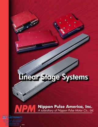
  • 1. Linear Stage Systems Nippon Pulse America, Inc. A subsidiary of Nippon Pulse Motor Co., Ltd. Sold & Serviced By: ELECTROMATE Toll Free Phone (877) SERVO98 Toll Free Fax (877) SERV099 www.electromate.com sales@electromate.com
  • 2. Linear Stages SLP Nanopositioning Series High Precision Linear-Single Axis Stage The SCR Nanopositioning Series offers the accuracy of piezo driven stages with the speed and performance of servo stages. Through complex motion profiles, the SCR series produces extremely accurate results with no loss in stability. As in all Linear Shaft Motor applica-tions, a non-critical air gap produces an environment that is void of any variations in force. The SCR stage also includes an integrated cross-roller guide. With a simple, lightweight, compact shaft-type linear motor comprised of only a magnet and a coil, large drive force is gained with an efficient and short coil length, allowing for high speed and high precision appli-cations. Because there is no friction, there is no sound or dust, making • Moving Stage NPM • Cross-Roller Guide Four SCR stage models allow for design flexibility in high-precision applications • Forcer High Performance Linear-Single Axis Stage There are three SLP models to meet your high-performance needs • Slider • Coil Unit • Linear Guide N i p p o n www.nipponpulse.com P u l s e A m e r i c a , I n c . • Shaft • Linear Encoder SCR AcculinE Series the motor maintenance-free. SLP15 SLP25 SLP35 • Shaft SCR050 SCR075 SCR100 SCR150 A high-precision stage for industrial applications, the SLP Ac-culine Series stages offer superior technology that is unmatched in the industry. As an all-inclusive stage, the SLP stage provides integrated shaft support within the housing and simplifies the transition from conventional ball-screw systems. Because this stage system features a lightweight, compact linear shaft drive, the SLP is a low-profile, high-precision product. The built-in shaft motor is a maintenance free device and also eliminates sound and dust production. The SLP series features the smallest deadzone of any similar stage system available on the market today. In addition, there are no stages on the current market that match the SLP series' force-to-volume ratio, making it an outstanding solution for those with space limita-tions. Sold & Serviced By: ELECTROMATE Toll Free Phone (877) SERVO98 Toll Free Fax (877) SERV099 www.electromate.com sales@electromate.com
  • 3. www.nipponpulse.Linear Stages SCR Stages SCR-050 79 (3.110) A B 28 (1.102) 29 (1.142) 56 (2.205) 12.9 (0.508) 14.5 (0.571) M4 Thread 75.10 (2.957) 29.51 (1.162) M4 Thru-hole 56 (2.205) 29 (1.142) 26.4 (1.039) Stage Specifications Units SCR050-020 SCR050-040 Travel / Stroke mm 20 40 Length mm 75 95 Accuracy μm 2 2 Encoder Resolution μm 1, 0.5, 0.1, 0.05, 0.01 Bi-Directional Repeatability 1 ± 1 count Maximum Acceleration m/s2 20 8 Maximum Velocity 2 m/s 0.6 0.5 Load Capacity 3 kg 10 Moving Mass kg 0.115 0.275 Total Mass g 450 700 Straightness & Flatness μm 2.5/25mm Home Limit Switches Non-contact Magnetic reed switch Home Switch Location Center Limit Switch Over Travel 1 mm Hard Stop Over Travel 2 mm Bearing Cross Roller Bearing Linear Shaft Motor(s) S040Q Note 1: Repeatability +/- 2 counts sub 0.1 um @ Resolu-tions Note 2: For 10nm resolu-tion, max velocity of encoder is limited to 65mm/sec; for 50nm, the limit is 250mm/sec; and for 100nm (0.1μm), the limit is 500mm/sec. Note 3: Please contact our Ap-plications Engineers for loads exceeding 10kg. SCR050-020 100.00 10.00 1.00 0.10 0.0 2.0 4.0 6.0 8.0 10.0 Load Mass Acceleration (m/S2) 700 600 500 400 300 200 100 0 Velocity (mm/s) Acceleration Max Velocity SCR050-040 Acceleration Max Velocity 10.00 1.00 0.10 0.0 2.0 4.0 6.0 8.0 10.0 Load Mass Acceleration (m/S2) 700 600 500 400 300 200 100 0 Velocity (mm/s) MODEL TRAVEL mm A B SCR050-020 20 50 75 SCR050-040 40 75 95 Motor Specifications S040Q (Units) Fund. Motor Constant 0.44 N/√W Motor Force Constant 2.1 N/Arms Back-EMF Constant 0.7 V/m/s Coil Resistance@25°C 22.4 Ω Coil Inductance 1 mH Cont. Current@135°C 0.3 Arms Peak Current 1.1 Arms Cont. Force@135°C 0.58 N Peak Force 2.3 N Cont. Power Rating 3.5 W Thermal Resistance 62.6 °C/W The SCR-050 stage utilizes a S040 Linear Shaft Motor, making it a compact, precise solution for small-scale stage applications. The stage itself contains the cables within a stationary base and like all SCR stages, it utilizes a moving magnet design. With a built-in optical linear encoder that provides sub-micron resolution, the SCR-050 is a complete compact stage solution for small-scale precision movement. Each SCR stage requires a servo driver to operate the stage. Any two SCR stages will bolt directly together to form a very stiff, compact X-Y assembly standard, without the need for adapter plates. Two SCR stages can be supplied as an X-Y stage to insure true orthogonal orientation between the two axes. Stage Specifications Acceleration/Velocity Curves Dimensions Linear Shaft Motor Specifications Motor Cable UL1440 AWG 28 U –red V- White W – black Length: 300mm - 0.3m All units are listed as mm (in) (kg) (kg) 1
  • 4. www.nipponpulse.Linear Stages SCR Stages SCR-075 The SCR-075 stage is a complete single axis stage which integrates a slide guide, encoder and Linear Shaft Motor. It offers a wide range of advantages for applications requiring high performance and accuracy. The Linear Shaft Motor allows for higher resolution, speed, and continuous force than the standard stepper or piezo servomotor. The SCR-075 uses a standard S080 Linear Shaft Motor, however, the coil windings are customizable to a double, triple, or quadruple winding. The SCR-075 features a moving magnet design, a precision ground cross roller and a built-in Each SCR stage requires a servo driver to operate the stage. Any two SCR stages will bolt directly together to form a very stiff, compact X-Y assembly standard, without the need for adapter plates. Two SCR stages can be supplied as an X-Y stage to insure true orthogonal orientation between the two axes. Stage Specifications Note 1 Units SCR075-050 SCR075-100 SCR075-150 Travel / Stroke mm 50 100 150 Length mm 140 190 240 Accuracy μm 3 5 7 Encoder Resolution μm 1, 0.5, 0.1, 0.05, 0.01 Bi-Directional Repeatability Note 2 ± 1 count Maximum Acceleration m/s2 25 20 15 Maximum Velocity Note 3 m/s 1.1 1.4 1.5 Load Capacity Note 4 kg 45.5 Moving Mass kg 0.55 0.7 0.93 Total Mass kg 1 1.3 1.7 Straightness & Flatness μm 2.5/25mm Home Limit Switches Non-contact Magnetic reed switch Home Switch Location Center Limit Switch Over Travel 1 mm Hard Stop Over Travel 2 mm Bearing Cross Roller Bearing Linear Shaft Motor(s) S080D, S080T, S080Q Note 1: Stage specifications are based on the standard motor, the S080Q. Note 2: Repeatability +/- 2 counts sub 0.1 um @ Resolutions Note 3: For 10nm resolution, max velocity of encoder is limited to 65mm/sec; for 50nm, the limit is 250mm/sec; and for 100nm (0.1μm), the limit is 500mm/sec. Note 4: Please contact our Applications Engineers for loads exceeding 45.5kg. Stage Specifications 2 Sold & Serviced By: ELECTROMATE Toll Free Phone (877) SERVO98 Toll Free Fax (877) SERV099 www.electromate.com sales@electromate.com
  • 5. www.nipponpulse.Linear Stages SCR Stages Linear Shaft Motor Specifications Linear Shaft Motor Force Specifications Units S080D S080T S080Q Fundamental Motor Constant N/W 0.98 1.23 1.39 Motor Force Constant (Kf) N/A rms 2.1 3.2 4.2 Back-emf Constant V/m/s 0.7 1.1 1.4 Coil Resistance @ 25°C 4.7 6.8 9.0 Coil Inductance mH 0.7 1 1.3 Continuous Current @ 135°C A 0.84 Peak Current A 3.4 Continuous Force @ 135°C N 1.8 2.7 3.5 Peak Force N 7.2 10.7 14 Continuous Power Rating W 6.6 9.6 12.7 Thermal Resistance °C/W 33.2 22.9 17.3 Dimensions A 55 (2.165) 10 (0.394) 65 (2.559) M4 Thru-hole B 32 (1.26) C 32.5 (1.28) 5 (0.197) 98 (3.858) 65 (2.559) 55 27.5 (2.165) (1.083) M5 Thread MODEL TRAVEL mm A B C SCR075-050 50 N/A 140 N/A SCR075-100 100 115 190 115 SCR075-150 150 165 240 165 Acceleration/Velocity Curves SCR075-050 1200 1000 800 600 400 200 (kg) Acceleration Q coil Max Velocity Q coil 100.00 10.00 1.00 0.10 0.0 9.1 18.2 27.3 36.4 45.5 Load Mass Acceleration (m/S 0 Velocity (mm/s) SCR075-100 100.00 10.00 1.00 0.10 0.0 9.1 18.2 27.3 36.4 45.5 Load Mass Acceleration (m/S 1600 1400 1200 1000 800 600 400 200 0 Velocity (mm/s) (kg) Acceleration Q coil Max Velocity Q coil SCR075-150 100.00 10.00 1.00 0.10 0.0 9.1 18.2 27.3 36.4 45.5 Load Mass Acceleration (m/S 1600 1400 1200 1000 800 600 400 200 0 Velocity (mm/s) Acceleration Q coil Max Velocity Q coil Motor Cable Lapp Unitronic 190-602803 AWG 28 U –red V- White W – black Length 3000mm All units are listed as mm (in) (kg) SCR-075 Note: Curves apply only to the stage’s standard motor, the S080Q. If you are interested in using the S080D or S080T in your stage, please contact our application engineers to learn more about the acceleration and velocity for those coils. ELECTROMATE Toll Free Phone (877) SERVO98 Toll Free Fax (877) SERV099 www.electromate.com sales@electromate.com 3 Sold & Serviced By:
  • 6. www.nipponpulse.Linear Stages SCR Stages SCR-100 With six different stroke lengths and three different motor windings, the SCR- 100 stage is the most versatile of the SCR lineup. Like its relatives, the SCR-100 integrates a slide guide, encoder, and a Linear Shaft Motor. A wide range of options allows for a better match for stage applications needing sub-micron resolution that is free from motion errors. Each SCR stage requires a servo driver to operate the stage. Any two SCR stages will bolt directly together to form a very stiff, compact X-Y assembly standard, without the need for adapter plates. Two SCR stages can be supplied as an X-Y stage to insure true orthogonal orientation between the two axes. Stage Specifications Specifications Note 1 Units SCR100-050 SCR100-100 SCR100-150 SCR100-200 SCR100-250 SCR100-300 Travel / Stroke mm 50 100 150 200 250 300 Length mm 140 190 240 290 340 390 Accuracy μm 3 5 7 9 11 12 Encoder Resolution μm 1, 0.5, 0.1, 0.05, 0.01 Bi-Directional Repeatability Note 2 ±1 count Maximum Acceleration m/s2 17 12 10 8 7 6 Maximum Velocity Note 3 m/s 0.9 1 1.2 1.2 1.3 1.3 Load Capacity Note 4 kg 45.5 Moving Mass kg 0.8 1.1 1.3 1.6 2.0 2.2 Total Mass kg 1.6 2.1 2.6 3.2 3.9 4.5 Straightness & Flatness μm 2/25mm Home Limit Switches Non-contact, Magnetic reed switch Home Switch Location Center Limit Switch Over Travel mm 1 Hard Stop Over Travel mm 2 Bearing Cross roller bearing Linear Shaft Motor(s) S080D, S080T, S080Q Note 1: Stage specifications are based on the standard motor, the S080Q. Note 2: Repeatability +/- 2 counts sub 0.1 um @ Resolutions Note 3: For 10nm resolution, max velocity of encoder is limited to 65mm/sec; for 50nm, the limit is 250mm/sec; and for 100nm (0.1μm), the limit is 500mm/sec. Note 4: Please contact our Applications Engineers for loads exceeding 45.5kg. Sold & Serviced By: ELECTROMATE Toll Free Phone (877) SERVO98 Toll Free Fax (877) SERV099 www.electromate.com sales@electromate.com 4
  • 7. www.nipponpulse.Linear Stages Linear Shaft Motor Specifications A 72 (2.835) 14 (0.551) 89 (3.504) M4 Thru-hole 5.5 (0.217) M5 Thread C 123 (4.843) 89 (3.504) 36 (1.417) 72 (2.835) 44.5 (1.752) B 34 (1.339) SCR Stages Linear Shaft Motor Force Specifications Units S080D S080T S080Q Fundamental Motor Constant N/W 0.98 1.23 1.39 Motor Force Constant (Kf) N/A rms 2.1 3.2 4.2 Back-emf Constant V/m/s 0.7 1.1 1.4 Coil Resistance @ 25°C 4.7 6.8 9 Coil Inductance mH 0.7 1 1.3 Continuous Current @ 135°C A 0.84 Peak Current A 3.4 Continuous Force @ 135°C N 1.8 2.7 3.5 Peak Force N 7.2 10.7 14 Continuous Power Rating W 6.6 9.6 12.7 Thermal Resistance °C/W 33.2 22.9 17.3 Acceleration/Velocity Curves SCR100-100 100.00 10.00 1.00 100.00 10.00 1.00 0.10 0.0 9.1 18.2 27.3 36.4 45.5 Load Mass Acceleration (m/s2) 1000 900 800 700 600 500 400 300 200 1200 1000 800 s) mm/600 (400 Velocity 200 0 (kg) Acceleration Q coil Max Velocity Q coil SCR100-150 100.00 1400 1200 Acceleration (m/s2) 0 10.00 1.00 0.10 0.0 9.1 18.2 27.3 36.4 45.5 Load Mass 1000 800 600 400 200 Velocity (mm/s) Acceleration Q coil Max Velocity Q coil SCR100-200 10.00 1.00 0.10 0.0 9.1 18.2 27.3 36.4 45.5 Load Mass Acceleration (m/s2) 1400 1200 1000 800 600 400 200 0 Velocity (mm/s) Acceleration Q coil Max Velocity Q coil SCR100-250 10.00 1.00 0.10 0.0 9.1 18.2 27.3 36.4 45.5 Load Mass Acceleration (m/s2) 1400 1200 1000 800 600 400 200 0 Velocity (mm/s) Acceleration Q coil Max Velocity Q coil SCR100-300 10.00 1.00 0.10 0.0 9.1 18.2 27.3 36.4 45.5 Load Mass Acceleration (m/s2) 1400 1200 1000 800 600 400 200 0 Velocity (mm/s) Acceleration Q coil Max Velocity Q coil Note: Curves apply only to the stage’s standard motor, the S080Q. If you are interested in using the S080D or S080T in your stage, please contact our application engineers to learn more about the acceleration and velocity for those coils. Dimensions MODEL TRAVEL mm A B C SCR100-050 50 N/A 140 N/A SCR100-100 100 120 190 120 SCR100-150 150 160 240 160 SCR100-200 200 200 290 200 SCR100-250 250 260 340 260 SCR100-300 300 300 390 300 SCR100-050 0.10 0.0 9.1 18.2 27.3 36.4 45.5 Load Mass Acceleration (m/s2) 0100 Velocity (mm/s) Acceleration Q coil Max Velocity Q coil Motor Cable Lapp Unitronic 190-602803 AWG 28 U –red V- White W – black Length 3000mm All units are listed as mm (in) (kg) (kg) (kg) (kg) (kg) SCR-100 5
  • 8. Linear Stages Specifications www.nipponpulse.SCR-150 The largest of the SCR stages, the SCR-150 stage has stroke lengths up to 300 mm while maintaining the high performance and accuracy of the smaller SCR stages. Like the other three stages, the SCR 150 is a complete single axis stage which integrates a slide guide, encoder, and a Linear Shaft Motor. It offers a wide range of advantages for applications requiring high performance and accuracy. Each SCR stage requires a servo driver to operate the stage. Any two SCR stages will bolt directly together to form a very stiff, compact X-Y assembly standard, without the need for adapter plates. Two SCR stages can be supplied as an X-Y stage to insure true orthogonal orientation between the two axes. Stage Specifications Note 1 Units SCR150-100 SCR150-150 SCR150-200 SCR150-250 SCR150-300 Travel / Stroke Note 2 mm 100 150 200 250 300 Length mm 230 280 330 380 430 Stroke mm 100 150 200 250 300 Accuracy μm 5 7 9 11 12 Encoder Resolution μm 1, 0.5, 0.1, 0.05, 0.01 Bi-Directional Repeatability Note 3 ±1 count Maximum Acceleration m/s2 17 13 11 9 8 Maximum Velocity Note 4 m/s 1.3 1.3 1.4 1.5 1.5 Load Capacity Note 5 kg 45.5 Moving Mass kg 2.3 2.9 3.5 4.1 4.7 Total Mass kg 5.2 6.5 7.9 9.2 10.6 Straightness & Flatness μm 2/25mm Home Limit Switches Non-contact, Magnetic reed switch Home Switch Location Center Limit Switch Over Travel mm 1 Hard Stop Over Travel mm 2 Bearing Cross roller bearing Linear Shaft Motor(s) S160D, S160T, S160Q Note 1: Specifications based on standard motor, S160D Note 2: Travel/Stroke with S160D coil; when using S160T, stroke is 30mm shorter; when using S160Q, stroke is 60mm shorter Note 3: Repeatability +/- 2 counts sub 0.1 um @ Resolutions Note 4: For 10nm resolution, max velocity of encoder is limited to 65mm/sec; for 50 m, the limit is 250mm/sec; and for 100 m (0.1μm), the limit is 500mm/sec. Note 5: Please contact our Applications Engineers for loads exceeding 45.5kg. SCR Stages Sold & Serviced By: ELECTROMATE Toll Free Phone (877) SERVO98 Toll Free Fax (877) SERV099 www.electromate.com sales@electromate.com 6
  • 9. www.nipponpulse.Linear Stages SCR Stages Linear Shaft Motor Specifications 113 (4.449) 18.5 (0.728) 125 (4.921) A B Thru-hole 125 4.921 C 182.18 (7.172) 11.09 (0.437) M6 Thread 113 (4.449) 56.5 (2.224) 62.5 (2.461) 113 (4.449) SCR150-150 100.00 10.00 1.00 100.00 10.00 1.00 0.10 0.0 9.1 18.2 27.3 36.4 45.5 Load Mass Acceleration (m/S2) 1600 1400 1200 1000 800 600 400 200 1800 1600 1400 1200 1000 800 600 400 200 0 Velocity (mm/s) Acceleration D coil Max Velocity D coil SCR150-200 100.00 10.00 1.00 0.10 0.0 9.1 18.2 27.3 36.4 45.5 Load Mass Acceleration (m/S2) 2000 1800 1600 1400 1200 1000 800 600 400 0200 Velocity (mm/s) Acceleration D coil Max Velocity D coil SCR150-250 100.00 10.00 1.00 0.10 0.0 9.1 18.2 27.3 36.4 45.5 Load Mass Acceleration (m/S2) 2500 2000 1500 1000 500 0 Velocity (mm/s) Acceleration D coil Max Velocity D coil SCR150-300 100.00 10.00 1.00 0.10 0.0 9.1 18.2 27.3 36.4 45.5 Load Mass Acceleration (m/S2) 2500 2000 1500 1000 500 0 Velocity (mm/s) Acceleration D coil Max Velocity D coil Linear Shaft Motor Force Specifications Units S160D S160T S160Q Fundamental Motor Constant N/W 3.51 4.2 4.96 Motor Force Constant (Kf) N/A rms 16 24 33 Back-emf Constant V/m/s 5.4 8.1 11 Coil Resistance @ 25°C 21 33 43 Coil Inductance mH 8.2 12 16 Continuous Current @ 135°C A 0.6 Peak Current A 2.5 Continuous Force @ 135°C N 10 15 20 Peak Force N (lb) 40 60 80 Continuous Power Rating W 16.1 25.4 33.1 Thermal Resistance °C/W 33.2 22.9 17.3 SCR150-100 0.10 0.0 9.1 18.2 27.3 36.4 45.5 Load Mass Acceleration (m/S2) 0 Velocity (mm/s) Acceleration D coil Max Velocity D coil MODEL TRAVEL mm A B C SCR150-100 100 N/A 230 N/A SCR150-150 150 175 280 175 SCR150-200 200 225 330 225 SCR150-250 250 275 380 275 SCR150-300 300 325 430 325 Acceleration/Velocity Curves Dimensions Motor Cable UL2464 AWG 24 U –orange V- white W – gray Length 300mm All units are listed as mm (in) (kg) (kg) (kg) (kg) (kg) SCR-150 Note: Curves apply only to the stage’s standard motor, the S160D. If you are interested in using the S160T or S160Q in your stage, please contact our application engineers to learn more about the acceleration and velocity for those coils. 7
  • 10. www.nipponpulse.Linear Stages Rated Spec Unit Specification Encoder μm 1 (HEIDENHAIN LIDA279) Continuous Force N 17 Peak Force*1 N 90 Continuous Current*2 A 0.51 Peak Current*1 A 2.7 Force Constant (Kf) N/A rms 33 Back EMF V/m/s 11 Resistance*3 ohm 56 Inductance*3 mH 24 Magnetic Pitch (N-N) mm 60 Maximum Acceleration*4 G 3.5 Maximum Velocity*4, *5 m/s 3 Repeatability mm ±0.0005 Max Load, Horizontal kg 5 Max Load, Wall kg 3 Stroke, Single Forcer*6 mm 100~1300 (100 interval) Stroke, Double Forcer*6 mm 100~1200 (100 interval) Operating Temperature °C 0~+40 Operating Humidity % 20~80 (no condensation) Storage Temperature °C −20~+60 Moving Mass kg 0.5 SLP15 • High Thrust, High Speed, High Responsiveness, High Precision, Long Stroke • Simple Design and Easy Installation • No-Contact Drive means Low Noise, Long Lifespan, and Maintenance-Free *1 – Peak Force given is based on the output with the use of the following driver: SLP15: (14) Hitachi Production Machine System ADA3-01LL2 *2 – The effective amperage when the temperature increase of the coil front becomes 110K. *3 – An average value of U-V, U-W, and V-W. *4 – There are instances when this is not achieved due to load or operation specifications. *5 – There are instances when this is not achieved due to the length of the stroke. *6 – Please inquire further concerning strokes not explained. SLP Stages F-V Curve SLP15 F‑V Curve GHR15 Acc. Force Cont. Force Acc. Force Cont. Force 0 1 2 3 4 0 1 2 3 4 VVeelolcoictyi t(my,/ sm)/s 100 100 90 90 80 80 70 70 60 60 50 50 40 40 30 30 20 20 10 10 0 0 Velocity, m/s Force, N ※j駆動hラ*C oDにriXv日en立 bY@yV XAeDムA A3D-0A31‑L0L12LL 2dをrivgepしr wたi場th 合2の00f[ A^でCす inBput. Force (N) Max. Acceleration vs. Load Load (kg) Max Acceleration (G) 6 5.5 5 4.5 4 3.5 3 2.5 2 1.5 1 0.5 0 A-L Curve SLP15 0 1 2 3 4 5 6 * Driven by ADA3-01LL2 driver with 200 AC input. 5 4 3 2 1 0 -1 -2 -3 -4 -5 1 2 3 4 5 6 7 Count Error (μm) Repeatability SLP15 Overhanging Weight Tolerance (in mm) Load 0° 45° 90° Horizontal 1kg 380 400 450 2kg 220 250 270 3kg 160 190 200 4kg 120 140 150 5kg 100 110 130 Wall 1kg 440 390 320 2kg 260 230 180 3kg 180 170 120 90° 45° 0° Stage Specifications F-V Curve Position Repeatability
  • 11. www.nipponpulse.Linear Stages SLP15 Single Slider Dimensions 5 Double Slider Dimensions Sold & Serviced By: ELECTROMATE Toll Free Phone (877) SERVO98 Toll Free Fax (877) SERV099 www.electromate.com sales@electromate.com N = number of holes on stage Encoder Cable Specifications Heidenhain Outer Diameter ø 4.3 mm Dsub 15 Pin Connector (Male) Stroke (mm) L (mm) N Weight (Kg) 100 420 4 3.0 200 520 5 3.5 300 620 6 3.9 400 720 7 4.3 500 820 8 4.8 600 920 9 5.2 700 1020 10 5.6 800 1120 11 6.1 900 1220 12 6.5 1000 1320 13 6.9 1100 1420 14 7.4 1200 1520 15 7.8 2.6 1 5.8 3.3 Detail For P&Q 10 (Including Mechanical Stop) 4-M4 Depth 10 2-φH7 Depth 10 Stroke 10 (Including Mechanical Stop) L Encoder Cable Motor Power Supply Cable 140 25 45 45 82 88 48 84 10 40 40 40 P Q For Frame Ground Travel FG Label 4-M3 Depth 4 Opposite side is the same 60 100 60 46 2 x N-M3 Depth 5 Pitch 100 x (N-1) 2 x N - φ3.5 Drill φ6 Countersink Depth 3 (From Rear) Power Supply Cable Specifications Hitachi Cable UL2464 AWG 25 Outer Diameter ø 4.3mm JST XM Connector (Male) 3.3 Detail For P&Q 10 (Including Mechanical Stop) 4-M4 Depth 10 2-φH7 Depth 10 5 (Mechanical Stop) 5 (Mechanical Stop) Encoder Cable Motor Power Supply Cable P Q For Frame Ground Travel FG Label 4-M3 Depth 4 Opposite side is the same 2 x N-M3 Depth 5 Pitch 100 x (N-1) 2 x N - φ3.5 Drill φ6 Countersink Depth 3 (From Rear) Stroke 20 (Including Mechanical Stop) L Encoder Cable Specifications Heidenhain Outer Diameter ø 4.3 mm Dsub 15 Pin Connector (Male) 88 48 84 5.8 60 46 7 2.6 1 140 25 45 45 10 40 40 40 5 60 100 (80) (80) 140 (80) (80) SLP Stages All units are listed as mm All units are listed as mm (80) (80) Stroke (mm) L (mm) N Weight (Kg) 100 270 3 1.8 200 370 4 2.2 300 470 5 2.6 400 570 6 3.1 500 670 7 3.5 600 770 8 4.0 700 870 9 4.4 800 970 10 4.8 900 1070 11 5.3 1000 1170 12 5.7 1100 1270 13 6.1 1200 1370 14 6.6 1300 1470 15 7.0 9 Power Supply Cable Specifications Hitachi Cable UL2464 AWG 25 Outer Diameter ø 4.3mm JST XM Connector (Male) N = number of holes on stage
  • 12. www.nipponpulse.Linear Stages Rated Spec Unit Specification Encoder μm 1 (HEIDENHAIN LIDA279) Continuous Force N 80 Peak Force*1 N 340 Continuous Current*2 A 1.2 Peak Current*1 A 5.1 Force Constant (Kf) N/A rms 66 Back EMF V/m/s 22 Resistance*3 ohm 8.4 Inductance*3 mH 15 Magnetic Pitch (N-N) mm 90 Maximum Acceleration*4 G 3.5 Maximum Velocity*4, *5 m/s 3 Repeatability mm ±0.0005 Max Load, Horizontal kg 30 Max Load, Wall kg 15 Stroke, Single Forcer*6 mm 200-1200 (100 interval) Stroke, Double Forcer*6 mm 200-1200 (100 interval) Operating Temperature °C 0~+40 Operating Humidity % 20~80 (no condensation) Storage Temperature °C −20~+60 Moving Mass kg 2.7 • High Thrust, High Speed, High Responsiveness, High Precision, Long Stroke • Simple Design and Easy Installation • No-Contact Drive means Low Noise, Long Lifespan, and Maintenance-Free Stage Specifications F-V Curve *1 – Peak Force given is based on the output with the use of the following driver: SLP15: (14) Hitachi Production Machine System ADA3-01LL2 *2 – The effective amperage when the temperature increase of the coil front becomes 110K. *3 – An average value of U-V, U-W, and V-W. *4 – There are instances when this is not achieved due to load or operation specifications. *5 – There are instances when this is not achieved due to the length of the stroke. *6 – Please inquire further concerning strokes not explained. Load 0° 45° 90° Horizontal 5kg 1000 1000 1000 10kg 1000 800 1000 15kg 800 650 1000 20kg 700 580 1000 25kg 550 500 1000 30kg 500 450 1000 Wall 3kg 1000 1000 1000 6kg 1000 800 450 9kg 1000 670 400 12kg 1000 580 350 15kg 1000 500 300 90° 45° 0° SLP Stages F-V Curve SLP25 F‑V Curve GHR25 Acc. Force Cont. Force Acc. Force Force 0 1 2 3 4 Velocity, m/s Force (N) Velocity (m/s) 400 350 300 250 200 150 100 50 0 * Driven by ADA3-01LL2 driver with 200 AC input. Max. Acceleration vs. Load Load (kg) Max Acceleration (G) 6 5.5 5 4.5 4 3.5 3 2.5 2 1.5 1 0.5 0 A-L Curve SLP25 0 10 20 30 40 * Driven by ADA3-01LL2 driver with 200 AC input. 5 4 3 2 1 0 -1 -2 -3 -4 -5 1 2 3 4 5 6 7 Count Error (μm) Repeatability SLP25 Overhanging Weight Tolerance (in mm) Position Repeatability SLP25 10
  • 13. www.nipponpulse.Linear Stages SLP Stages SLP Stages Sold & Serviced By: ELECTROMATE Toll Free Phone (877) SERVO98 Toll Free Fax (877) SERV099 www.electromate.com sales@electromate.com Motor Power Supply Cable Specifications Hitachi Cable UL2570 AWG 18 Outer Diameter ø 6.1 JST HL Connector (male) Encoder Cable Specifications Heidenhain Outer Diameter ø 4.3 Dsub 15 Pin Connector (Male) 162 30 50 50 50 12.5 (Including mechanical stop) 2-ø6H7 Depth 15 150 210 65 65 4-M6 Depth 15 (100) (100) L Stroke 27.5 (Including mechanical stop) Encoder Cable Encoder Cable 75 100 66 100 13 5.3 8.5 4.5 2 Pitch 100 x (N-1) 2xN-M6 Depth 10 2xN-ø6.5 Drill φ6 Countersink Depth 3 (From rear) P Q 79 147 For frame ground terminal 11 FG label Motor Power Supply Cable Specifications Hitachi: Power Supply Co. UL2570 AWG 18 Outer Diameter ø 6.1 JST HL Connector (male) Encoder Cable Specifications Heidenhain Outer Diameter ø 4.3 Dsub 15 Pin Connector (Male) Stroke (mm) L (mm) N Weight (Kg) 200 670 7 16 300 770 8 17 400 870 9 19 500 970 10 20 600 1070 11 22 700 1170 12 23 800 1270 13 24 900 1370 14 26 1000 1470 15 27 1100 1570 16 28 1200 1670 17 30 162 30 50 50 50 12.5 (Including mechanical stop) 4-M6 Depth 15 2-ø6H7 Depth 15 150 210 65 65 (100) (100) L Stroke 27.5 (Including mechanical stop) Encoder Cable Power Supply Cable 35 100 66 100 13 5.3 8.5 4.5 2 Pitch 100 x (N-1) 2xN-M6 Depth 10 2xN-ø6.5 Drill φ11 Countersink Depth 6.5 (From rear) P Q 79 147 For frame ground terminal 11 FG label 5 (mechanical stop) 5 (mechanical stop) 11 For frame ground terminal FG label Single Slider Dimensions Double Slider Dimensions All units are listed as mm (100) (100) All units are listed as mm SLP25 Detail For P&Q Detail For P&Q Stroke (mm) L (mm) N Weight (Kg) 200 450 5 9.7 300 550 5 11 400 650 6 12 500 750 7 14 600 850 8 15 700 950 9 16 800 1050 10 18 900 1150 11 19 1000 1250 12 20 1100 1350 13 22 1200 1450 14 23 N = number of holes on stage N = number of holes on stage
  • 14. www.nipponpulse.Linear Stages Rated Spec Unit Specification Encoder μm 1 (HEIDENHAIN LIDA279) Continuous Force N 185 Peak Force*1 N 970 Continuous Current*2 A 2.7 Peak Current*1 A 14.4 Force Constant (Kf) N/A rms 68 Back EMF V/m/s 22 Resistance*3 ohm 7.2 Inductance*3 mH 12 Magnetic Pitch (N-N) mm 120 Maximum Acceleration*4 G 3.5 Maximum Velocity*4, *5 m/s 3 Repeatability mm ±0.0005 Max Load, Horizontal kg 60 Max Load, Wall kg 30 Stroke, Single Forcer*6 mm 300-1200 (100 interval) Stroke, Double Forcer*6 mm 300-900 (100 interval) Operating Temperature °C 0~+40 Operating Humidity % 20~80 (no condensation) Storage Temperature °C −20~+60 Moving Mass kg 4.4 • High Thrust, High Speed, High Responsiveness, High Precision, Long Stroke • Simple Design and Easy Installation • No-Contact Drive means Low Noise, Long Lifespan, and Maintenance-Free *1 – Peak Force given is based on the output with the use of the following driver: SLP15: (14) Hitachi Production Machine System ADA3-01LL2 *2 – The effective amperage when the temperature increase of the coil front becomes 110K. *3 – An average value of U-V, U-W, and V-W. *4 – There are instances when this is not achieved due to load or operation specifications. *5 – There are instances when this is not achieved due to the length of the stroke. *6 – Please inquire further concerning strokes not explained. Overhanging Weight Tolerance (in mm) 90° 45° 0° Stage Specifications F-V Curve SLP Stages F-V Curve SLP35 F‑V Curve GHR25 Acc. Force Acc. Force Cont. Force 0 1 2 3 4 Velocity (m/s) Velocity, m/s Force (N) 1200 1000 800 600 400 200 0 * Driven by ADA3-01LL2 driver with 200 AC input. Max. Acceleration vs. Load A-L Curve SLP35 0 10 20 30 40 50 60 70 Load (kg) Max Acceleration (G) 6 5.5 5 4.5 4 3.5 3 2.5 2 1.5 1 0.5 0 * Driven by ADA3-01LL2 driver with 200 AC input. Position Repeatability 5 4 3 2 1 0 -1 -2 -3 -4 -5 1 2 3 4 5 6 7 Count Error (μm) Repeatability SLP35 SLP35 Sold & Serviced By: 12 Cont. Force Load 0° 45° 90° Horizontal 10kg 1000 1000 1000 20kg 1000 900 1000 30kg 940 780 1000 40kg 840 660 1000 50kg 750 590 950 60kg 680 540 900 Wall 5kg 1000 1000 700 10kg 1000 900 600 15kg 1000 810 520 20kg 1000 710 430 25kg 980 620 350 30kg 890 530 300 ELECTROMATE Toll Free Phone (877) SERVO98 Toll Free Fax (877) SERV099 www.electromate.com sales@electromate.com
  • 15. www.nipponpulse.Linear Stages Sold & Serviced By: ELECTROMATE Toll Free Phone (877) SERVO98 Toll Free Fax (877) SERV099 www.electromate.com sales@electromate.com Motor Power Supply Cable Specifications Hitachi Cable UL2570 AWG 18 Outer Diameter ø 6.1 JST HL Connector (male) Encoder Cable Specifications Heidenhain Outer Diameter ø 4.3 Dsub 15 Pin Connector (Male) Stroke (mm) L (mm) N Weight (Kg) 300 630 6 17 400 730 7 30 500 830 8 21 600 930 9 23 700 1030 10 25 800 1130 11 26 900 1230 12 28 1000 1330 13 30 1100 1430 14 32 1200 1530 15 34 Motor Power Supply Cable Specifications Hitachi Cable UL2570 AWG 18 Outer Diameter ø 6.1 JST HL Connector (male) Encoder Cable Specifications Heindenhain Outer Diameter ø 4.3 Dsub 15 Pin Connector (Male) Stroke (mm) L (mm) N Weight (Kg) 300 920 9 28 400 1020 10 30 500 1120 11 32 600 1220 12 33 700 1320 13 35 800 1420 14 37 900 1520 15 39 SLP35 186 30 50 50 50 20 (Including mechanical stop) 2-ø6H7 Depth 15 170 280 90 90 4-M8 Depth 15 (140) (140) L Stroke 30 (Including mechanical stop) Encoder Cable Power Supply Cable 65 100 84 110 5.3 18 8.5 4.5 2 Pitch 100 x (N-1) 2xN-M6 Depth 10 2xN-ø6.5 Drill φ11 Countersink Depth 6.5 (From rear) P Q 90 163 For frame ground terminal 13 FG label Single Slider Dimensions Double Slider Dimensions 186 35 70 70 70 20 (Including mechanical stop) 4-M8 Depth 15 2-ø6H7 Depth 15 170 280 90 90 (140) L Stroke 30 (Including mechanical stop) Encoder Cable Power Supply Cable 60 100 84 110 13 5.3 8.5 4.5 2 Pitch 100 x (N-1) 2xN-M6 Depth 10 2xN-ø6.5 Drill φ6.5 Countersink Depth 6.5 (From rear) P Q 90 163 For frame ground terminal 11 FG label 5 (mechanical stop) 5 (mechanical stop) 13 For frame ground terminal FG label 280 4-M5 Depth 10 SLP Stages All units are listed as mm (140) All units are listed as mm (140) (140) 13 Detail For P&Q Detail For P&Q N = number of holes on stage N = number of holes on stage
  • 16. www.nipponpulse.Linear Stages 1 2 3 4 5 6 7 8 9 10 11 12 13 14 15 Orthogonal Jig Plate for use with SLP X-Y table When constructing a multiple-axis table utilizing several SLP Series, installation is exceptionally easy with the placement of this jig in-between the axes. It is also possible to easily gain orthogonal precision between the lower axis and the upper axis by positioning the two attached positioning pins to the precision holes on the face of the stage’s slider installation. However, because there is a limit to the possible combinations between models, please use the models suitable for multiple axes. Z Plates are also available for three-dimensional motion. Jig plates are not needed for SCR Stages multi-axis arrangements. SLP Pinout Pin Signal Wire Color 1 A+ White 2 0V Black/Red 3 B+ Green 4 5V Red 7 Z- Black/Yellow 9 A- Black/White 11 B- Black/Green 14 Z+ Yellow SCR Standard Pinout Pin Signal 2 0V 4 Z- 5 B- 6 A- 7 5V 8 5V 9 0V 12 Z+ 13 B+ 14 A+ 15 shield SLP Cable Options Application Examples Loader/Unloader Multiple sliders move indepen-dently at high precision. Use of a multi-slider enhances cost-cutting and saves space. • • Substrate Conveyance Device By placing the lower shafts in a parallel position it is possible to place work in the central space. Moreover, the shaft motors can be driven with one driver or in parallel motion. • • Standard X-Y Arrangement Due to the many number of ways in which the SLP15, SLP25 and SLP35 can be used together, high speed and a wide range of movement are possible. • Option A - Use wire color Option B - Use pin number SCR X-Y Arrangement Pinouts and Applications Sold & Serviced By: ELECTROMATE Toll Free Phone (877) SERVO98 Toll Free Fax (877) SERV099 www.electromate.com sales@electromate.com 14
  • 17. www.nipponpulse.Linear Stages SCR Stage Part Number Guide Example model number: SCR100-50-010-08Q Stage Width (mm) Stroke (mm) Encoder Motor Size End Limits Hall Effects — — — — — SCR XXX XXX XXX X XX Blank = No End Limits 1 = End Limits XXD = Motor Size with double winding XXT = Motor Size with triple winding XXQ = Motor Size with quadruple winding 100 = 1 mm 050 = 0.5 mm 010=0.1 mm 005 = 50 nm 001 = 10 nm 50 mm (1.97 in) 100 mm (3.94 in) 150 mm (5.91 in) 200 mm (7.88 in) 250 mm (9.85 in) 300 mm (11.82 in) XX Stage Width in mm Stage Main Body Model 050 075 100 150 SLP Stage Part Number Guide Frame Cable Size Stroke Slide Carrier Jig Plate SLP XXXX X XX XXXX Blank = No Orthogonal Jig Plate XYPA = Orthogonal Jig Plate A XYPB = Orthogonal Jig Plate B XZP = Z-Axis Jig Plate (When ordering a jig plate, you get one jig plate per slider). S = 1 slide D = 2 slides Stroke Length (mm) 100 - 2000 (100 mm increments) 15, 25, 35 = Frame Size Stage Main Body Model — — — — 15 25 35 Blank = No Cable Carrier SH = S -Type Horizontal Mount SW = S-Type Wall Mount MH = M-Type Horizontal Mount MW = M Type Wall Mount Part Number Guide — Blank = No Hall Effects HA = Hall Effects 15 Example model number: SLP15-200-S-SH SL-M3: 3m motor cable SL-M6: 6m motor cable SL-M9: 9m motor cable SL-A3: Single-end D-sub 3m SL-A6: Single-end D-sub 6m SL-A9: Single-end D-sub 9m SL-B3: Double-end D-sub 3m SL-B6: Double-end D-sub 6m SL-B9: Double-end D-sub 9m SLP Motor Cable Part Numbers SLP Encoder Cable Part Numbers Sold & Serviced By: ELECTROMATE Toll Free Phone (877) SERVO98 Toll Free Fax (877) SERV099 www.electromate.com sales@electromate.com
  • 18. Linear Stages 48 www.nipponpulse.75 88 58 SLP 15 M-Type Cable Carrier Cable Carriers Vertical Vertical 72 48 10.3 16 16 10.3 48 75 88 58 88 74 48 10.3 30 10.3 30 88 SLP 25 S-Type Cable Carrier SLP 25 M-Type Cable Carrier SLP 35 S-Type Cable Carrier SLP 35 M-Type Cable Carrier 186 90 46 82.5 16 10.3 Vertical Vertical Vertical Vertical 62.5 90 186 16 10.3 186 90 46 82.5 62.5 90 186 30 10.3 30 10.3 162 79 44 74.5 66.5 79 162 10.3 16 10.3 16 162 79 44 74.5 66.5 79 162 30 10.3 30 10.3 SLP Cable Carrier Dimensions SLP 15 S-Type Cable Carrier Horizontal Horizontal Horizontal Horizontal Horizontal Horizontal Custom Stages In addition to the two standard stage series, Nippon Pulse America also has the ability to build custom stages to fit a client's applications. Please contact Nippon Pulse America or a local representative for more information and pricing of a custom stage unit. To provide better support, a custon stage worksheet is available from NPA. Click the link below to download the worksheet. It is also available on the Nippon Pulse America web site. Follow the 'Product Manual' link and find the link at the bottom of the page. Complete this form and return it to NPA to make custom staging more efficient. Sold & Serviced By: 16 Custom Stage Worksheet ELECTROMATE Toll Free Phone (877) SERVO98 Toll Free Fax (877) SERV099 www.electromate.com sales@electromate.com
  • 19. www.nipponpulse.Linear Stages Basic Structure of a Linear Shaft Motor Linear Shaft Motor The Next Generation In Linear Motion What is a Linear Shaft Motor? The underlying motor technology in Nippon Pulse's Stage units is the Linear Shaft Motor. A high precision direct drive linear servomotor, the Linear Shaft Motor consists of a shaft of Rare Earth-Iron-Boron Permanent (NIB) Magnets and a “forcer” of cylindrically wound coils which can be supplied with optional Hall Effect devices. The shaft supplies the magnetic field which the forcer acts upon. The forcer assembly, combined with the amplifier and control electronics, produces the force for the motor. The Hall Effect devices can be supplied, if they are required by your selected servo driver for proper commutation of a brushless linear motor and are integrated into the forcer assembly. The Linear Shaft Motor was designed with three basic design concepts: Linear Shaft Motors are simple. They consist of only two parts, a magnetic shaft, and a “forcer” of cylindrically wound coils. Linear Shaft Motors provide ultra high precision. They have no iron in the forcer or shaft thus giving you the precision and zero cogging expected in a coreless design. The coils of the Linear Shaft Motor themselves form the core thus giving you the stiffness expected in an iron cored motor. Linear Shaft Motor is non-contact. Since the coil completely wraps around the magnets, all the magnetic flux is efficiently used. This allows for a large (0.5 to 2.5mm) nominal annular air gap. This air gap is non-critical, meaning there is no variation in force as the gap varies over the stroke of the device. The magnetic structure of the Shaft is built in such a manner that there is no space between each magnet and is fully supported within itself. The magnetic structure is then inserted into a protective stainless steel tube. This patented process is protected by numerous patents throughout the world. The patented process used by the Linear Shaft Motor produces a very strong magnetic field which is twice that of other linear motors. U W U W Forcer Construction The coils of the Linear Shaft Motor are of a cylindrical design, thus providing a number of key advantages over other linear motors. • The cylindrical design of the coils makes the coil assembly very stiff without the use of external stiffening materials, such as the iron used by platen style linear motors. • The coils surround the magnets allowing for the optimal use of all the magnetic flux. This makes the air gap non-critical. As long as the forcer does not come in contact with the shaft there is no variation in the linear force. • The magnetic flux cuts motor windings at right angles for max efficiency. • All sides of the coil are positioned to allow for maximum dissipation of heat. • The Linear Shaft Motor requires less current and less mass, to produce a similar force, and is more efficient than any other linear motor on the market. Sold & Serviced By: Shaft Magnet Forcer Coil Gap Magnetic Flux N S S N N S S N N S S N U W U W Gap Stainless Steel Shaft Motor Coil (Forcer) Shaft Magnetic Flux Force High Energy Magnet ELECTROMATE Toll Free Phone (877) SERVO98 Toll Free Fax (877) SERV099 www.electromate.com sales@electromate.com
  • 20. Linear Stages The Nippon Pulse Advantage For nearly sixty years, Nippon Pulse has built state-of-of-the-art products based on a solid foundation of advancing technology and thorough product research. Nippon Pulse America, Inc. (NPA) faithfully provides these high-quality products to a wide range of industries in North and South America and Europe. NPA has established itself as a leader in stepper motor, driver, and controller technology while introducing innovative products such as the Linear Shaft Motor and MotionNet. At NPA, we believe that by bringing products to market which not only meet customers’ requirements, but actually impress them, we contribute to the progression of technology and its positive impact on our society. We pride ourselves on the reputation of our high-quality products that provide that impact. A wholly owned subsidiary of Nippon Pulse Motor Co., Ltd., Nippon Pulse America is headquartered in Radford, Va. NPA has representatives throughout North and South America and Europe to directly assist customers. Limited quantities of stock on standard motors and electronics are available to allow faster response to customer needs. In addition, Nippon Pulse America has a model shop in its headquarters for quick turnaround on custom prototypes and special orders. NPA’s mission is to faithfully create the new products sought by its customers and to contribute to the development of society from a global viewpoint. When you choose a Nippon Pulse motor, driver, controller, network or stage, you’re doing more than just buying a quality product. You’re benefitting from what we call the Nippon Pulse Advantage. This includes superior prototyping, complete system engineering, proper compliance and certification according to international guidelines, and exceptional tailoring to your needs. It also includes unmatched support. Our biggest asset at NPA is our people, both our employees and our customers, so we ensure that we have the best people working for us so that we build loyalty among those buying from us. It’s an advantage you won’t find at any of our competitors and why we pride ourselves on our products and our company. Nippon Pulse America, Inc. A subsidiary of Nippon Pulse Motor Co., Ltd. Sold & Serviced By: ELECTROMATE Toll Free Phone (877) SERVO98 Toll Free Fax (877) SERV099 www.electromate.com sales@electromate.com