1. DS-247-128 Data Sheet , V 1.0a , July. 2010
DS-247-128
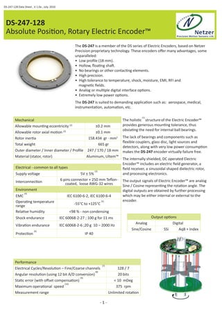
Absolute PosiƟ on, Rotary Electric Encoder™
The DS-247 is a member of the DS series of Electric Encoders, based on Netzer
Precision proprietary technology. These encoders off er many advantages, some
unparalleled:
• Low profi le (18 mm).
• Hollow, fl oaƟ ng shaŌ .
• No bearings or other contacƟ ng elements.
• High precision.
• High tolerance to temperature, shock, moisture, EMI, RFI and
magneƟ c fi elds.
• Analog or mulƟ ple digital interface opƟ ons.
• Extremely low power opƟ ons.
The DS-247 is suited to demanding applicaƟ on such as: aerospace, medical,
instrumentaƟ on, automaƟ on, etc.
Mechanical
Allowable mounƟ ng eccentricity (2) ±0.2 mm
Allowable rotor axial moƟ on (2) ±0.1 mm
Rotor inerƟ a 158.434 gr · mm2
Total weight 665 gr
Outer diameter / Inner diameter / Profi le 247 / 170 / 18 mm
Material (stator, rotor) Aluminum, Ultem™
Electrical - common to all types
Supply voltage 5V ± 5% (3)
InterconnecƟ on 6 pins connector + 250 mm Tefl on-coated,
loose AWG-32 wires
Environment
EMC (4) IEC 6100-6-2, IEC 6100-6-4
OperaƟ ng temperature
range -55°C to +125°C (5)
RelaƟ ve humidity <98 % - non condensing
Shock endurance IEC 60068-2-27 ; 100 g for 11 ms
VibraƟ on endurance IEC 60068-2-6 ;20 g 10 – 2000 Hz
ProtecƟ on (6) IP 40
The holisƟ c (1) structure of the Electric Encoder™
provides generous mounƟ ng tolerance, thus
obviaƟ ng the need for internal ball bearings.
The lack of bearings and components such as
fl exible couplers, glass disc, light sources and
detectors, along with very low power consumpƟ on
makes the DS-247 encoder virtually failure free.
The internally shielded, DC operated Electric
Encoder™ includes an electric fi eld generator, a
fi eld receiver, a sinusoidal shaped dielectric rotor,
and processing electronics.
The output signals of Electric Encoder™ are analog
Sine / Cosine represenƟ ng the rotaƟ on angle. The
digital outputs are obtained by further processing
which may be either internal or external to the
encoder.
Output opƟ ons
Analog Digital
Sine/Cosine SSi AqB + Index
Performance
Electrical Cycles/RevoluƟ on – Fine/Coarse channels (7) 128 / 7
Angular resoluƟ on (using 12 bit A/D conversion) (8) 20 bits
StaƟ c error (with off set compensaƟ on) (9) < 10 mDeg
Maximum operaƟ onal speed (10) 375 rpm
Measurement range Unlimited rotaƟ on
- 1 -
2. Sold & Serviced By:
Digital - SSi Interface (absolute posiƟ on) DS-247-128-Dn-0
Output signal parameters
Signal latency (11) ~250 μSec
Output code Binary
Serial output SSi Diff erenƟ al RS-422
Clock SSi Diff erenƟ al RS-422
Monofl op Ɵ me 25 μSec
Clock Frequency 0.5 ÷ 2.5 MHz
Maximum payload 21 bit
Electrical parameters
Current consumpƟ on ~ 180 mA
The naƟ ve output signals are analog Sine / Cosine of
the rotaƟ on angle. The digital outputs are obtained by
using external modules.
Synchronous Serial Interface (SSi) allows for serial
transmission of absolute posiƟ on data from the
Electric Encoder™ responding to controller clock
pulses. The Encoder and controller are linked by clock
and data diff erenƟ al signal lines.
Figure 1 illustrates the SSi Ɵ ming diagram used by
the Electric Encoder™ which is implemented in the
addiƟ onal digital electronics which provides advanced
calibraƟ on and monitoring opƟ ons using the NCP
(Netzer CommunicaƟ on Protocol) using factory
supplied soŌ ware tools.
+5V
Interpolator
1 (Grey)
2 (Blue)
3 (Yellow)
4 (Green)
5 (Black)
SC2SSi - Wires color code
# Name Color FuncƟ on
1 Clock + Grey SSi Clock
2 Clock - Blue
3 Data - Yellow 4 Data + Green SSi Data
5 GND Black Ground
6 +5V Red Power supply
- 2 -
Host System
SC2SSi
SSi-CLK / NCP RX
SSi-CLK / NCP RX
SSi-DATA / NCP TX
SSi-DATA / NCP TX
5V
5V
120 ɏ
6 (Red)
Gnd 1 (Black)
C/F 2 (Grey)
Sin 3 (Blue)
Vr 4 (Green)
Cos 5 (Yellow)
+5V 6 (Red)
Electric Encoder™
Gnd
A/D Electric Algorithm
angle
CalibraƟ on and analysis
over NCP
Electric Encoder SC2SSi external interpolator
Host system
Absolute
posiƟ on
ELECTROMATE
Toll Free Phone (877) SERVO98
Toll Free Fax (877) SERV099
www.electromate.com
sales@electromate.com
3. Sold & Serviced By:
Digital - SSi interface (absolute posiƟ on) DS-247-128-Dn-0
Figure - 1
T
n * T
n n - 1 1 0
n = total number of data bits.
T = clock period (sec) - user defi ned.
1/T = clock frequency 0.5 ÷ 2.5 MHz (user defi ned).
t1 = minimum Ɵ me required for the encoder to freeze data and preset the shiŌ
registers before receiving the fi rst rising edge to prompt the MSB
t2 = data transmission delay (increases with cable length)
t3 = required delay to refresh posiƟ on data between subsequent posiƟ on reads.
PosiƟ on calibraƟ on & signal analysis with SSi interface:
The Electric Encoder™ processing capabiliƟ es enable calibraƟ on, built-in tests
(BIT) and advanced setup, using the available soŌ ware tools, such as:
A. Simple calibraƟ on procedure using the SSi Explorer (CAA , Off sets , Zero
posiƟ on seƫ ng).
B. Field aid for validaƟ ng proper mechanical mounƟ ng.
- 3 -
1
t1
t3
2 3 n+1
Clock
t2 MSB
LSB
Data
a
t3
pulse train
Data transmission timing diagram
Synchronous serial data
ELECTROMATE
Toll Free Phone (877) SERVO98
Toll Free Fax (877) SERV099
www.electromate.com
sales@electromate.com
4. Sold & Serviced By:
ELECTROMATE
Digital - AqB + Index interface (incremental) DS-247-128-Cn-0
Output signal parameters
Signal latency (11) 250 μSec
Format Diff erenƟ al RS-422
Phase relaƟ onship with CW shaŌ rotaƟ on (as seen from top) A leads B
Index pulse width ½ A
Electrical parameters
Current consumpƟ on ~ 130 mA
SC2AqB - Wires color code
# Name Color FuncƟ on
1 GND Black Ground
2 +5V Red Supply voltage
3 A+ Yellow
Quadrature
outputs
4 A- Yellow/Black
5 B+ Blue
6 B- Blue / Black
7 Z+ Orange
Index
8 Z- White
- 4 -
Electric Encoder
A/D AqB
interpolaƟ on
Electric
angle
Toll Free Phone (877) SERVO98
Toll Free Fax (877) SERV099
www.electromate.com
sales@electromate.com
SC2AqB interpolator AqB + Index
5. Sold & Serviced By:
Analog - Sine/Cosine output (absolute posiƟ on) DS-247-128-00-0
Wires color code
# Name Color FuncƟ on
1 GND Black Ground
2 C/F Grey Coarse / Fine
3 Sine Blue Sine signal
4 Vr Green V reference
5 Cosine Yellow Cosine signal
6 +5V Red Power supply
Output signal parameters
Signal latency (11) 400 μSec
Fine-mode output noise (DC to 1kHz) (12) 200 μV (p-p)
Fine-mode output amplitude (13) 1V ± 10%
Coarse-mode output amplitude 1V ± 10%
Phase relaƟ onship (CW shaŌ rotaƟ on - seen
from top)
Sine leads Cosine
Signal bandwidth DC to 1 kHz
Coarse and Fine channels
The DS-247 has two operaƟ onal modes: a
Coarse-mode and a Fine-mode - equivalent
to two separate encoders in a common
housing. The modes are selectable by a
logic C/F command; logic “0” (0V to +0.5V)
selects the Coarse-mode, which has 7
Electrical Cycle/RevoluƟ on (EC/R) while
logic ”1” (+3V to +5V) selects the Fine-mode
which has 128 EC/R. The switching
Ɵ me is less than 1 ms.
The Coarse-mode outputs need to be read
only upon system iniƟ aƟ on aŌ er which
the encoder is permanently switched
to the Fine mode. Coarse and Fine sine/
cosine pairs are used to calculate the iniƟ al
absolute posiƟ on, from that point tracking
the Fine-channel outputs provides the
absolute mechanical rotaƟ on angle with the
specifi ed accuracy and resoluƟ on.
All output signals are referenced to an
internally generated voltage Vr (~2.25V)
Electrical parameters
Output resistance <1 Ω
Current consumpƟ on ~ 10 mA (14)
Absolute PosiƟƟ on calculaƟƟ on:
The analog Sine /Cosine outputs convey the electric angle of the Coarse or Fine signals. The
absolute mechanical angle is computed by digiƟ zing the analog signals and applying factory-supplied
algorithms. Please refer to AN-02 and AN-03 .
- 5 -
Electric Encoder
A/D Electric Algorithm
angle
Host system
Absolute
posiƟ on
ELECTROMATE
Toll Free Phone (877) SERVO98
Toll Free Fax (877) SERV099
www.electromate.com
sales@electromate.com
6. Sold & Serviced By:
Notes
1. The output signals are generated by the whole area of the rotor - see AN-01.
2. Accuracy may degrade depending on mounƟ ng tolerances and the Sine/Cosine amplitudes
may exceed the A/D conversion range -see AN-02
3. The encoder includes an internal 4.5V LDO voltage regulator.
4. Standard DS encoders are insensiƟ ve to ESD, stray magneƟ c and capaciƟ ve coupling
from the host system current consumpƟ on. However it is advisable to allow a discharge path
of no more than several tens of kΩ between the machine shaŌ and the electronic’s ground,
not leaving it electrically fl oaƟ ng.
5. Consult factory.
6. For higher ingress protecƟ on the encoder should be mounted inside a sealed enclosure.
7. The number of electrical sine/cosine cycles generated in one mechanical rotaƟ on.
8. The angular resoluƟ on is determined by the raƟ o of the Fine - channel amplitude and the
encoder inherent noise – see AN-05.
9. Not including dynamic error. For higher staƟ c accuracy consult factory.
10. Determined by the Fine-channel EC/Rs and the internal low pass fi lters, for higher rotaƟ on
speed consult factory.
11. An inherent signal delay inversely proporƟ onal to the internal fi lter’s cut-off frequency (1 kHz,
3rd order Bessel) and resulƟ ng in a dynamic error proporƟ onal to the rotaƟ on
speed - see AN-05
12. For measuring the noise and validaƟ ng the interconnecƟ on see AN-02.
13. With the rotor at its nominal axial posiƟ on - see AN-02.
14. For a micro-power version with current consumpƟ on down to 50 μA @ 3V consult factory.
ResoluƟ on In bits Steps /360° mDeg /step Arc-sec /step mRad /step
17 131,072 2.7466 9.8877 0.0479
18 262,144 1.3733 4.9438 0.024
19 524,288 0.6866 2.4719 0.012
20 (DS-247) 1,048,576 0.3433 1.236 0.006
21 2,097,152 0.1717 0.618 0.003
22 4,194,304 0.0858 0.309 0.0015
Related documents:
DS-247 Mechanical InstallaƟ on Guide
- 6 -
ELECTROMATE
Toll Free Phone (877) SERVO98
Toll Free Fax (877) SERV099
www.electromate.com
sales@electromate.com
7. 250 mm
250 mm
250 mm
- 7 -
DS
Product line
OD
EC/R
Outputs
0 - Analog: Sine/Cosine
C - Digital : AqB + index (external module SC2AqB)
D - Digital : SSi (external module SC2SSi03)
Binary
ResoluƟ on
CPR
32,768
16,384
4,096
8,192
65,536
Toll Free Phone (877) SERVO98
Toll Free Fax (877) SERV099
131,072
ELECTROMATE
www.electromate.com
sales@electromate.com
524,288
Bit 12 13 14 15 16 17 18 19 20
Code A B C D E F G H I
DS - 247- 128 - DI - C
Connector
Decimal
ResoluƟ on
CPR
64,000
128,000
32,000
16,000
8,000
512,000
Bit 13 14 15 16 17 18 19 20
Code K L M N O P Q R
Ordering
262,144
256,000
SC2SSi external module
CAT # SC2SSi-03 [42 x 13 mm] Default
CAT # SC2SSi-05 [30 x 13 mm]
AWG32 Teflon isolated
250 mm
AWG32 Teflon isolated
AWG32 Teflon isolated
SC2AqB external module
CAT # SC2AqB-00 [25 x 20 mm]
AWG32 Teflon isolated
250 mm
AWG32 Teflon isolated
Analog Sin/Cosine
Digital SSi
Digital AqB
1,048,576
1,0124,000
Sold & Serviced By: