1. TH Analog
Data Sheet
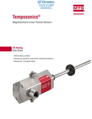
Temposonics®
Magnetostrictive Linear Position Sensors
– ATEX & IECEx certified
– Continuous operation under harsh industrial conditions
– Flameproof / Increased safety
ELECTROMATE
Toll Free Phone (877) SERVO98
Toll Free Fax (877) SERV099
www.electromate.com
sales@electromate.com
Sold & Serviced By:
2. Magnet field
of current pulse
Magnet field
of position magnet
Mechanical
strain pulse
Movable
position magnet
Magnetostrictive
sensing element
(waveguide)
Current
interrogation
pulse
Strain (torsion)
pulse converter
Temposonics®
TH Analog
Data Sheet
MEASURING TECHNOLOGY
For position measurement, the absolute, linear Temposonics®
position
sensors make use of the properties offered by the specially designed
magnetostrictive waveguide. Inside the sensor a torsional strain pulse
is induced in the waveguide by momentary interaction of two magnetic
fields. The interaction between these two magnetic fields produces
a strain pulse, which is detected by the electronics at the head of the
sensor. One field is produced by a moving position magnet, which
travels along the sensor rod with the waveguide inside. The other field
is generated by a current pulse applied to the waveguide. The position
of the moving magnet is determined precisely by measuring the time
elapsed between the application of the current pulse and the arrival
of the strain pulse at the sensor head. The result is a reliable position
measurement with high accuracy and repeatability.
Fig. 1: Time-based magnetostrictive position sensing principle
TH SENSOR
The TH sensor is extremely robust and ideal for continuous operation
under harsh industrial conditions. T-Series sensors are ATEX and IECEx
certified for hazardous areas in zone 0/1, zone 1, zone 2, zone 21 and
zone 22 (flameproof/increased safety).
The T-Series is offered in a standard 10 mm (0.39 in.) rod in lengths
from 25…7600 mm (1…300 in.) The sensor rod is capable of with-
standing high pressures such as those found in hydraulic cylinders.
Furthermore the sensor is also suitable for petro chemical plants and
caustic environments. The sensor head contains the active signal condi-
tioning and a complete integrated electronics interface.
Certification
Version D
Flameproof housing with flameproof connection chamber:
IBExU 14 ATEX 1232X
IECEx IBE 14.0062X
II 1/2G Ex db IIC T4 Ga/Gb
II 1G/2D Ex tb IIIC T130°C Ga/Db
Version E
Flameproof housing with increased safety connection chamber:
IBExU 14 ATEX 1232X
IECEx IBE 14.0062X
II 1/2G Ex db e IIC T4 Ga/Gb
II 1G/2D Ex tb IIIC T130°C Ga/Db
Version N
No hazardous rating:
IP66, IP67, IP68, IP69K, NEMA 4X
ELECTROMATE
Toll Free Phone (877) SERVO98
Toll Free Fax (877) SERV099
www.electromate.com
sales@electromate.com
Sold & Serviced By:
3. Temposonics®
TH Analog
Data Sheet
TECHNICAL DATA
Output
Current 4(0)…20 mA, 20…4(0) mA (minimum/maximum load 0/500 Ω)
Measured value Position
Measurement parameters
Resolution 16 bit; 0.0015 % (minimum 1 µm)
Cycle time 0.5 ms up to 1200 mm, 1.0 ms up to 2400 mm, 2.0 ms up to 4800 mm,
5.0 ms up to 7600 mm stroke length
Linearity 1
< ±0.01 % F.S. (minimum ±50 µm)
Repeatability < ±0.001 % F.S. (minimum ±2.5 µm)
Hysteresis < 4 µm
Temperature coefficient < 30 ppm / °C
Operating conditions
Operating temperature −40…+75 °C (−40…+167 °F)
Humidity 90 % rel. humidity, no condensation
Ingress protection Version D and E: IP66/IP67
Version N: IP66, IP67, IP68, IP69K, NEMA 4X, depending on cable gland
Shock test 100 g (single hit) / IEC standard 60068-2-27
Vibration test 15 g / 10…2000 Hz, excluding resonate frequencies, IEC standard 60068-2-6
EMC test Electromagnetic emission according to IEC/EN 55011 +A1 Class B
Electromagnetic immunity according to IEC/EN 61000-6-2
Magnet movement velocity Any
Design/Material
Sensor electronics housing 1.4305 (AISI 303) option 1.4404 (AISI 316L)
Sensor rod 1.4306 (AISI 304L) option 1.4404 (AISI 316L)
Stroke length 25…7600 mm (1…300 in.)
Operating pressure 350 bar static (5000 psi static)
Mechanical mounting
Mounting position Any orientation
Mounting instruction Please consult the technical drawings and the operation manual
(document number: 551513)
Electrical connection
Connection type T-Series terminal
Operating voltage +24 VDC (−15 / +20 %)
Ripple ≤ 0.28 Vpp
Current consumption 100 mA typical
Dielectric strength 700 VDC (DC ground to machine ground)
Polarity protection Up to −30 VDC
Overvoltage protection Up to 36 VDC
1/ With position magnet # 201 542-2
ELECTROMATE
Toll Free Phone (877) SERVO98
Toll Free Fax (877) SERV099
www.electromate.com
sales@electromate.com
Sold & Serviced By:
4. 132.5
(5.22) 2.5
(0.1)
83.8
(3.29)
77
(3.03)
55
(2.17)
51
(2)
Null zone Stroke length
25…7600
(1…300)
Dead zone
63.5 (2.5) / 66 (2.6)*
Refer to “Table 1” for
“Flange threads”
* > 5000 (197) stroke length
Sensor electronics housing
Magnet
Ø10±0.13
(Ø0.39±0.001)
Version D
Version E & N
Null zone Dead zoneSensor electronics housing
83.8
(3.29)
55
(2.17)
73
(2.87)
Sensor electronics housing
112.5
(4.43)
51 63.5 (2.5) /
66 (2.6)*(2)
Null zone Stroke length
25…7600
(1…300)
Stroke length
Dead zone
Refer to “Table 1” for
“Flange threads”
* > 5000 (197) stroke length
Ø10±0.13
(Ø0.39±0.001)
Magnet
Version D
83.8
(3.29)
132.5
(5.22)
55
(2.17)
51
(2)
Null zone Dead zoneSensor electronics housing
83.8
(3.29)
55
(2.17)
73
(2.87)
77
(3.03)
Sensor electronics housing
112.5
(4.43)
51 63.5 (2.5) /
66 (2.6)*(2)
Null zone Stroke length
25…7600
(1…300)
Stroke length
25…7600
(1…300)
Dead zone
Refer to “Table 1” for
“Flange threads”
Refer to “Table 1” for
“Flange threads”
* > 5000 (197) stroke length
* > 5000 (197) stroke length
63.5 (2.5) /
66 (2.6)*
Ø10±0.13
(Ø0.39±0.001)
Magnet
Magnet
Ø10±0.13
(Ø0.39±0.001)
With flat-faced flange
Temposonics®
TH Analog
Data Sheet
TECHNICAL DRAWINGS
(4.43)
2.5
(0.1)
83.8
(3.29)
73
(2.87)
55
(2.17)
51
(2)
Null zone
Ø10±0.13
(Ø0.39±0.001)
Stroke length
25…7600
(1…300)
Dead zone
Refer to “Table 1” for
“Flange threads”
63.5 (2.5) / 66 (2.6)*
* > 5000 (197) stroke length
Sensor electronics housing
112.5
Magnet
Version E & N
Controlling design dimensions are in millimeters and measurements in ( ) are in inches
Unless otherwise stated, apply to the general tolerances according to DIN ISO 2768-m
With raised-face flange
ELECTROMATE
Toll Free Phone (877) SERVO98
Toll Free Fax (877) SERV099
www.electromate.com
sales@electromate.com
Sold & Serviced By:
5. Magnet
18 (0.7)
Side connection C01 / N01 / NF1 (with adapter) / M01 (without adapter)
Temposonics®
TH Analog
Data Sheet
Flange type Description Flange threads
F
Flange with flat-face
1.4404 (AISI 316L)
¾"-16 UNF-3A
G
Flange with raised-face
1.4404 (AISI 316L)
¾"-16 UNF-3A
M
Flange with flat-face
1.4305 (AISI 303)
M18×1.5−6g
N
Flange with raised-face
1.4305 (AISI 303)
M18×1.5−6g
S
Flange with flat-face
1.4305 (AISI 303)
¾"-16 UNF-3A
T
Flange with raised-face
1.4305 (AISI 303)
¾"-16 UNF-3A
W
Flange with flat-face
1.4404 (AISI 316L)
M18×1.5−6g
Table 1: Model TH flange type references
Top connectionTop connection Connection length
Magnet
18
(0.7)
Top connection C10 / N10 (with adapter) / M10 (without adapter)
Controlling design dimensions are in millimeters and measurements in ( ) are in inches
Unless otherwise stated, apply to the general tolerances according to DIN ISO 2768-m
CONNECTION OPTIONS
Connector on 6 different
positions at 60° each
Sensor with adapter
Sensor with adapter
ELECTROMATE
Toll Free Phone (877) SERVO98
Toll Free Fax (877) SERV099
www.electromate.com
sales@electromate.com
Sold & Serviced By:
6. Zone 1 Zone 0
Magnet
Zone 1 Zone 0
Magnet
Temposonics®
TH Analog
Data Sheet
Version D –
Flameproof housing with flameproof connection chamber ATEX / IECEx
Ex db / Ex tb
ZONE DIVISION
Version E –
Flameproof housing with increased safety connection chamber ATEX / IECEx
Ex db e / Ex tb
NOTICE
Seal sensor according to ingress protection IP67 between zone 0
and zone 1.
ELECTROMATE
Toll Free Phone (877) SERVO98
Toll Free Fax (877) SERV099
www.electromate.com
sales@electromate.com
Sold & Serviced By:
7. Temposonics®
TH Analog
Data Sheet
CONNECTOR WIRING
Suitable for connection types: C01, C10, M01, M10, N01, N10 Pin Description
1 Output 1
2 DC Ground
3 Output 2
4 DC Ground
5 +24 VDC (−15 / +20 %)
6 DC Ground (0 V)
7 PE – Protective Earth Ground
Model TH (version E & N) rod-style sensor wiring diagram (1.5 mm2
conductor)
External ground lug
External ground lug
External ground lug
External ground lug
External ground lug
External ground lug
Suitable for connection types: C01, C10, N01, N10 Pin Description
1 Output 1
2 DC Ground
3 Output 2
4 DC Ground
5 +24 VDC (−15 / +20 %)
6 DC Ground (0 V)
7 PE – Protective Earth Ground
Model TH (version D) rod-style sensor wiring diagram (2.5 mm2
conductor)
Suitable for connection type: NF1 Pin Description
1 Output
2 DC Ground
3 Output 2
4 +24 VDC (−15 / +20 %)
5 DC Ground (0 V)
6 PE – Protective Earth Ground
Model TH (version E & N) rod-style sensor wiring diagram (2.5 mm2
conductor)
External ground lug
External ground lug
External ground lug
ELECTROMATE
Toll Free Phone (877) SERVO98
Toll Free Fax (877) SERV099
www.electromate.com
sales@electromate.com
Sold & Serviced By:
8. Temposonics®
TH Analog
Data Sheet
Position magnets
Ø 32.8
(Ø 1.29)
Ø 23.8
(Ø 0.94)
Ø 13.5
(Ø 0.53)
Ø 4.3
(Ø 0.17)
7.9
(0.31)
Ø 25.4
(Ø 1)
Ø 13.5
(Ø 0.53) 7.9
(0.31)
Ø 32.8
(Ø 1.29)
Ø 23.8
(Ø 0.94)
Ø 13.5
(Ø 0.53)
Ø 4.3
(Ø 0.17)
60°
140°
3
(0.12)
7.9
(0.31)
Standard ring magnet
Part no. 201 542-2
Material: PA ferrite GF20
Weight: Ca. 14 g
Operating temperature:
−40…+105 °C (−40…+221 °F)
Surface pressure: Max. 40 N/mm2
Fastening torque for M4 screws:
Max. 1 Nm
Ring magnet OD25,4
Part no. 400 533
Material: PA ferrite
Weight: Ca. 10 g
Operating temperature:
−40…+105 °C (−40…+221 °F)
Surface pressure: Max. 40 N/mm2
U-magnet OD33
Part no. 251 416-2
Material: PA ferrite GF20
Weight: Ca. 11 g
Operating temperature:
−40…+105 °C (−40…+221 °F)
Surface pressure: Max. 40 N/mm2
Fastening torque for M4 screws:
Max. 1 Nm
Magnet floats 2
Ø 18
(Ø 0.7)
Ø 47
(Ø 1.85)
77
(3.01)
Ø 18
(Ø 0.7)
57
(2.22)
Ø 59
(Ø 2.32)
Ø 18
(Ø 0.7)
36
(1.4)
Ø 41
(Ø 1.61)
Ø 18
(Ø 0.7)
Ø 89
(Ø 3.5)91
(3.57)
Magnet float
Part no. 251 981-2
Pressure: 29.3 bar (425 psi)
Operating temperature:
−40…125 °C (−40…257 °F)
Magnet offset: No
Specific gravity: 0.67
Material: Stainless steel
Weight offset: Yes
Magnet float
Part no. 251 387-2
Pressure: 22.4 bar (325 psi)
Operating temperature:
−40…125 °C (−40…257 °F)
Magnet offset: No
Specific gravity: 0.48
Material: Stainless steel
Weight offset: Yes
Magnet float
Part no. 200 938-2
Pressure: 8.6 bar (125 psi)
Operating temperature:
−40…125 °C (−40…257 °F)
Magnet offset: No
Specific gravity: 0.74
Material: Stainless steel
Weight offset: Yes
Magnet float
Part no. 251 469-2
Pressure: 29.3 bar (425 psi)
Operating temperature:
−40…125 °C (−40…257 °F)
Magnet offset: No
Specific gravity: 0.45
Material: Stainless steel
Weight offset: Yes
2/ – Be sure that the float specific gravity is at least 0.05 less than that of the measured
liquid as a safety margin at ambient temperature.
– For interface measurement: A minimum of 0.05 specific gravity differential is required
between the upper and lower liquids.
– When the magnet is not shown, the magnet is positioned at the center line of float.
– An offset weight is installed in the float to bias or tilt the float installed on the sensor
tube. So the float remains in contact with the sensor tube at all times and guarantees
permanent potential equalization of the float. The offset is required for installations that
must conform to ATEX standards.
Controlling design dimensions are in millimeters and measurements in ( ) are in inches
FREQUENTLY ORDERED ACCESSORIES – Additional options available in our Accessories Guide 551444
ELECTROMATE
Toll Free Phone (877) SERVO98
Toll Free Fax (877) SERV099
www.electromate.com
sales@electromate.com
Sold & Serviced By:
9. Temposonics®
TH Analog
Data Sheet
Magnet floats 3
Standard interface floats 3
Ø 18
(0.7)
50
(1.96)
Ø 47
(1.83)
54
(2.11)
Ø 18
(Ø 0.7)
31
(1.22)
27
(1.06)
Ø 47
(Ø 1.83)
Ø 18
(Ø 0.7)
Ø 47
(Ø 1.85)
77
(3.01)
Ø 18
(Ø 0.7)
Ø 47
(Ø 1.85)
77
(3.01)
Magnet float 4
Part no. 201 605-2
Pressure: 4 bar (60 psi)
Operating temperature:
−40…125 °C (−40…257 °F)
Magnet offset: Yes
Specific gravity: 0.6
Material: Stainless steel
Weight offset: Yes
Magnet float 4
Part no. 201 606-2
Pressure: 4 bar (60 psi)
Operating temperature:
−40…125 °C (−40…257 °F)
Magnet offset: Yes
Specific gravity: 0.93
Material: Stainless steel
Weight offset: Yes
Magnet float
Part no. 251 982-2
Pressure: 29.3 bar (425 psi)
Operating temperature:
−40…125 °C (−40…257 °F)
Magnet offset: No
Specific gravity: 0.90…0.96
Material: Stainless steel
Weight offset: Yes
Magnet float
Part no. 251 983-2
Pressure: 29.3 bar (425 psi)
Operating temperature:
−40…125 °C (−40…257 °F)
Magnet offset: No
Specific gravity: 1.03…1.10
Material: Stainless steel
Weight offset: Yes
Collar Programming tools
Ø 27
(Ø 1.06) Ø 10
(Ø 0.39)
5
(0.2)
8-32 threads
4
(0.16)
8
(0.31)
9
(0.35)
Collar
Part no. 560 777
Material:
Stainless steel 1.4301(AISI 304)
Weight: Ca. 30 g
Hex key 7⁄64 required
Analog hand programmer
Part no. 253 124
Easy teach-in-setups of stroke length
and direction on desired zero/span
positions. For the first output.
Programming kit
Part no. EU: 253 134-1
Part no. US: 253 309-1
Kit includes:
Interface converter box,
power supply, cable
Software is available at:
www.mtssensors.com
Analog cabinet programmer
Part no. 253 408
Features snap-in mounting on stan-
dard 35 mm DIN rail. This program-
mer can be permanently mounted
in a control cabinet and includes a
program/run switch. For the first
output.
3/ – Be sure that the float specific gravity is at least 0.05 less than that of the measured
liquid as a safety margin at ambient temperature.
– For interface measurement: A minimum of 0.05 specific gravity differential is required
between the upper and lower liquids.
– When the magnet is not shown, the magnet is positioned at the center line of float.
– An offset weight is installed in the float to bias or tilt the float installed on the sensor
tube. So the float remains in contact with the sensor tube at all times and guarantees
permanent potential equalization of the float. The offset is required for installations that
must conform to ATEX standards.
4/ Standard float that can be expedited.
Controlling design dimensions are in millimeters and measurements in ( ) are in inches
ELECTROMATE
Toll Free Phone (877) SERVO98
Toll Free Fax (877) SERV099
www.electromate.com
sales@electromate.com
Sold & Serviced By:
10. Standard stroke length (mm)*
Stroke length Ordering steps
25 … 500 mm 5 mm
500 … 750 mm 10 mm
750…1000 mm 25 mm
1000…2500 mm 50 mm
2500…5000 mm 100 mm
5000…7600 mm 250 mm
Standard stroke length (in.)*
Stroke length Ordering steps
1 … 20 in. 0.2 in.
20 … 30 in. 0.4 in.
30 … 40 in. 1.0 in.
40…100 in. 2.0 in.
100…200 in. 4.0 in.
200…300 in. 10.0 in.
Temposonics®
TH Analog
Data Sheet
T H 1 N N
a b c d e f g h i
a Sensor model
T H Hydraulic rod style
b Design
Model TH rod-style sensor with housing 1.4305 (AISI 303)
(hydraulic rod style, material 1.4306 (AISI 304L))
M Flange with flat-face (M18×1.5−6g)
N Flange with raised-face (M18×1.5−6g)
S Flange with flat-face (¾"-16 UNF-3A)
T Flange with raised-face (¾"-16 UNF-3A)
Model TH rod-style sensor with housing 1.4404 (AISI 316L)
(hydraulic rod style, material 1.4404 (AISI 316L))
F Flange with flat-face (¾"-16 UNF-3A)
G Flange with raised-face (¾"-16 UNF-3A)
W Flange with flat-face (M18×1.5−6g)
e Operating voltage
1 +24 VDC (−15 / +20 %)
f Version
D Ex db and Ex tb
E Ex db e and Ex tb
N No hazardous rating
g Functional safety type
N Not approved
h Additional option type
N None
i Output
1 output with 1 magnet
Output 1 (position magnet 1)
A 0 1 4…20 mA
A 1 1 20…4 mA
A 2 1 0…20 mA
A 3 1 20…0 mA
2 outputs with 1 magnet
Output 1 (position magnet 1) + output 2 (position magnet 1)
A 0 3 4…20 mA 20…4 mA
2 outputs with 2 magnets
Output 1 (position magnet 1) + output 2 (position magnet 2)
A 0 2 4…20 mA 4…20 mA
A 1 2 20…4 mA 20…4 mA
A 2 2 0…20 mA 0…20 mA
A 3 2 20…0 mA 20…0 mA
ORDER CODE
c Stroke length
X X X X M 25…7600 mm
X X X X U 1…300 in.
d Connection type
C 0 1 Side connection with thread ½" NPT (version D & E & N)
C 1 0 Top connection with thread ½" NPT (version D & E & N)
M 0 1 Side connection with thread M16×1.5 (version E & N)
M 1 0 Top connection with thread M16×1.5 (version E & N)
N 0 1 Side connection with thread M20×1.5
(version D & E& N)
N 1 0 Top connection with thread M20×1.5 (version D & E & N)
N F 1 Side connection with thread M20×1.5 (version E & N)
.
DELIVERY
Sensor Accessories have to be ordered
separately
Operation manuals & software are available at:
www.mtssensors.com
1 2 3 4 5 6 7 8 9 10 11 12 13 14 15 16 17 18
*/ Non Standard stroke lengths are available; must be encoded in 5 mm / 0.1 in. increments
ELECTROMATE
Toll Free Phone (877) SERVO98
Toll Free Fax (877) SERV099
www.electromate.com
sales@electromate.com
Sold & Serviced By: