Elevate Developer Efficiency & build GenAI Application with Amazon Q
Inertia dynamic motor brake specsheet
1. C-Face Power-Off Brakes
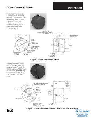
Single C-Face, Power-Off Brake
Single C-Face, Power-Off Brake With Cast Iron Housing
25°
5.875 Dia. B.C.
6.81 Dia.
1/2 REF
Brake
Release
Lever
3
/8 – 16 x 21
/2
S.H.C.S.
Supplied
(2) Places
Optional Lead Egress
(2) 31/64 Dia. Holes
180° Apart on a 213
/16 Radius
.25 Dia.
1.06
(1
/2 NPT)
4.503
4.501
Dia.
.195
.185
5.11 3.00
Clearance
Required
to
Remove
Cover
2.62
1/2 – 14 NPT
5/8, 3/4, & 7/8 Bore Sizes Available
Keyway for 3/16 Square Key
45°
2.81 Radius
.38 Dia. Lead Holes
Located as shown
180° apart
5
/8, 3
/4 & 7
/8 Bore Sizes
Available Keyway
for 3
/16 Square Key
Brake
Release Lever
Optional External
Lead Outlet
1
/2 – 14 NPT
4.503
4.501
Dia.
3.853.44
45°
The Inertia Dynamics Single
C-Face Power-Off Brakes are
designed to decelerate or hold
inertial loads when the power
is turned off. The single
C-Face mounts on the fan or
nondriven end of a motor.
Brakes are available from
3 lb.-ft. to 15 lb.-ft.
The Inertia Dynamics single
C-Face Power-Off Brake with
cast iron housing is made for
applications involving corrosive
environments. The heavy-duty
housing also includes o-ring
seals to create a dust-tight
brake.
25°
1.19 to Pivot Point
of Release Lever
.31 Set DIM.
for Hub
4.56
6.62 Dia.
1.25
.26 Dia.
2.94
Clearance Required
to Remove Cover
.25
.75 to Lead
Outlet
Qty. (2) 3
/8 – 16 x 2.00
Mounting Bolts Located as Shown
on a 5.875 Dia. B.C.
6.34 Dia.
Motor Brakes
62 ELECTROMATE
Toll Free Phone (877) SERVO98
Toll Free Fax (877) SERV099
www.electromate.com
sales@electromate.com
Sold & Serviced By:
2. 63
C-Face Power-Off Brakes
Double C-Face, Power-Off Brake
The Inertia Dynamics Motor
Brake is available in a single
C-Face Explosion-Proof (XP)
enclosure. The housing is
designed to comply with
NEC outlines for Class I,
Group D, and Class II,
Groups F&G.
The Inertia Dynamics Double
C-Face Brake is designed for
use as a coupler between
standard C-Face motors and
C-Face gear reducers. An
optional foot mount kit is
also available with this unit.
5
/8, 3
/4, & 7
/8 Bore Sizes
Available – Keyway for 3
/16
Square Key
3
/8 – 16 x 3
/4
Hex Head
Bolt
(4) Supplied
Conduit Box
Optional
Supplied Only
When Specified
3.72
3.75
Clearance Required
to Remove Cover
Two External Lead
Holes – 1
/2 N.P.T.
Clearance
Required to
Remove
Cover
Assembly
3
/8 – 16 Tap x
.56 Deep on a
5.875 Dia. B.C.
8.04
6.62
3.94
1.62 1.19
7.442.88
2.44
.75
X
.25
.12
2.00
3
/16 Key
x 1.25
4.500
4.497
Dia. 4.501
4.503
Dia. 7.88 Dia.
3.84
45°
4 Holes
.41 Dia.
5
/8 & 7
/8 Shaft
Sizes Available
5
/8 & 7
/8 Bore Sizes
Available Keyway for 3
/16
Square Key
4.29
8.00
TYP.
.195
.185
6.42
Brake
Release
Lever
4.503
4.501
Dia.
6.75 Dia. Ref.
.60 5.875 Dia. B.C.
45°
.56
4.41
2.25
Optional Conduit Box
5.875
Dia.B.C.
Single C-Face, Explosion-Proof Power-Off Brake
Motor Brakes
ELECTROMATE
Toll Free Phone (877) SERVO98
Toll Free Fax (877) SERV099
www.electromate.com
sales@electromate.com
Sold & Serviced By:
3. 60
Ordering Information
PART NUMBERING SYSTEM
A B C D E F G H I
LETTER TYPE
A Add on
Brake
F Single
C-Face
(F Brake)
M Double
C-Face
w/o Feet
N Double
C-Face
w/ Feet
How To Order
Read the product guide before determining the brake part number.
A. Select the brake type from the product guide.
B. For all motor brakes, select 5.
C. Select the number of discs: 3 lb.-ft. = 1 disc, 6 lb.-ft. = 2 discs, 10 lb.-ft. = 2
discs, 15 lb.-ft. = 3 discs.
D.Select the bore diameter.
E. Select the enclosure type.
F. Select the required brake torque.
G.Select the lead outlet.
H.Select the required brake coil voltage (VAC).
I. For all motor brakes, select M.
Example
Single C-Face brake, 5
/8Љ bore, standard enclosure, 6 lb.-ft., no outlet, 230/460
VAC, 60Hz, F52A0604M.
DIGIT SERIES
5 50 Series
DIGIT NO. OF
DISCS
1 1 Disc
2 2 Discs
3 3 Discs
LETTER HUB
BORE
A 5
/8Љ
B 3
/4Љ
C 7
/8Љ
Z Special
DIGIT ENCLOSURE
TYPE
0 Standard
1 SXT –
Cast Iron
3 Special
4 XP –
Internal
5 XP –
External
DIGIT BRAKE
TORQUE
3 3 lb.-ft.
6 6 lb.-ft.
7 10 lb.-ft.
8 15 lb.-ft.
DIGIT LEAD
OUTLET
0 No Outlet
1 Lead
Outlet
Thru
Head
w/o Leads
2 Lead
Outlet
Thru
Head
w/ Leads
3 Lead
Outlet
Thru
Head
w/ Leads
& C/B
COIL
DIGIT VOLTAGE
(VAC)
Stamp N/P
Coil Voltage
(VAC LO/VAC HI/Hz)
1 115/230/60
2 200/400/60
3 230/460/60
4 230/460/60
5 287/575/60
8 115/230/50
9 220/440/50
Stamp N/P
Blank-Suit For:
1 104/208/50
2 208/416/60
3 220/440/50
4 190/380/50
5 275-300/
550-600/60
9 230/460/50
LETTER CONFIG-
URATION
M Original
Config-
uration
Motor Brakes
ELECTROMATE
Toll Free Phone (877) SERVO98
Toll Free Fax (877) SERV099
www.electromate.com
sales@electromate.com
Sold & Serviced By:
4. 61
General Information
Spring Applied —
Power-Off Operation
Inertia Dynamics AC-style, spring
applied motor brakes are designed to
decelerate or park inertial loads when
the voltage is turned off, either inten-
tionally or accidentally, as in the case
of power failure. The friction disc with
the hub is coupled to the motor shaft
to be braked but is capable of moving
axially. When power is off, a spring
force clamps the friction disc between
a pressure plate and a stationary
plate, hence retarding motion. When
an AC voltage is applied, the solenoid
creates a magnetic force which pulls a
lever arm through a linkage mecha-
nism and releases the friction disk.
This allows the hub and motor shaft
to turn freely.
Application
The motor brakes are commonly used
as parking brakes to hold a load in
place or as stopping brakes to dynam-
ically decelerate a load. Applications
include:
▫ Material Handling
▫ Food Processing
▫ Machine Tools
Features
▫ External Manual Release Lever
▫ Totally Enclosed Construction
▫ Torque adjustable from full rated
torque down to 50%
▫ Single phase AC coils provide fast
engagement and release times and
easy wiring
Mounting
Two styles are available: the single
C-Face brake and the double C-Face
brake. The single C-Face mounts on
the fan end or non-driven end of a
motor. The C-Face brake is inter-
changeable with existing brakes and
can be used on motors that are modi-
fied to accept a brake. The double
C-Face brake can be used as a cou-
pler between standard C-Face motors
and C-Face gear reducers. All motor
brakes are interchangeable with com-
petitive motor brakes.
Add-On Brakes
A complete kit is available to convert a
standard Reliance Electric TEFC motor
to a brake motor. The frame size must
be 56 or 140. The kit is not available
for special enclosures such as wash-
down or explosion proof.
Selection Procedure
1. To make an accurate brake selection, first determine the
motor frame size, shaft size, hp, and RPM where the
brake will be mounted.
2. Use chart on the right for static brake torque selection.
Note that chart selections are based on a 1.4 service fac-
tor and increased to the next highest standard brake
torque rating. To select a brake using a different service
factor, use the formula below to determine the required
brake static torque. Once your torque requirement
has been determined, select a brake with at least
that capacity.
3. Consult Part Number chart on page 60 for appropriate
part number. Brake voltage should be matched with
motor voltage rating.
Static Brake Torque Ratings* (Lb.- Ft.) Selection
Motor Brake Coil Current
MOTOR SPEED (RPM)
HP 750 900 1200 1500 1800 3000 3600
1
/4 3 3 3 3 3 3 3
1
/3 6 3 3 3 3 3 3
1
/2 6 6 6 3 3 3 3
3
/4 10 10 6 6 6 3 3
1 10 10 10 6 6 3 3
11
/2 15 15 10 10 10 6 6
2 – – 15 10 10 6 6
3 – – – 15 15 10 10
5 – – – – – 15 15
*Selections based on 1.4 service factor and increased to next highest standard brake torque
rating.
T =
HP x 5252
x SF
RPM
T = Brake Static Torque (FT.–LBS.)
HP = Motor Horsepower
SF = Service Factor Desired
RPM = Motor Speed
BRAKE CURRENT
(AMPS)VOLTS
HZ
HOLDING INRUSH
(VAC)
115/230 .54/.27 4.8/2.4
200/400 .31/.15 2.8/1.4
208/416 60 .32/.16 2.6/1.3
230/460 .27/.13 2.6/1.3
287/575 .22/.11 2.1/1.05
104/208 .5/.25 5.3/2.65
115/230 .5/.25 5.4/2.7
190/380 50 .26/.13 3.0/1.5
220/440 .3/.15 3.3/1.65
230/460 .26/.13 2.7/1.36
Motor Brakes
ELECTROMATE
Toll Free Phone (877) SERVO98
Toll Free Fax (877) SERV099
www.electromate.com
sales@electromate.com
Sold & Serviced By: