Ceramic cavity resonator
•
0 likes•141 views

perform shrink fit calculations for a ceramic dielectric microwave cavity resonator

Recommended
Recommended
More Related Content
Similar to Ceramic cavity resonator
Similar to Ceramic cavity resonator (20)
More from Don Blanchet
More from Don Blanchet (20)
Recently uploaded
Recently uploaded (20)
Ceramic cavity resonator
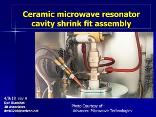
- 1. Ceramic microwave resonator cavity shrink fit assembly 4/9/18 rev A Don Blanchet 3B Associates dwb3298@verizon.net Photo Courtesy of: Advanced Microwave Technologies
- 2. Component Assembly Aluminum housing Cylindrical Ceramic resonator puck Heat housing in fixture Insert puck using alignment fixture Cool to room temperature Shrink fit established – Puck in compression – Housing in radial tension
- 3. HOUSING ID Expansion Δ𝑙 = 𝛼𝐿Δ𝑇 = 2.3𝑒 − 05 𝑥 1 𝑥 50 50C rise = .00115 inch 100C rise = .00230 inch 200C rise = .00460 inch 250C rise = .00575 inch Aluminum Melting point 593 C
- 4. Assembly measurements example for randomly selected parts : Housing ID = 0.998 at room temp Puck OD = 1.001 at room temp Heat housing to 225 C in fixture Hot housing ID = 1.0026 Part clearance = (1.0026-1.001)/2 = .0008 gap-allows slip fit hot assembly Shrink interference begins at 195C Cooling Delta to room temp 195-25 = -175C forms the interference fit
- 5. Main Questions ? Does the residual tensile stress in the aluminum housing exceed the yield point ? Is the residual compressive stress in the dielectric ceramic puck safely below the compressive fracture strength ?
- 6. Linear FEA Results puck in compression 80,000psi/25,550 = 3.1 FACTOR OF SAFETY
- 7. Linear housing in tension aluminum yield strength exceeded –permanent deformation Max applied stress = 93,440 psi Yield strength = 60,000 psi 2014-T6
- 8. Maximum permanent deformation after cooling = .003 inch Exaggerated deformation shown 50X
- 9. Conclusions Ceramic dielectric puck does not fracture. A shrink fit is established with .003 inch of permanent plastic deformation in the aluminum housing. These calculations must be performed for each pair of parts to be assembled.