Coefficient of Thermal Expansion and their Importance.pptx
POWER 8
1. POWER8®
Processor-Based Systems
RAS
Introduction to Power Systems™
Reliability,
Availability, and Serviceability
March 17th, 2016
IBM Server and Technology Group
Daniel Henderson
Senior Technical Staff Member, RAS
Information in this document is intended to be generally descriptive of a family of processors and servers.
It is not intended to describe particular offerings of any individual servers. Not all features are available in
all countries. Information contained herein is subject to change at any time without notice.
2. Page 4
POWER8 Processor Based Systems RAS, January 2016
Trademarks, Copyrights, Notices and Acknowledgements
Trademarks
IBM, the IBM logo, and ibm.com are trademarks or registered trademarks of International Business
Machines Corporation in the United States, other countries, or both. These and other IBM trademarked
terms are marked on their first occurrence in this information with the appropriate symbol (® or ™),
indicating US registered or common law trademarks owned by IBM at the time this information was
published. Such trademarks may also be registered or common law trademarks in other countries. A
current list of IBM trademarks is available on the Web at http://www.ibm.com/legal/copytrade.shtml
The following terms are trademarks of the International Business Machines Corporation in the United
States, other countries, or both:
Active
Memory™
AIX® POWER® POWER Hypervisor™ Power Systems™ Power Systems Software™
POWER6® POWER7® POWER7+™ POWER8™ PowerHA® PowerLinux™
PowerVM® System x® System z® POWER Hypervisor™
Additional Trademarks may be identified in the body of this document.
The following terms are trademarks of other companies:
Intel, Intel Xeon, Intel logo, Intel Inside logo, and Intel Centrino logo are trademarks or registered
trademarks of Intel Corporation or its subsidiaries in the United States and other countries.
Linux is a trademark of Linus Torvalds in the United States, other countries, or both.
LTO, Ultrium, the LTO Logo and the Ultrium logo are trademarks of HP, IBM Corp. and Quantum
in the U.S. and other countries.
Microsoft, and the Windows logo are trademarks of Microsoft Corporation in the United States,
other countries, or both.
Java, and all Java-based trademarks and logos are trademarks or registered trademarks of
Oracle and/or its affiliates.
UNIX is a registered trademark of The Open Group in the United States and other countries.
Other company, product, or service names may be trademarks or service marks of others.
Notices
The last page of this document contains copyright information, important notices and other information.
Acknowledgements
While this whitepaper has a single principal author/editor it is the culmination of the work of a number of
different subject matter experts within IBM who contributed ideas, detailed technical information, and the
occasional photograph and section of description.
These include the following:
Theodore Maeurer, Thoi Nguyen, Doug Baska, Michael Mueller, Jim O’Connor, Gary Andrews, K Paul
Muller, Len Daniels, Ken Wright, Steven Gold, Marc Gollub, Pat Egan, Ravi A. Shankar, Craig Shempert,
Kevin Reick, Naresh Nayar, Peter Heyrman, Resham Kulkarni, Kanwal Bahri, Christopher Sturgill, Audrey
Romonosky, George Ahrens, Jim Mitchell, Dan Hurlimann and Rob Overton.
3. Page 5
POWER8 Processor Based Systems RAS, January 2016
Table of Contents
Trademarks, Copyrights, Notices and Acknowledgements .................. 4
Trademarks ......................................................................................................................... 4
Notices ................................................................................................................................ 4
Acknowledgements ............................................................................................................. 4
Table of Contents ..................................................................................... 5
Introduction .............................................................................................. 9
Announce History ............................................................................................................................... 9
October 2015 Announcement ............................................................................................................ 9
Whitepaper Organization.................................................................................................................... 9
Section 1: POWER8 RAS Summary.......................................................11
RAS Summary: Common System Features ..................................................................... 11
POWER8 Processor RAS.................................................................................................. 11
Figure 1: POWER8 Processor Compared to POWER7+......................................................... 11
Figure 2: POWER8 DCM Module Integration........................................................................... 12
Figure 3: POWER7/POWER7+ and POWER8 RAS Enhancements....................................... 12
Memory RAS..................................................................................................................... 13
Figure 4: POWER8 Custom DIMM Design............................................................................... 14
I/O Subsystem................................................................................................................... 15
Figure 5: 1s and 2s POWER8 Processor-based Scale-out Systems....................................... 15
RAS Summary: RAS Capabilities of Various System Models ........................................ 16
Introduction ....................................................................................................................... 16
Figure 6: Comparing Power System RAS Features................................................................. 17
POWER8 processor-based 1s and 2s Systems IBM POWER System S814, S822, S824. 18
POWER8 processor-based 1s and 2s Systems IBM POWER System S812L, S822L and
S824L,............................................................................................................................... 18
POWER8 processor-based IBM Power System S812LC and S822LC .............................. 19
Introduction....................................................................................................................................... 19
Figure 7: Comparing Power System S812L and S822L to S812LC and S822LC ................... 19
Error Handling .................................................................................................................................. 20
POWER8 processor-based IBM POWER E850 System.................................................... 22
Introduction....................................................................................................................................... 22
System Structure .............................................................................................................................. 22
Figure 8: A Schematic of a IBM Power System E850 .............................................................. 23
Comparing the IBM Power System E850 to POWER7 based IBM Power System 750 and 760 .... 23
Comparing the IBM Power System E850 to IBM Power System E870 and IBM Power System E880
.......................................................................................................................................................... 24
POWER8 processor-based IBM Power System E870 and IBM Power System E880 ........ 24
Introduction....................................................................................................................................... 24
Figure 9: POWER8 SCM.......................................................................................................... 24
Figure 10: Logical View of Power System E870/E80 System Structure .................................. 25
Compared to POWER7 based IBM Power System 795 .................................................................. 26
Figure 11: Some Power System Featuresa E870/E880 Compared to 795.............................. 26
Compared to POWER7 based IBM Power System 770/780 ........................................................... 27
Figure 12: Power System E880 and E870 Compared to 770/780 ........................................... 27
CEC Hot Add Repair Maintenance (CHARM).................................................................................. 28
4. Page 6
POWER8 Processor Based Systems RAS, January 2016
PCIe Gen 3 I/O Expansion Drawer .................................................................................... 29
Figure 13: PCIe Gen3 I/O Drawer RAS Features .................................................................... 29
Figure 14: PCIe Gen3 I/O Expansion Drawer RAS Feature Matrix ......................................... 30
Section 2: Hallmarks of Power Systems RAS ..................................... 31
Integrated System Design ................................................................................................. 31
Figure 15: IBM Enterprise System Stacks................................................................................ 32
Alternate System Approach.............................................................................................................. 32
Hardware That Takes Care of the Hardware ..................................................................... 33
Figure 16: Two Concepts of Server RAS ................................................................................. 33
Figure 17: Two Approaches to Handling an Uncorrectable Cache Fault (Unmodified Data)... 34
Leveraging Technology and Design for Soft Error Management........................................ 35
Alternate System Designs ................................................................................................................ 35
Strategic Spare Capacity Leveraged to Self-Heal Hardware.............................................. 35
Figure 18: Approaches to Handling Solid Hardware Fault ....................................................... 36
System Level RAS Rather Than Just Processor and Memory RAS................................... 36
Section 3: POWER8 Common RAS Design Details ............................. 37
POWER8 Common: Introduction...................................................................................... 37
POWER8 Common: Architecture and Technology.......................................................... 37
Error Reporting and Handling ............................................................................................ 37
First Failure Data Capture Architecture............................................................................................ 37
First Failure Data Capture Advantages............................................................................................ 38
Dedicated Service Processor Recoverable and Unrecoverable Error Handling.............................. 38
Alternate Design............................................................................................................................... 38
IPMI/BMC Management Interfaces .................................................................................................. 39
POWER8 Dedicated Service Processor and Initial Program Load.................................................. 39
Processor Module Design and Test................................................................................... 40
Figure 19: Processor Error Injection......................................................................................... 40
Soft Error Handling Introduction......................................................................................... 41
Figure 20: Simulation of 1 TeV proton hitting atmosphere 20 km above Chicago -- University
of Chicago, http://astro.uchicago.edu/cosmus/projects/aires/.................................................. 42
Measuring Soft Error Impacts on POWER Processors.................................................................... 43
Alternative Designs........................................................................................................................... 43
POWER8 Common: Processor RAS Details .................................................................... 44
Different Lines of Defense................................................................................................................ 44
Figure 21: Key RAS Capabilities of POWER8 Processors by Error Type and Handling ......... 44
Processor Core Details...................................................................................................... 45
Core Logic Soft Errors...................................................................................................................... 45
Alternate Design for Core Logic ....................................................................................................... 45
Core Logic Solid Faults .................................................................................................................... 45
Caches.............................................................................................................................. 46
Figure 22: L3 Cache Error Handling......................................................................................... 47
Soft Errors ........................................................................................................................................ 47
Intermittent and Sold Faults ............................................................................................................. 47
Cache “Alternate” Software driven approach ................................................................................... 48
Single Points of Failure...................................................................................................... 49
Single Points of Failures and Computational Elements ................................................................... 49
POWER8 Common: Memory RAS Details ........................................................................ 51
Memory Design Introduction.............................................................................................. 51
Memory Organization ....................................................................................................................... 51
Figure 23: Simplified General Memory Subsystem Layout for 64 Byte Processor Cache Line51
5. Page 7
POWER8 Processor Based Systems RAS, January 2016
Figure 24: Filling a Cache Line Using 2 x8 Industry Standard DIMMs..................................... 52
POWER8 Memory............................................................................................................. 53
Figure 25: POWER8 Memory Subsystem................................................................................ 53
Comparing Approaches..................................................................................................... 54
Figure 26: Memory Needed to Fill a Cache Line, Chipkill Comparison.................................... 54
Additional Memory Protection............................................................................................ 55
Dynamic Memory Migration and Active Memory Mirroring of the Hypervisor .................................. 55
Figure 27: Dynamic Memory Migration..................................................................................... 56
Figure 28: Active Memory Mirroring for the Hypervisor............................................................ 57
Alternate Approach........................................................................................................................... 58
Section 4: Server RAS Design Details.................................................. 59
Server Design: Scale-out and Enterprise Systems ......................................................... 59
Node Structure to Avoid High Impact Outages ................................................................................ 59
Infrastructure redundancy ................................................................................................................ 59
I/O redundancy ................................................................................................................................. 59
More Sparing Options....................................................................................................................... 60
More extensive use of Highly Reliable Parts, Testing and Burn-in .................................................. 60
Server Design: Infrastructure Redundancy and Outages............................................... 60
Introduction ....................................................................................................................... 60
Serial Failures, Load Capacity and Wear-out .................................................................................. 60
Common Mode Failures ................................................................................................................... 61
Server Design: Power and Cooling Redundancy Details................................................ 62
Voltage Regulation ............................................................................................................ 62
Redundant Clocks ............................................................................................................. 62
Figure 29: Redundant Clock Options ....................................................................................... 63
Interconnect Redundancy.................................................................................................. 63
I/O Redundancy ................................................................................................................ 64
Figure 30: End-to-End I/O Redundancy ................................................................................... 65
Alternate PCIe Hub/Switch Redundancy.......................................................................................... 65
Figure 31: PCIe Switch Redundancy Only ............................................................................... 66
PCIe Gen3 Expansion Drawer Redundancy.................................................................................... 66
Figure 32: Maximum Availability with Attached I/O Drawers.................................................... 67
Server Design: Planned Outages...................................................................................... 68
Updating Software Layers ................................................................................................................ 68
Concurrent Repair ............................................................................................................................ 68
Integrated Sparing............................................................................................................................ 68
Server Design: Clustering Support .................................................................................. 70
PowerHA SystemMirror ..................................................................................................... 70
Live Partition Mobility......................................................................................................... 70
LPM Primer....................................................................................................................................... 70
Figure 33: LPM Minimum Configuration................................................................................... 70
Minimum Configuration..................................................................................................................... 71
Figure 34: I/O Infrastructure Redundancy ................................................................................ 71
Figure 35: Use of Redundant VIOS.......................................................................................... 72
Figure 36: I/O Subsystem of a POWER8 2-socket System ..................................................... 73
Section 5: Application Availability ........................................................ 74
Application Availability: Introduction............................................................................... 74
Trustworthiness ................................................................................................................................ 74
Application Availability Elements...................................................................................................... 74
Figure 37: 5 9s of Availability for the Entire System Stack....................................................... 75
6. Page 8
POWER8 Processor Based Systems RAS, January 2016
Application Availability: Defining Standards................................................................... 76
What is “5 9s” of availability? ............................................................................................. 76
Contributions of Each Element in the Application Stack..................................................... 76
Application Availability: Enterprise Class System.......................................................... 78
Figure 38: Availability Potential of a Well-Designed Single System......................................... 78
Critical Application Simplification...................................................................................................... 79
Enterprise Hardware Unplanned Outage Avoidance.......................................................... 79
Enterprise System Design................................................................................................................ 80
Figure 39: Hardware Design for 5 9s of Availability ................................................................. 80
What a Hardware Vendor Can Control .............................................................................. 80
Application Availability: Less Capable Systems ............................................................. 82
Figure 40: Availability in an Ideal System Lacking Enterprise RAS Capabilities...................... 82
Application Availability: Planned Outage Avoidance .......................................................... 83
Application Availability: Clustered Environments .......................................................... 84
Avoiding Outages Due to Hardware .................................................................................. 84
Depending on Software for RAS ...................................................................................................... 84
Distributed Applications.................................................................................................................... 84
Fail-over Clustering for High Availability (HA) .................................................................................. 84
Figure 41: Some Options for Server Clustering ....................................................................... 85
Clustered Databases........................................................................................................................ 85
Measuring Application Availability in a Clustered Environment .......................................... 86
Figure 42: Ideal Clustering with Enterprise-Class Hardware ................................................... 86
Figure 43: Ideal Clustering with Reliable, Non-Enterprise-Class Hardware............................. 87
Recovery Time Caution.................................................................................................................... 87
Clustering Infrastructure Impact on Availability ................................................................................ 87
Real World Fail-over Effectiveness Calculations ............................................................................. 88
Figure 44: More Realistic Model of Clustering with Enterprise-Class Hardware ..................... 89
Figure 45: More Realistic Clustering with Non-Enterprise-Class Hardware............................. 89
Reducing the Impact of Planned Downtime in a Clustered Environment ........................................ 90
HA Solutions Cost and Hardware Suitability ...................................................................... 90
Clustering Resources ....................................................................................................................... 90
Figure 46: Multi-system Clustering Option ............................................................................... 91
Using High Performance Systems ................................................................................................... 91
Summary................................................................................................. 92
Heritage and Experience.................................................................................................................. 92
Application Availability...................................................................................................................... 92
Appendix A. Selected RAS Capabilities by Operating System ........... 94
7. Page 9
POWER8 Processor Based Systems RAS, January 2016
Introduction
Announce History
Between April 2014 and October 2015, IBM has introduced a family of Power Systems® based on
POWER8® processors. This family ranges from highly scalable enterprise-class servers supporting up to
16 processor modules to scale-out systems with one processor module.
The accompanying announcement material for each system speaks in detail about the performance
characteristics of the processor and talks about its key reliability, availability and serviceability (RAS)
attributes of each system.
These systems, leverage the POWER8 processor, enterprise-class memory, and the error detection and
fault isolation characteristics afforded by IBM’s flexible service processor. They therefore all share a
certain set of reliability, availability and serviceability characteristics which are the subject of this
whitepaper.
October 2015 Announcement
In October 2015 IBM announced, the Power System S812LC and Power System S822LC. These
systems, while based on a POWER8 processor, take a somewhat different approach to error detection,
fault isolation and error handling. Therefore a separate section in the whitepaper will discuss these
servers while the remainder of the whitepaper will be applicable only to the previously announced
servers.
Also announced at that time were enhancements to the fault tolerance and concurrent maintenance of the
PCIe Gen3 I/O Drawer enabled in firmware level FW840, including:
1. Concurrent repair of an I/O Module in the I/O drawer
2. Concurrent add of PCIe3 Optical Cable Adapters to system nodes of IBM Power System E880
and E870
3. Concurrent add of PCIe Gen3 I/O Drawers to an IBM Power System E880 or E870 System.
Additional details and requirements are specified in Figure 14: PCIe Gen3 I/O Expansion Drawer RAS
Feature Matrix.
Whitepaper Organization
The introduction to the first edition of this whitepaper noted that For POWER7® and POWER7+™
systems, the reliability, availability and serviceability characteristics of Power Systems were documented
in detail in a POWER7 RAS whitepaper1.
The server landscape has changed significantly since the first POWER7-based system was introduced in
2010. While what is written in the whitepaper is generally still valid for POWER8 processor-based
systems, the relevance can be questioned in a cloud-centric, collaborative hardware and software
environment.
The designers of the POWER8 processor-based systems believe that even in these new environments,
server reliability, availability and serviceability will still be the key differentiators in how comparably priced
systems perform in real-world deployments especially considering the impact of even partial service
disruptions.
Therefore this whitepaper is organized into five sections:
Section 1: POWER8 RAS Summary
Introduces the POWER8 processor and systems based on the processor.
Readers very familiar with systems based on previous generations of POWER
processors may use this section as a quick reference to what’s new in POWER8.
1
POWER7 System RAS: Key Aspects of System Reliability Availability and Serviceability, Henderson, Mitchell, et al. ,
2010-2014, http://www-03.ibm.com/systems/power/hardware/whitepapers/ras7.html
8. Page 10
POWER8 Processor Based Systems RAS, January 2016
Section 2: Hallmarks of Power Systems RAS
First summarizes the defining characteristics of Power Systems and how they may differ
from other system design approaches.
Section 3: POWER8 Common RAS Design Details
Discusses in detail the RAS design of any IBM system based on a POWER8 processor,
concentrating on processors and memory. This provides a more in-depth discussion of
how what is distinctive in the POWER processor design and how improves reliability and
availability of systems.
Section 4: Server RAS Design Details
Talks about different RAS characteristics expected of different families of hardware
servers/systems, with a detailed discussion of server hardware infrastructure.
Section 5: Application Availability
Addresses in general terms what is required to achieve a high level of application
availability in various system environments. It gives a numeric approach to evaluating the
contributions to availability expected of various components of a system stack from the
hardware, firmware/hypervisor layers, operating systems and applications.
It particularly illustrates the advantages of enterprise-class hardware in a variety of
application environments.
9. Page 11
POWER8 Processor Based Systems RAS, January 2016
Section 1: POWER8 RAS Summary
RAS Summary: Common System Features
POWER8 Processor RAS
POWER8 processor based systems using the IBM flexible service processor are capable of scaling to
more than 4 sockets use a single chip module (SCM) that contains a single processor chip using 22nm
technology with up to 12 functional cores.
Other systems use a dual-chip processor module (DCM) comprised of two processor chips, each with a
maximum of 6 cores yielding a 12 core maximum processor socket.
The SCM compared to the DCM has greater fabric bus capacity, allowing systems to scale beyond four
processor modules. Models based on the SCM may also operate at higher frequencies than models
based on the DCM.
When comparing POWER8 to POWER7 and POWER7+, attention may first be drawn to the enhanced
performance that POWER8 provides. In addition to supporting more cores, threading and cache capacity
enhancements provide other performance improvements as highlighted in Figure 1. This increased
capacity and integration by itself can improve overall server reliability by doing more work per processor
socket.
Figure 1: POWER8 Processor Compared to POWER7+
Feature POWER8 Equivalent POWER7+™ Processor
Module
Cores 8-12 Depending on
model
8 Maximum
Threads 8/core 4/core
L3 Cache 8MB/core 10MB/core
Memory Bandwidth (100% DRAM
Utilization)
192 GBs per
socket
68 GBs per socket
L4 Cache/ DIMM 16 MB None
In addition a number of components that were external to the processor in POWER7
are now integrated into POWER8, providing additional reliability advantages compared
to having separate modules. These features are illustrated by Figure 2 on page 12.
.
10. Page 12
POWER8 Processor Based Systems RAS, January 2016
Figure 2: POWER8 DCM Module Integration
POWER processors from POWER7 through POWER7+ to POWER8 have continued to advance in RAS
design and technology in areas of soft error avoidance, self-healing capabilities, error recovery and
mitigation. Figure 3 provides a table of the key POWER7 processor RAS features and enhancements
made in POWER7/POWER7+ and POWER8.
Figure 3: POWER7/POWER7+ and POWER8 RAS Enhancements
Area POWER7
Enterprise Had
POWER7+ Enterprise
Had
POWER8 Enterprise
Added
Error Detection/Fault
Isolation/New Function
L2/L3 cache ECC
Memory Chipkill
and symbol error
correction
Error Handling for On
Chip Accelerators
Error handling for Off Chip
accelerators etc. using
CAPI interface
Advanced error checking
on fabric bus address
generation
Integrated On Chip
Controller used for
Power/Thermal Handling
Host Boot
Integrated PCIe function
Advanced technology for
avoiding soft errors
SOI Processor
Modules
eDRAM L3 cache
Stacked Latches
More comprehensive
use of stacked latches
eDRAM for L4 Cache
DCM
ProcessorChip
PCIe A0 Bus A1 Bus A2 Bus
CAPI
Mem
Bus
Mem
Bus
Mem
Bus
Mem
Bus
Core Core Core
L2 L2 L2
L3
Mem
Ctrl
Interconnect
/ Pervasive
On Chip
Accelerators
CAPI
CTRL
Bus
Ctrl
Core Core Core
L2 L2 L2
L3
On Chip
Ctrl
PCIe
Ctrl/Bridge
Bus
Ctrl
ProcessorChip
PCIeA0 BusA1 BusA2 Bus
CAPI
Mem
Bus
Mem
Bus
Mem
Bus
Mem
Bus
CoreCoreCore
L2L2L2
L3
Mem
Ctrl
Interconnect
/ Pervasive
Bus
Ctrl
CoreCoreCore
L2L2L2
L3
On Chip
Ctrl
PCIe
Ctrl/Bridge
Bus
Ctrl
X1 BusX1 Bus
DCM
ProcessorChip
PCIe A0 Bus A1 Bus A2 Bus
CAPI
Mem
Bus
Mem
Bus
Mem
Bus
Mem
Bus
Mem
Bus
Mem
Bus
Mem
Bus
Mem
Bus
Core Core Core
L2 L2 L2
L3
Mem
Ctrl
Interconnect
/ Pervasive
On Chip
Accelerators
CAPI
CTRL
Bus
Ctrl
Core Core Core
L2 L2 L2
L3
On Chip
Ctrl
PCIe
Ctrl/Bridge
Bus
Ctrl
ProcessorChip
PCIeA0 BusA1 BusA2 Bus
CAPI
Mem
Bus
Mem
Bus
Mem
Bus
Mem
Bus
Mem
Bus
Mem
Bus
Mem
Bus
Mem
Bus
CoreCoreCore
L2L2L2
L3
Mem
Ctrl
Interconnect
/ Pervasive
Bus
Ctrl
CoreCoreCore
L2L2L2
L3
On Chip
Ctrl
PCIe
Ctrl/Bridge
Bus
Ctrl
X1 BusX1 Bus
POWER8 sockets have 12 cores
maximum vs. 8 core max in
POWER7
Integration providing reliability
enhancement
Incorporates an On Chip Controller
Eliminating a need for a separate module
to handle power management and thermal
monitoring
– And handles other similar tasks
Without need for Host code
Has Integrated PCIe Ctrl/PHB
Simplifying integrated I/O attachment
Adds an Interface to Attach External
Coherent Co-processors
Which incorporates fault
isolation/containment features similar to
that used for PCIe and Internal
Accelerators
DCM Module Used with POWER System S824
11. Page 13
POWER8 Processor Based Systems RAS, January 2016
Recovery/Retry Processor
Instruction Retry
Memory buffer
soft error retry
Memory instruction replay
Self-healing/Repair/Fault
Avoidance
L2/L3 cache line
delete
Dynamic Memory
Bus data-lane
repair
Spare DRAM(s)
in memory
Dynamic inter-node
fabric bus lane repair
L3 cache column
repair
Dynamic inter-node fabric
bus lane repair
L4 cache persistent fault
handling
Other Error Mitigation Alternate
Processor
Recovery
CPU predictive
deconfiguration
Active Memory
Mirroring of
Hypervisor
Use of Power On
Reset Engine for
dynamic processor re-
initialization
Dynamic substitution of
unassigned memory for
memory DIMMs called out
for repair
Memory RAS
POWER8 processor-based systems maintain the same basic three part memory subsystem design
consisting of two memory controllers in each processor module which communicate to buffer modules on
memory DIMMS which in turn access the DRAM memory modules on DIMMs.
12. Page 14
POWER8 Processor Based Systems RAS, January 2016
Figure 4: POWER8 Custom DIMM Design
POWER8 processor based systems using the IBM flexible service processor feature custom DIMMS
containing IBM’s next generation memory buffer chip. This custom buffer-chip is built using the same
technology as the POWER8 processor chip incorporating the same technology to avoid soft errors and a
design allowing retry for internally detected faults.
The error correction algorithm and layout on the custom DIMMs allow for multiple DRAM module failures
per DIMM to be tolerated using x8 technology. This includes the use of spares to avoid replacing a DIMM
on such a failure even when x8 DRAM modules are used.
These DIMMS also differ from those used in POWER7 in that all of the data of every ECC word is
completely contained on a single DIMM. This ensures that uncorrectable errors, as unlikely as they may
be to occur, can be repaired by replacing just a single DIMM rather than a pair of DIMMS as was required
in POWER7 based systems.
Finally, each IBM memory buffer on each DIMM contains additional function: An L4 cache. This L4 cache
is designed from a hardware standpoint and ECC to detect and correct externally induced soft errors in a
way similar to the L3 cache.
Since the data in the L4 cache is used in conjunction with memory rather than associated with a particular
processor, the techniques used for repairing solid errors is somewhat different from the L3 design. But the
L4 cache has advanced techniques to delete cache lines for persistent recoverable and non-recoverable
fault scenarios as well as to deallocate portions of the cache spanning multiple cache lines.
13. Page 15
POWER8 Processor Based Systems RAS, January 2016
I/O Subsystem
Figure 5: 1s and 2s POWER8 Processor-based Scale-out Systems
Improving reliability through greater integration is a theme present in the CEC I/O subsystem. The “I/O
hub” function that used to be provided for CEC I/O by separate module in POWER7 systems has been
integrated into the POWER8 processor as well.
Each processor module can directly drive two I/O slots or devices with the PCIe controllers in each
processor without an external I/O Hub.
Capability is also provided for additional integrated I/O devices and slots using PCIe switches.
While the I/O hub has been integrated into the processor module it still retains a design that supports
end-point error recovery as well as “freeze on fault” behavior and fault isolation, so that unrecoverable
errors can be contained to a partition using the I/O.
14. Page 16
POWER8 Processor Based Systems RAS, January 2016
RAS Summary: RAS Capabilities of Various System Models
Introduction
POWER8 processor based systems using the IBM flexible service processor can be grouped into several
categories with similar RAS features aligning with the maximum number of processor sockets supported
in each system.
The first group includes 1 and 2 socket systems (1s and 2s) that are designed for a scale-out
environment. Other groups include 4 socket systems and systems with 4 socket building-blocks that can
be interconnected to create systems with 8, 16, 24, 32 or more processor sockets.
From a RAS standpoint, all systems are built on a strong POWER processor base. The preceding sub-
section summarized the RAS characteristics of these features and the POWER8 processor/memory
improvements.
Enterprise-level RAS is more involved than just processor and memory RAS. The structure of the
systems using these components is also critical in avoiding application outages.
Power Systems RAS characteristics are designed to be suitable to the size of the system and intended
use. Figure 6 illustrates some of different Power Systems offered and their associated RAS
characteristics.
15. Page 17
POWER8 Processor Based Systems RAS, January 2016
Figure 6: Comparing Power System RAS Features
POWER7
1s,2s Servers
and IBM
Power
System
750/760
POWER8
1s and 2s
Systems ^
POWER8
IBM Power
System E850
POWER8
IBM Power
System
E870/E880
POWER7+ Processor soft error protection,
recovery and self-healing
Yes Yes * Yes Yes
New POWER8 Processor features including:
Integrated PCIe controller
Integrated Power/cooling
monitor function using on chip
controller
Memory buffer replay
No Yes * Yes Yes
PCIe hot-plug 750/760 Yes Yes Yes
PCIe controllers integrated into processor No Yes Yes Yes
Enterprise Memory with custom DIMMS, Chipkill
and spare DRAM capabilities,memory buffer soft
error handling features
No Yes Yes Yes
Active Memory Mirroring for the Hypervisor No No Supported as
an Option
Yes in base
configuration
Can take advantage of Capacity Update on
Demand
No No Available
Option
Yes
Dynamic Substitution of Unused memory for
predictive memory faults
No Yes+ Yes Yes
Triple Redundant Ambient Temperature
Sensors On Op Panel
No Yes+ Yes Yes
Redundant and spare voltage converter phases
supplied to processors and to CDIMMS
No No Redundant
or Spare
Both redundant
and spare
Redundant global processor clocks No No No Yes
Redundant service processor No No No Yes
Can re-IPL other nodes when an entire node
must be de-configured due to a fault
No No No Yes on multiple
node systems
Supports Enterprise System Pools No No No Yes
^1s and 2s systems in this table include:
AIX® IBM and Linux™: IBM Power S812, IBM Power S822 and IBM Power S824
Linux Only: IBM Power S812L, IBM Power S822L and IBM Power S824L
See Figure 14 for information about POWER7 S812LC and S812LC
*Not all features are supported with PowerKVM(TM)
+Support depends on firmware level installed in system
16. Page 18
POWER8 Processor Based Systems RAS, January 2016
POWER8 processor-based 1s and 2s Systems IBM POWER System S814, S822,
S824
The one processor module socket (1s) IBM Power System S814 server, and two processor module
socket (2s) IBM Power System S822 and IBM Power System S824 servers are designed to run with the
IBM POWER™ Hypervisor and support AIX®, Linux™ and IBM i operating systems.
Those familiar with POWER7 servers will see that these servers are aimed at replacing POWER7
processor-based 1s and 2s servers. Typically 1s and 2s systems may be thought of as “scale-out”
systems designed to run a set of enterprise applications in concert with other similar systems in some
form of clustered environment.
Responding to the increased performance and capacity, these 1s and 2s systems were designed with
enhancements to both Processor and System platform level RAS characteristics compared to
predecessor POWER7 and POWER7+ processor-based systems.
Outside of the processor itself, perhaps the two most noticeable system enhancements are:
The ability to remove/replace PCIe adapters without the need to shut down the system
or terminate partitions
The use of what was previously considered to be Enterprise Memory using custom
DIMMs with an IBM memory-buffer chip on-board each DIMM and featuring spare
DRAM modules
The first feature reduces planned outages for repair of I/O adapters. The second is intended to reduce
planned outages for repair of DIMMs as well as unplanned outages due to DIMM faults.
POWER8 processor-based 1s and 2s Systems IBM POWER System S812L, S822L
and S824L,
From a hardware standpoint The IBM Power System S812L, S822L and IBM Power System S824L are
similar to the servers described in the previous section, though they are designed to run Linux
exclusively.
As an alternative to the POWER Hypervisor and PowerVM® these systems can be configured for open
virtualization using the IBM PowerKVM™ Power Kernel-Based Virtual Machine to provide a hypervisor
function. PowerKVM in turn uses the OpenPower Abstraction Layer (OPAL) for certain hardware
abstraction functions.
Systems running PowerKVM do not have identical virtualization features as those running PowerVM.
Generally speaking processor and memory error detection, fault isolation and certain self-healing features
are handled entirely within the hardware and dedicated service processor and are available in Power
Systems regardless of the hypervisor deployed.
Certain functions that require notification of the hypervisor but do not require interaction with operating
systems are also implemented in systems running with PowerKVM as well. Such features include
processor instruction retry.
Some functions are not currently supported in the PowerKVM environment may be added over time.
These currently include L2/L3 cache line self-healing features.
Other functions such as Alternate Processor Recovery depend heavily on the virtualization features of the
POWER Hypervisor and are unlikely to become part of the PowerKVM environment.
These differences are highlighted in Figure 7: Comparing Power System S812L and S822L to S812LC
and S822LC.
It should also be noted that different hypervisors and operating systems themselves may have differing
capabilities concerning avoiding code faults, security, patching, boot time, update strategies and so forth.
These can be important but are not discussed in this whitepaper.
17. Page 19
POWER8 Processor Based Systems RAS, January 2016
POWER8 processor-based IBM Power System S812LC and S822LC
Introduction
These systems make use of the OpenPower Abstraction Layer (OPAL) software to provide essential
abstraction of the hardware either directly to an operating system or through the PowerKVM hypervisor.
These systems differ from other Power Systems in that they are intended to be managed by the
Intelligent Platform Management Interface (IPMI) providing an alternative approach to system
management.
Because of this, they do not make use of the IBM flexible service processor for handling errors. Instead
they make use of a Baseboard Management Controller (BMC).
Figure 7 Gives an overview of how these systems compare to IBM Power System S812L and S822L
configured to run with the PowerKVM hypervisor.
Figure 7: Comparing Power System S812L and S822L to S812LC and S822LC
Legend: supported, ▬ not supported
RAS Item
Power System
S812LC/S822LC
Power System
S812L/S822L
running PowerKVM
Power System
S812L/S822L
running PowerVM
Processor/Memory
Base Processor Features
Including:
L1 Cache Set Delete
L2/L3 Cache ECC
Processor Fabric Bus
ECC
Memory Bus CRC with
Retry/Sparing
● ● ●
Processor Instruction Retry ● ● ●
Advanced Processor Self-
Healing and fault handling:
L2/L3 Cache Line Delete
L3 Cache Column eRepair
Core Contained
Checkstops
Alternate Processor
Recovery
▬ ▬ ●
Enterprise Memory with
Spare DRAMS
▬ ● ●
Power/Cooling
Redundant Power Supplies
S822LC –
Configuration
Dependent
S812LC -Standard
● ●
OCC error handling w/
power safe mode
● ● ●
Redundant Fans ● ● ●
Hot Swap Fans S822LC ● ●
Hot Swap DASD / Media ● (DASD only) ● ●
18. Page 20
POWER8 Processor Based Systems RAS, January 2016
I/O
Dual disk controllers (split
backplane)
▬ ● ●
Hot Swap PCI Adapter ▬ ● ●
Concurrent Op Panel
Repair
N/A ● ●
Cable Management Arm with slide rail
S822LC (8335 only)
Arm Arm
Service Infrastructure
Service Processor Type BMC FSP FSP
Service Indicators Limited Lightpath Partial Lightpath Partial Lightpath
Operator Panel LED/Button LCD Display LCD Display
Hardware Abstraction
Software
OPAL OPAL POWER Hypervisor
Supported Hypervisor PowerKVM PowerKVM PowerVM
Error Notifications SEL events in BMC
Logs in OS Syslog
Logs in Syslog &
ASMI
Logs in Syslog &
ASMI
Service Videos No Yes Yes
Redundant VPD ▬ ● ●
Warranty
Standard Installation Customer Customer Customer
Standard Service Customer Customer Customer
Standard Feature
Installation
Customer Customer Customer
Service Indicators Limited Lightpath Partial Lightpath Partial Lightpath
Service Videos No Yes Yes
Warranty 3 Yr 3 Yr 3 Yr
Standard Service Delivery 100% CRU
Kiosk parts
9x5 Next Business
Day
9x5 Next Business
Day
Error Handling
In implementing the described error reporting and management interface, these servers make use of a
Baseboard Management Controller (BMC) based service processor.
User level error reporting is done through the IPMI interface to the BMC including thermal and power
sensor reports.
The BMC service processor has different capabilities than the IBM designed Flexible Service Processor
(FSP) used in other Power Systems.
For example, the FSP can monitor the processor and memory sub-system for recoverable errors that
occur during run-time. The same service processor is also capable of doing analysis of faults at IPL-time
or after a system checkstop.
The BMC-based service processor structure does not allow for the service processor to fully perform
those activities.
19. Page 21
POWER8 Processor Based Systems RAS, January 2016
Therefore, to maintain essential Power System First Failure Data Capture capabilities for the processor
and memory, much of the run-time diagnostic code that runs on the FSP in other Power Systems has
been written as an application that can run as code on a host processor.
This code can monitor recoverable errors and make service related callouts when an error threshold is
reached. Compared to the FSP based system, however, this host-based code will generally not make
requests for resource de-configuration on recoverable errors.
Some unrecoverable errors that might be handled by the hypervisor, such as uncorrectable errors in user
data can still be signaled to the hypervisor.
Unrecoverable errors not handled by the hardware or hypervisor will result in a platform checkstop. On a
platform checkstop, the service processor will gather fault register information. On a subsequent system
reboot, that fault register information is analyzed by code similar to the run-time diagnostics code, running
on the processor module the system booted from.
If uncorrectable errors are found in hardware during the boot process, it might be possible for a system
design to run through a continuous process of booting, encountering an unrecoverable error, then
unsuccessfully attempt boot again.
To prevent such repeated crashes, or systems failing to IPL due to uncorrectable resources,
uncorrectable errors detected during the diagnostic process at boot-time can be deconfigured (guarded)
to allow the system to IPL with the remaining resources, where possible.
IPL can only occur from the first processor in a multi-socket system, however.
In addition the BMC-based service processor is also essential to boot. The BMC design allows for a
normal and a “golden” boot image to be maintained. If difficulties occur during normal IPL, the system can
fall back to the “golden” boot image to recover from certain code corruptions as well as to handle issues
with guarded resources.
20. Page 22
POWER8 Processor Based Systems RAS, January 2016
POWER8 processor-based IBM POWER E850 System
Introduction
The IBM Power System E850 has 4 processor sockets, with a minimum of two processor sockets each
capable of supporting a POWER8 dual chip modules (DCM). These DCMs are the same type as used in
1s and 2s systems. However, because of the increased capacity this model was designed with additional
enterprise-class availability characteristics.
Significantly, compared to POWER7 processor based IBM Power System 750 or 760, the power
distribution has been enhanced to provide voltage converter phase redundancy for processor core and
cache voltage levels to avoid unplanned outages and voltage converter phase sparing for other voltages
levels (such as used by memory) to avoid unplanned repairs.
The systems are capable of taking advantage of such enterprise features as Capacity on Demand and
RAS features which leverage this capability are included where spare capacity is available. In addition,
systems have the option of mirroring the memory used by the hypervisor.
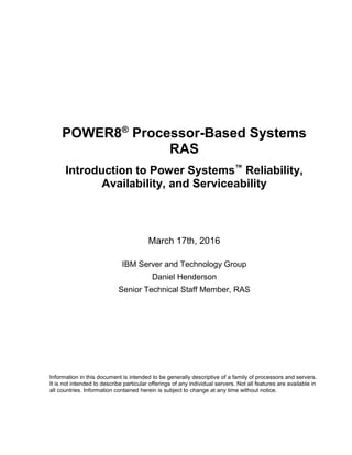
System Structure
Figure 8 below gives a reasonable representation of the components of a fully populated E850 server.
The figure illustrates the unique redundancy characteristics of the system. Power supplies are configured
with a N+1 redundant capability that maintains line-cord redundancy when power supplies are properly
connected to redundant power sources.
Fan rotors within the system also maintain at least an N+1 redundancy, meaning the failure of any one
fan rotor, absent any other fault, does not cause a problem with system overheating when operating
according to specification.
Fans used to cool the CEC planar and components associated with it are also concurrently maintanable.
There are additional fans in the lower portion of the system used to cool components associated with the
RAID controller/storage section. These fans can not be repaired concurrently. Therefore the system is
supplied with sufficient fan rotors to ensure N+1 redundancy, and in addition two additional fan rotors are
provided. The additional fan rotors are considered as integrated spares that do not require replacing.
This configuration allows the system to run with two of these fan rotors failed, without requiring a repair,
and the system still maintains n+1 fan rotor redundancy.
Given the amount of sparing built in, there is a very low expecation of needing to take a system down to
repair any of these fans. Should such a repair be necessary, however, the entire set of 8 fans would be
replaced in a single repair action.
As in other systems, the power supplies take AC power inputs and convert to a single 12 volt dc level.
Voltage regulator modules (or VRMs) are then used to convert to the various voltage levels that different
components need (1.2 volts, 3.3 volts. etc.)
As the general rule the design for such a VRM can be described as consisting of some common logic
plus one or more converters, channels, or phases. The IBM Power System E850 provides one more such
phase than is needed for any voltage output that is distributed to critical elements such as a processor or
memory DIMM.
The module(s) supplying the processor core and cache elements are replaceable separate from the CEC
planar. If one of the phases within the module fails, a call for repair will be made, allowing for redundancy
of these components. For other cases, such as the module cards supplying memory DIMMS, the extra
phase is used as an integrated spare. On the first phase failure in such a VRM, the system continues
operation without requiring a repair, thus avoiding outage time associated with the repair.
It should be noted that, when a component such as a processor module or a custom memory DIMM is
supplied voltage levels with redundant phases, redunancy typical ends at the processor or CDIMM. On
21. Page 23
POWER8 Processor Based Systems RAS, January 2016
some devices, such as for a memory DIMM the can be some sort of voltage converter to further divide a
voltage level for puposes such as providing a reference voltage or signal termination. Such on-component
voltage division/regulation is typically not as demanding an activitiy as previously discussed and is not
included in that discussion of voltage regulation.
Figure 8: A Schematic of a IBM Power System E850
Comparing the IBM Power System E850 to POWER7 based IBM Power System 750 and 760
Figure 6: Comparing Power System RAS Features, gives a quick reference comparing the main features
of various POWER7 and POWER8 processor based systems. The table illustrates significant areas
where the availability characteristics of the E860 have advanced over what POWER7 provided.
These include processor and memory enhancements such as the integration of the I/O hub controller into
the processor chip, the use of enterprise memory. The infrastructure was also improved in key areas
especially by providing redundancy and sparing for critical voltage converter phases. Other such
improvements included more redundancy in the op panel function, and the ability to dynamically replace
the battery used to back-up time of day information when the system is powered off.
Sockets/components plugged into a planar
Components that collectively
provide at least n+1 redundancy
and can be concurrently replaced
Single FRU with some Internal
Redundant/spare Components
Components within a FRU collective
providing at least N+1 redundancy
Pwr
Supply
CEC Planar
Fan
Fan
Fan
Fan
Pwr
Supply
Pwr
Supply
Pwr
Supply
Core
Cache
VRMs
Integrated Spare Component
Planar Board
Other Interface elements
Other
Volt.
Processor
DCM
Custom DIMMs
Processor
DCM
Processor
DCM
Processor
DCM
Various
Service
Functions
I/O Planar
Fan
PCIeGen3x16Slot
From DCM 2From DCM 0 From DCM 1
PCIe
Switch
Module
From DCM
USB3.0
RAID Planar
RAID Ctrl RAID Ctrl
DVD Op Panel
Thermal
Sensor
Thermal
Sensor
Thermal
Sensor
8 SFF
SSD
Storage
Global
Service
Processor
Card
Processor
Clock
VPD Card
Sys
VPD
Sys
VPD
Battery
Other
Voltge
May be configured for redundancy
Components integrated on a planar
Concurrently replaceable
Slot or bay supporting concurrent repair
Other ComponentsFan Fan Fan Fan Fan Fan Fan Fan
Components that collectively provide
at least n+1 redundancy
Note: Fan refers to a single rotor. Multiple fan rotors may
be packaged as single field replaceable unit(FRU)
PCIeGen3x16Slot
PCIeGen3x8Slot
PCIeGen3x16Slot
PCIeGen3x16Slot
PCIeGen3x16Slot
PCIeGen3x16Slot
PCIeGen3x8Slot
PCIeGen3x8Slot
Component within a FRU with n-mode
capability
22. Page 24
POWER8 Processor Based Systems RAS, January 2016
These systems are now enabled with options to use enterprise features of the PowerVM such as active
memory mirroring of the hypervisor and Capacity on Demand. These functions, described in detail later in
this document, also can enhance availability when compared to scale-out systems or the prior generation
IBM Power System 750/760.
Comparing the IBM Power System E850 to IBM Power System E870 and IBM Power System
E880
There are still some significant differences between the IBM Power System E850 and the E870/E880
Systems that can impact availability.
The latter systems have a redundant clock and service processor infrastructure which the E850 lacks.
As will be discussed in the next sub-section, the IBM Power E870 and E880 systems can expand beyond
4 sockets by adding additional 4 socket system node drawers. When one of these systems is configured
with more than one such drawer, there is the added RAS advantage that a system can IPL with one of the
drawers disabled, using resources of the remaining drawers in the system. This means that even if there
was a fault in one of the system node drawers so severe that it took the system down and none of the
resources in that drawer could subsequenlty be used, the other drawers in the system could still be
brought back up and put in to service.
This would not be true of an E850 system.
POWER8 processor-based IBM Power System E870 and IBM Power System E880
Introduction
On October 6th, 2014, IBM introduced two new enterprise-class Power Servers based on a single core
module (SCM) version of the POWER8 processor. The SCM, provides additional fabric busses to allow
processors to communicate with multiple 4-socket drawers allowing system scaling beyond 4 sockets
supported by the DCM module.
Figure 9: POWER8 SCM
Accordingly, the basic building-block of an IBM Power E870 or IBM Power E880 system is a 4 process-
socket system node drawer which fits into a 19” rack. Each node drawer also includes 32 DIMM sockets
and 8 PCIe I/O adapter slots. Announced systems support 1 or 2 such system nodes.
SCM Module
PCIe A0 Bus A1 Bus A2 Bus
Mem
Bus
Mem
Bus
Mem
Bus
Mem
Bus
Mem
Bus
Mem
Bus
Mem
Bus
Mem
Bus
Core Core
L2 L2 L2
L3
Mem
Ctrl
Interconnect
/ Pervasive
On Chip
Accelerators
Bus
Ctrl
Core Core Core
L2 L2 L2
L3
On Chip
Ctrl
PCIe
Ctrls
/Bridges
Bus
Ctrl
PCIe
Mem
Bus
Mem
Bus
Mem
Bus
Mem
Bus
Mem
Bus
Mem
Bus
Mem
Bus
Mem
Bus
CoreCoreCore
L2L2L2
L3
Mem
Ctrl
CoreCore
L2L2L2
L3
X0 Bus X1 Bus X2 Bus X3 Bus
Similar to Processor used in
1s and 2s Servers
Packaged in a larger Single Chip
Module as opposed to a Dual
Chip module
Supports Multiple nodes
(CEC drawers)
With more bandwidth compared
to POWER7/POWER7+
23. Page 25
POWER8 Processor Based Systems RAS, January 2016
In addition to the system nodes, each Power E870 or E880 system includes a separate system control
unit also installed into a 19” rack and connected by cables to each system node. The system control node
contains redundant global service processors, clock cards, system VPD and other such system-wide
resources.
Figure 10 gives a logical abstraction of such a system with an emphasis on illustrating the system control
structure and redundancy within the design.
Figure 10: Logical View of Power System E870/E80 System Structure
The figure illustrates a high level of redundancy of the system control structure (service processor,
clocking, and power control) as well as power and cooling.
Most redundant components reside on redundant cards or other field replaceable units that are powered
and addressed independently of their redundant pairs. This includes the redundant global and local
service processor functions and clocks, the power interface that provides power to from the system nodes
to the System control unit, as well as system fans.
There is only one system VPD card and one Op Panel, but the system VPD is stored redundantly on the
system VPD card, and there are three thermal sensors on the Op panel ensuring no loss of capability due
to the malfunction of any single sensor.
At the CEC-level there are voltage regulator modules (VRMs) packaged in Voltage Regulator Module
(VRM) cards that are individually pluggable. Each such VRM can be described as having some common
elements plus at least three components (known as converters, channels or phases) working in tandem.
Proper function can be maintained even if two of these phases fail, so by definition the design allows for
phase redundancy and in addition contains an additional spare phase. Using the spare phase prevents
the need to replace a VRM card due to a failure of a single phase.
System Control Unit Drawer
DVD
(optional)
Op Panel
Global
Service
Processor
Card
Global
Clock
Logic
Fan
VPD Card
Sys
VPD
Sys
VPD
Global
Service
Processor
Card
Global
Clock
Logic
Fan Fan Fan
Thermal
Sensor
Thermal
Sensor
Thermal
Sensor
RTC
Battery
RTC
Battery
Redundant Field Replaceable Unit (FRU)
FRU with some Internal Redundant/spare Components
Redundant Componentswithin a FRU
Other Components
System Node Drawer
Pwr
Supply
Fan
Fan
Fan
Fan
Pwr
Supply
Pwr
Supply
Pwr
Supply
Local
Service
Functions
Local
Service
Functions
Power
Interface
Power
Interface
Local Clock/
Ctrl
Local Clock/
Ctrl
VRM
VRM
VRM
VRM
…
Spare Component within a FRU
Cables connect FSP/Clock and Power
Between System Control Unit
And System Node Drawers
AC Input Source 1
AC Input Source 2
Main Planar Board
Other Interface Component
System Node Drawer
Pwr
Supply
Fan
Fan
Fan
Fan
Pwr
Supply
Pwr
Supply
Pwr
Supply
Local
Service
Functions
Local
Service
Functions
Power/
Interface
Power/
Interface
Local Clock/
Ctrl
Local Clock/
Ctrl
VRM
VRM
VRM
VRM
…
Pwr
In.
Pwr
In.
Pwr
In.
Pwr
In.
Fan
24. Page 26
POWER8 Processor Based Systems RAS, January 2016
New in POWER8, the battery used to maintain calendar time when a Flexible Service Processor (FSP)
has no power is now maintained on a separate component. This allows the battery to be replaced
concurrently separate from the service processor.
In the design, fans and power supplies are specified to operate in N+1 redundancy mode meaning that
the failure of a single power supply, or single fan by itself will not cause an outage. In practice, the actual
redundancy provided may be greater than what is specified. This may depend on the system and
configuration. For example, there may be circumstances where the system can run with only two of four
power supplies active, but depending on which power supplies are faulty, may not be able to survive the
loss of one AC input in a dual AC supply data-center configuration.
Compared to POWER7 based IBM Power System 795
Individuals familiar with the POWER7 based Power 795 system will find similarities in the IBM Power
E870/E880 design. Among the differences, however, is that the E870/E880 systems contain the global
control functions with a separate drawer using cables to connect to each system node drawer, rather than
making use of a large central backplane.
Also significantly, taking advantage of the integration of the PCIe controller into the processor, the E870
and E880 systems have 8 PCIe slots, each capable of supporting a PCIe adapter within the system node
drawer, or connection to an external I/O expansion drawer. In contrast the POWER7 processor based
795 systems only supported I/O expansion drawers.
Figure 11 illustrates similarities and differences as well as some of the significant improvements in the
system structure between the two systems.
Figure 11: Some Power System Featuresa E870/E880 Compared to 795
Area POWER7 795 System POWER8 4+ Socket Enterprise
Systems
System
Structure
Similarities
Global Service Processor/Clocks
distributed to all processor books so
that redundancy available in all
configurations.
N+1 Redundant power and cooling
Redundant External Thermal/Power
Monitoring Control Module
Global Service Processor/Clocks so that
redundancy available in all configurations
N+1 Redundant power and cooling
Thermal Power/Monitoring Control
integrated into each Processor Module
System
Structure
Differences
4 Socket Processor Books
24” Rack
Single Central Backplane
interconnected
I/O hub function external to processor
required for I/O
I/O drawers required for I/O
4 Socket System Node Drawers
19” Rack
Drawers Cable Interconnected with more
bandwidth capability using positive
latching connectors
I/O hub function integrated into processor
(no external I/O hub required)
Integrated I/O Slots available
Optional I/O drawers
Triple Redundant Ambient Temperature
Sensors
25. Page 27
POWER8 Processor Based Systems RAS, January 2016
Planned
Outage
Avoidance
Concurrent repair of fans/power
supplies, FSP
Concurrent repair of PCIe adapters,
DASD when configured for redundancy
CHARM for repair of systems with 2 or
more nodes required removing
resources from one node during node
repair
Concurrent repair of fans/power supplies,
clock batteries as component separate
from the FSP
Concurrent repair of PCIe adapters,
DASD when configured for redundancy
Emphasis on Live Partition Mobility to
ensure application availability during
planned outages regardless of the number
of nodes
Compared to POWER7 based IBM Power System 770/780
Readers familiar with the POWER7 processor-based 770 and 780 servers will also see some similarities
in the basic system structure, but will also see a significant number of differences and improvements.
These include that the global service processors and clocks are made redundant in the system design
even when a single system node drawer is used. That was not the case with the 770 or 780 single node
systems.
Figure 12: Power System E880 and E870 Compared to 770/780
Area POWER7+ 770/780 System POWER8 4+ Socket Enterprise Systems
System
Structure
Similarities
1-4 CEC drawers (Drawers, 4
sockets max each drawer)
19” Rack
Drawers Cable Interconnected
Integrated I/O and I/O Slots
N+1 Redundant power and cooling
Optional I/O drawers
1-4 CEC Drawers (Drawers, 4 sockets max
each drawer)
19” Rack
Drawers Cable Interconnected
Integrated I/O Slots
N+1 Redundant power and cooling
Optional I/O drawers
System
Structure
Differences
Redundant FSP/Clocks only
available in systems with 2 or more
CEC drawers
Some critical voltage regulators
integrated on planars
Single ambient temperature sensor
Single power/thermal control module
I/O hub controllers external to
processor for integrated and
attached I/O required
Separate I/O planar required for
integrated I/O
Integrated DASD Options
Global FSP/Clock in separate drawer
provides redundancy for 1 drawer (4 socket)
systems
Extensive improvements in power/cooling
design/reliability including:
Critical CEC-level Voltage
Regulation on pluggable modules
with N+1 phase design with
integrated spare phase
Triple redundant ambient
temperature sensors
Power/Thermal management
integrated into each processor
No external I/O hub required
No separate I/O planar for integrated I/O
needed
No integrated DASD options
26. Page 28
POWER8 Processor Based Systems RAS, January 2016
Planned
Outage
Avoidance
Concurrent repair of fans/power
supplies
Concurrent repair of PCIe adapters,
DASD when configured for
redundancy
Clock Batteries integrated into FSP
function (not individually concurrently
maintainable)
CHARM for repair of systems with 2
or mode nodes required removing
resources of one node during node
repairs
Concurrent repair of fans/power supplies
Concurrent repair of PCIe adapters, DASD
when configured for redundancy
Separately concurrently clock batteries
Emphasis on Live Partition Mobility to
ensure application availability during
planned outages
And again, integration of the PCIe controller into the processor allows the E870/E880 systems to support
integrated I/O slots without the need for a separate I/O planar.
CEC Hot Add Repair Maintenance (CHARM)
The bulk of all hardware replacements in an E870/E880 system are expected to be of components for
which individual concurrent maintenance can be performed: power supplies, fans, I/O adapters and
devices, clock batteries, and so forth.
However, some repairs cannot be made concurrently with system operation.
In POWER7, PowerVM Enterprise Edition supported the concept of Live Partition Mobility (LPM). LPM,
which is discussed in detail elsewhere in this whitepaper, allows a properly configured partition virtualized
under PowerVM to be migrated from one system to another without partition termination.
Migrating partition from one system to another allows for application continuity in the event a system
requires an outage for repair.
In addition, Power Systems 795, 770 and 780 also support the concept of allowing one node (processor
book or CEC drawer) to be removed from a running system configuration for repair while the other
processor/books or drawers would continue to be powered on and run work-load.
This feature requires that all of the workload running in the load would have to be “evacuated” from the
node before such a repair could be made. Processor and memory in Power Systems using PowerVM are
virtualized. Therefore if sufficient resources could be found within other nodes in the system to take up
the workload to be evacuated, and I/O was redundant and properly virtualized, it would be possible to
evacuate a node and perform this repair without application outage.
LPM (important for not only service, but overall workload management) continues to be enhanced for
Power Systems, including advancements in terms of performance and ease of use.
Anticipating the use of the more flexible LPM, CHARM is not a feature provided in IBM Power E870/E880
systems.
There are a number of reasons for this:
Dynamic node repair could not be supported on systems with single nodes. In practice systems
with just two nodes may also find it difficult to find enough resources for a successful node
evacuation.
CHARM only handles failures within a node and with some limitations. Repair of some global
resources, even with CHARM still require a planned system-wide outage.
Use of CHARM for planned outage avoidance is limited to hardware failures. It doesn’t assist in
keeping applications running during an upgrade of firmware to one level to another, during load
re-balancing across systems or other software related reasons for partition planned outages.
27. Page 29
POWER8 Processor Based Systems RAS, January 2016
CHARM does not mitigate the impact of unplanned partition reboots. Minimizing the impact of
unplanned partition outages is often achieved through system clustering (PowerHA System-Mirror
for example). In such clustered environments planned outages will often be minimized by LPM or
other application failover regardless of CHARM capabilities.
PCIe Gen 3 I/O Expansion Drawer
PCIe Gen3 I/O Expansion Drawers can be used in systems to increase I/O capacity.
Figure 13: PCIe Gen3 I/O Drawer RAS Features
These I/O drawers are attached using a connecting card called a PCIe3 cable adapter that plugs in to a
PCIe slot of the main server.
Each I/O drawer contains up to two I/O drawer modules. An I/O module uses 16 PCIe lanes controlled
from a processor in a system. Currently supported is an I/O module that uses a PCIe switch to supply six
PCIe slots.
Two different active optical cable are used to connect a PCIe3 cable adapter to the equivalent card in the
I/O drawer module. While these cables are not redundant, as of FW830 firmware or later; the loss of one
cable will simply reduce the I/O bandwidth (number of available lanes available to the I/O module) by
50%.
Infrastructure RAS features for the I/O drawer include redundant power supplies, fans, and DC outputs of
voltage regulators (phases).
The impact of the failure of an I/O drawer component can be summarized for most cases by the table
below.
Gen3 I/O Drawer
x8 x8
I/O Module
Optics Interface
I/OSlot
I/OSlot
I/OSlot
I/OSlot
I/OSlot
I/OSlot
PCIe Switch
x8 x8
I/O Module
Optics Interface
I/OSlot
I/OSlot
I/OSlot
I/OSlot
I/OSlot
I/OSlot
PCIe Switch
Mid-plane
Chassis
Management
Card
Fan
Fans
Pwr
Pwr
Optical Connections to CEC DrawerPCIe Gen 3 I/O Expansion
Drawer RAS Design Features
• Fan Out I/O modules run independently
• Single Chassis Management Card for
pwr/temp monitoring and control
• Is not a run-time single point of
failure
• Fans and power will run in a
safe mode if needed
• Rare faults such as on mid-plane
could still cause drawer outage
• Redundancy in
• Fans/Power Supplies
• Key voltage regulator phases
28. Page 30
POWER8 Processor Based Systems RAS, January 2016
Figure 14: PCIe Gen3 I/O Expansion Drawer RAS Feature Matrix
Faulty Component Impact of Failure Impact of Repair Prerequisites
I/O adapter in an I/O
slot
Loss of function of the
I/O adapter
I/O adapter can be
repaired while rest of the
system continues to
operate.
Multipathing/ I/O adapter
redundancy, where
implemented, can be
used to prevent
application outages
First Fault on a Data
lane (in the optics
between the PCIe3
cable adapter card
in the system and
the I/O module)
None: Spare Used No Repair Needed:
Integrated Sparing
Feature
Full functionality
implemented in FW830
A Second Data Lane
fault or other failure
of one active optics
cable
System continues to
run but numer of
active lanes available
to I/O module will be
reduced
Associated I/O module
must be taken down for
repair; rest of the system
can remain active.
Described functionality
implemented in FW840
firmware*. Earlier FW
levels may lose all of the
I/O in the associated I/O
module
Other Failure of
PCIe3 cable adapter
card In System or
I/O module
Loss of access to all
the I/O of the
connected I/O Module
Associated I/O module
must be taken down for
repair; rest of the system
can remain active.
Described functionality
implemented in FW840*
on systems with an HMC
One Fan System continues to
run with remaining fan
Concurrently repairable
One Power supply System continues to
run with remaining fan
Concurrently repairable
Voltage Regulator
Module associated
with an I/O module
System continue to
run for a phase failure
transition to n mode.
Other faults will impact
all the I/O in the
Module
Associated I/O module
can not be active during
repair; rest of the system
can remain active.
Described functionality
implemented in FW840*
on systems with an HMC
Chassis
Management Card
(CMC)
No Impact to running
system, but once
powered off, the I/O
drawer can not be re-
integrated until CMC is
repair
I/O drawer must be
powered off to repair (loss
of use of all I/O in the
drawer)
Described functionality
for systems with an HMC
Midplane Depends on source of
failure, may take down
entire I/O drawer
I/O drawer must be
powered off to repair (loss
of use of all I/O in the
drawer)
Described functionality
for systems with an HMC
*FW840 is not currently available for IBM Power System E850. Systems running FW levels prior
to FW840 must have the entire I/O drawer powered off for repair of these components.
It should be noted that in addition to the above, the E880/E870 Power Systems do support the concurrent
add of a cable card in support of adding an I/O drawer to a system starting with FW840 firmware. They
also support adding an I/O drawer to the system. Adding an I/O module to an existing I/O drawer
concurrently is not supported.
29. Page 31
POWER8 Processor Based Systems RAS, January 2016
Section 2: Hallmarks of Power Systems RAS
This section will give a detailed discussion of the common RAS features of Power Systems based on the
POWER8 processor.
Before discussing the details of the design, however, this subsection will summarize some of the key
characteristics that tend to distinguish Power Systems compared to other possible system designs.
Integrated System Design
IBM Power Systems all use a processor architected, designed and manufactured by IBM. IBM systems
contain other hardware content also designed and manufactured by IBM including memory buffer
components on DIMMs, service processors and so forth.
Additional components not designed or manufactured by IBM, are chosen and specified by IBM to meet
system requirements, and procured for use by IBM using a rigorous procurement process that delivers
reliability and design quality expectations.
The systems that IBM design are manufactured by IBM to IBM’s quality standards.
The systems incorporate software layers (firmware) for error detection/fault isolation and support as well
as virtualization in a multi-partitioned environment.
These include IBM designed and developed service firmware for the service processor. IBM’s PowerVM
hypervisor is also IBM designed and supported.
In addition, IBM offers two operating systems developed by IBM: AIX and IBM i. Both operating systems
come from a code base with a rich history of design for reliable operation.
IBM also provides middle-ware and application software that are widely used such as IBM WebSphere®
and DB2® pureScale™ as well as software used for multi-system clustering, such as various IBM
PowerHA™ SystemMirror™ offerings.
All of these components are designed with application availability in mind, including the software layers,
which are also capable of taking advantage of hardware features such as storage keys that enhance
software reliability.
30. Page 32
POWER8 Processor Based Systems RAS, January 2016
Figure 15: IBM Enterprise System Stacks
Where IBM provides the primary design, manufacture and support for these elements, IBM as a single
company can be responsible for integrating all of the components into a coherently performing system,
and verifying the stack during design verification testing.
In the end-user environment, IBM likewise becomes responsible for resolving problems that may occur
relative to design, performance, failing components and so forth, regardless of which elements are
involved.
Being responsible for much of the system, IBM puts in place a rigorous structure to identify issues that
may occur in deployed systems, and identify solutions for any pervasive issue. Having support for the
design and manufacture of many of these components, IBM is best positioned to fix the root cause of
problems, whether changes in design, manufacturing, service strategy, firmware or other code is needed.
Alternate System Approach
In contrast, other systems may be designed in a less integrated fashion. The company integrating the
system hardware may not have designed the processor or any of the other components integrated into
the system besides the system boards and mechanical hardware.
That vendor may be responsible for the system manufacture and test, but may have to do so without the
benefit of the detailed knowledge of the internal design of the components being integrated.
The systems sold by the vendor may run using other vendor’s designs for the firmware layers such as the
hypervisor, as well as the operating system, other virtualization software, and typically also middle-ware
and applications.
When it comes to resolving issues in deployed systems, the system vendor may be responsible for
replacing failed hardware, but be unable to effectively resolve issues in components the vendor does not
design.
When pervasive issues are discovered in components not manufactured or developed by the vendor, the
ability to address the issue may be severely restricted.
Computational Layer
Hypervisor/Virtualization
I/O Layer
Proc/Mem
DIMMs
I/O Adapters +
DevicesCache Coherent
Accelerators
I/O Bridges
Infrastructure
Service Procs Clocks Pwr Supplies Fans
I/O
Partitioning Live Partition
Migration
Partition Layer
Operating System
Middle-ware
Database
Other Apps
Processors
IBM Architecture/Design/
Mfg/Test
IBM Architecture
And System Integration
Verification/Test
Misc Vendor
Architecture/
Design
IBM Test
Computational Layer
Hypervisor/Virtualization
I/O Layer
Proc/Mem
DIMMs
I/O Adapters +
DevicesI/O Bridges
Infrastructure
Service Procs Clocks Pwr Supplies Fans
I/O
Partitioning
Partition Layer
Operating System
Middle-ware
Database
Other Apps
Processors
System Vendor
Architecture/Design/
Mfg/Test
System Vendor Architecture
And System Integration
Verification/Test
All Other colors
Represent Other
Vendors
IBM Power System with PowerVM®, AIX® and DB2®
Alternate Hardware and Software Stack
System Firmware
System Firmware
31. Page 33
POWER8 Processor Based Systems RAS, January 2016
Hardware That Takes Care of the Hardware
The need for hardware to largely handle hardware faults is fundamental to the Power System design.
This means that the error detection, fault isolation and fault avoidance (through recovery techniques, self-
healing and etc.) of processors, memory, and hardware infrastructure, are primarily the responsibility of
the hardware. A dedicated service processor or specific host code may be used as part of the error
reporting or handling process, but these firmware layers, as supplied by IBM, are considered part of the
hardware as they are designed, tested and supported along with the underlying hardware system.
Figure 16 below indicates the way in which this handling can be contrasted to an alternative design
approach. In the alternative approach, the hardware is considered “good enough” if it is able to transmit
error information to software layers above it. The software layers may be capable of mitigating the impact
of the faults presented, but without being able to address or repair the underlying hardware issue.
Figure 16: Two Concepts of Server RAS
32. Page 34
POWER8 Processor Based Systems RAS, January 2016
Figure 17: Two Approaches to Handling an Uncorrectable Cache Fault (Unmodified Data)
Figure 17 gives an example how even on a software stack not supplied by IBM, an uncorrectable fault in
unmodified data in a cache can be detected, isolated, and permanently addressed entirely within the
context of IBM supplied hardware and firmware.
This is contrasted with a potential alternate design in which the fault condition is reported to software
layers. Co-operation of a hypervisor, operating system, and possibly even a specific application may be
necessary to immediately avoid a crash and survive the initial problem.
However, in such environments the software layers do not have access to any self-healing features within
the hardware. They can attempt to stop using a processor core associated with a cache, but if a cache
line were beginning to experience a permanent error during access, the sheer number of errors handled
would likely soon overwhelm any ability in the software layers to handle them. An outage would likely
result before any processor migration would be possible.
Simply removing the faulty cache line from use after the initial detected incident would be sufficient to
avoid that scenario. But hardware that relies on software for error handling and recovery would not have
such “self-healing” capabilities.
Detailed Level 3 cache error handling will be discussed later.
The key here is to understand that the Power Systems approach is in stark contrast to a software based
RAS environment where the hardware does little more than report errors to software layers and where a
hypervisor, OS or even applications must be primarily responsible for handling faults and recovery.
Based on what was possible in early generations of POWER, Power Systems do also allow for some of
the same kinds of software behaviors found in the alternate approach. But, because of the hardware retry
and repair capabilities in current POWER processor-based systems, these can be relegated to a second
or third line of defense.
As a result, the hardware availability is less impacted by the choice of operating systems or applications
in Power Systems.
1. Hardware under service processor or system firmware purges the cache-line
and deletes it, preventing the fault from re-occurring in that cache line
2. Data is re-loaded from DIMMs as normal HW caching process on cache
miss
3. Service Processor handles recording fault and any subsequent Service
actions
If the fault is solid but limited to single cache line, there will be no subsequent errors
If fault is multi-bit solid, service processor may recognize a pattern of events and
implement a self-healing feature depending on the cache capabilities
1. Hardware detects the error
2. * If supported, the Hypervisor takes notice of the error and handle
recording/reporting fault, otherwise an outage
3. * If supported OS is told which application is using the data, if data
can be paged in from memory, OS will do so, outage if not
supported
4. * If not in a paged area of OS, OS if supported may notify
application, otherwise an outage
5. * Application, if it supported, can attempt to recover the data from
memory, etc., otherwise an outage
But all of this does nothing to the hardware to prevent the next error
If fault is solid, expect an eventual unplanned outage
IBM Power System with Non-IBM OS, Hypervisor and Software Alternate Approach
Computational Layer I/O Layer
DIMMs
I/O Adapters +
DevicesCache Coherent
Accelerators
I/O Bridges
Infrastructure
Service Procs Clocks Pwr Supplies Fans
Processors
Computational Layer
Hypervisor/Virtualization
I/O Layer
Proc/Mem
DIMMs
I/O Adapters +
DevicesI/O Bridges
Infrastructure
Service Procs Clocks Pwr Supplies Fans
I/O
Partitioning
Partition Layer
Operating System
Middle-ware
Database
Other Apps
Processors
2*
4*
3*
1,2
3
1
5*
Partition Layer
Operating System
Middle-ware
Database
Other Apps
Hypervisor/Virtualization
Proc/Mem I/O
Partitioning
System Firmware
1
33. Page 35
POWER8 Processor Based Systems RAS, January 2016
Leveraging Technology and Design for Soft Error Management
Soft errors are faults that occur in a system and are either occasional events inherent in the design or
temporary faults that are due to an external cause.
For data cells in caches and memory and the like, an external event such as caused by a cosmic ray
generated particle may temporarily upset the data in memory. Such external origins of soft errors are
discussed in detail in Section Six.
Busses transmitting data may experience soft errors due to a clock drift or electronic noise.
Logic in processors cores can also be subject to soft errors where a latch may also flip due to a particle
strike or like event.
Since these faults occur randomly and replacing a part with another doesn’t make the system any more
or less susceptible to them, it makes sense to design the system to correct such faults without interrupting
applications, and to understand the cause of such temporary events so that parts are never replaced due
to them.
Protecting caches and memory against such faults primarily involve using technology that is reasonably
resistant to upsets and also by implementing an error correction code that corrects such errors.
Protecting data busses typically involves a design that detects such faults, allowing for retrying of the
operation and, when necessary, resetting the operating parameters on the bus (retraining) all without
causing any applications to fail.
Handling faults in logic is more difficult to accomplish, but POWER processors since POWER6® have
been designed with sufficient error detection to not only notice key typical software upsets impacting
logic, but to notice quickly enough to allow processor operations to be retried. Where retry is successful,
as would be expected for temporary events, system operation continues without application outages.
Alternate System Designs
It can be difficult to discover the degree to which an alternate system design protects against these soft
error events.
Certain arrays such as caches may be protected with an error correction code capable of fixing a single
bit upset by an external source, but not able to handle the occasional double-bit upset which might occur
when a cosmic ray particle releases more energy than can be confined to a single bit.
Processors, memory buffers and other logic structures may not be particularly protected and vendors not
advertising advanced features such as processor instruction retry, memory buffer replay, and so forth
may simply take the approach that detection, but not recovery, is sufficient soft error protection.
In environments without good fault isolation, it may not even be possible to distinguish between a
randomly occurring crash due to a hardware soft error event, and a random code bug causing an outage.
Strategic Spare Capacity Leveraged to Self-Heal Hardware
POWER processors and memory used in systems have built in spare capacity to allow for something that
fails to be substituted during run-time with a spare in order to avoid any outage due to the fault or for a
repair.
Examples include a spare data lane on a bus, a spare bit-line in a cache, or a spare DRAM module on a
DIMM.
34. Page 36
POWER8 Processor Based Systems RAS, January 2016
Figure 18: Approaches to Handling Solid Hardware Fault
For certain more severe events solid events, such as when a processor core fails in such a way that it
cannot even complete the instruction that it is working on, Alternate Processor Recovery allows another
processor to pick up the workload on the instruction where the previous one left off.
Alternate Processor Recovery does depend on the hypervisor cooperating in the substitution. Advanced
hypervisors such as found in PowerVM are able to virtualize processor cores so long as there is any
spare capacity anywhere in the system, no application or operating system awareness is required.
At a system design level, various infrastructure components, power supplies, fans, and so forth may use
redundancy to avoid outages when the components fail, and concurrent repair is then used to avoid
outages when the hardware is replaced.
System Level RAS Rather Than Just Processor and Memory RAS
IBM builds Power systems with the understanding that every item that can fail in a system is a potential
source of outage.
While building a strong base of availability for the computational elements such as the processors and
memory is important, it is hardly sufficient to ensure application availability.
The failure of a fan, a power supply, a voltage regulator or a clock oscillator or I/O adapter may actually
be more likely than the failure of a processor module designed and manufactured for reliability.
IBM designs systems from the start with the expectation that the system must be generally shielded from
the failure of these other components where feasible and likewise that the components themselves are
highly reliable and meant to last. Moreover when running without redundancy the expectation is that
under normal operation the non-redundant component is capable of carrying the workload indefinitely
without significantly decreasing the expected reliability of the component.
Greater than four socket Enterprise Power systems extend redundancy to include clock oscillators,
service processors, and even the CEC-level voltage regulator phases within a drawer.
35. Page 37
POWER8 Processor Based Systems RAS, January 2016
Section 3: POWER8 Common RAS Design Details
POWER8 Common: Introduction
The previous section notes that system RAS involves more than just processor and memory RAS, and
more than just hardware RAS.
Power Systems all do share a POWER based processor in common, however, and the RAS features
associated with the processor and by extension the memory and I/O paths are keys elements common to
application availability in any Power System design.
These design elements, referred to more generally as the computational elements can generally be
discussed independent of the design attributes of any particular Power System.
POWER8 Common: Architecture and Technology
Error Reporting and Handling
First Failure Data Capture Architecture
POWER processor-based systems are designed to handle multiple software environments including a
variety of operating systems. This motivates a design where the reliability and response to faults RAS in
the computational elements is largely independent of the software layers. Power Systems that include the
dedicated service processor primarily use code running on the service processor for detecting, managing
and resolving such faults, and ensuring that system operations continue or are recovered afterwards.
This approach is beneficial to systems as they are deployed by end-users, but also has benefits in the
design, simulation and manufacturing test of systems as well.
Putting this level of RAS into the hardware cannot be an after-thought. It must be integral to the design
from the beginning, as part of an overall system architecture for managing errors. Therefore, during the
architecture and design of a processor, IBM places a considerable emphasis on developing structures
within it specifically for error detection and fault isolation.
Each subsystem in the processor hardware has registers devoted to collecting and reporting fault
information as they occur. The design for error checking is rigorous and detailed. The value of data is
checked generally wherever it is stored. This is true, of course for data used in computations, but also
nearly any other data structure, including arrays used only to store performance and debug data.
Error checkers are derived for logic structures using various different techniques such as checking the
validity of state-machine transitions, defining and checking protocols for generated commands, doing
residue checking for certain computational instructions and by other means in an effort to detect faults
before the resulting impact propagates beyond the detecting sub-system.
The exact number of checkers and type of mechanisms isn’t as important as is the point that the
processor is designed for very detailed error checking; much more than is required simply to report during
run-time that a fault has occurred.
All of these errors feed a data reporting structure within the processor. There are registers that collect the
error information. When an error occurs, that event typically results in the generation of an interrupt which
is handled by the system’s dedicated service processor where available – an IBM designed processor
independent of the system processors.
Code within a hypervisor does have control over certain system virtualized functions, particularly as it
relates to I/O including the PCIe controller and certain shared processor accelerators. Generally areas in
these areas are signaled to the hypervisor.
In addition, there is still a reporting mechanism for what amounts to the more traditional machine-check or
checkstop handling.
36. Page 38
POWER8 Processor Based Systems RAS, January 2016
First Failure Data Capture Advantages
This detailed error detection and isolation capability has a number of key advantages over alternate
designs.
Being able to detect faults at the source enables superior fault isolation which translates to fewer parts
called out for replacement compared to alternative designs. IBM’s history indicates a real advantage in
calling out fewer parts on average for faults compared to other systems without these capabilities.
The POWER design also plays a key role in allowing hardware to handle faults more independently from
the software stacks as compared to alternatives.
Other advantages in fault handling, design verification and manufacturing test are discussed in greater
detail below.
Dedicated Service Processor Recoverable and Unrecoverable Error Handling
As mentioned, Power Systems provide a dedicated, IBM designed, service processor meant to access
the fault information of IBM designed modules such as the POWER8 processor.
Ideally the dedicated service processor primarily handles recoverable errors including orchestrating the
implementation of certain “self-healing” features such as use of spare DRAM modules in memory, purge
and delete of cache lines, using spare processor fabric bus lanes, and so forth.
However, the service processor, when handling an error, has access not only to the basic error
information stating what kind of fault occurred, but also access to considerable information about the state
of the system hardware – the arrays and data structures that represent the state of each processing unit
in the system, and also additional debug and trace arrays that are built into the hardware for performance
and error analysis purposes.
In the rare event that a system outage should result from a problem, the service processor has access to
this information as well as to the fault isolation registers normally deployed to manage error detection and
fault isolation.
Even if a severe fault causes system termination, this access can allow the service processor to
determine root cause of a problem, deallocate the failed components when so isolated, and allow the
system to restart with confidence that the problem has been resolved.
Should a failure point to a code design issue or other such problem, information collected by the service
processor, in conjunction with a hypervisor for code related problems should often be sufficient to identify
root cause of the problem, without the need for any sort of recreation. This expectation is based on
experience with several generations of POWER processor-based systems with similar capabilities.
Alternate Design
A processor could be designed with less error detection/fault isolation and recovery capabilities. Such an
alternate design might focus on sufficient error detection capabilities to note that a failure has occurred
and pass fault information to software layers to handle.
For errors that are “correctable” in the hardware – persistent single bit errors, for example, in a cache
corrected with an ECC algorithm, software layers can be responsible for predictively migrating off the
failing hardware (typically at the granularity of deallocating an entire processor core.)
For faults that are not correctable in hardware – such as double bit errors in a cache corrected with a
typical ECC algorithm, software layers are also responsible for “recovery.”
Recovery could mean “re-fetching” data from another place that it might be stored (DASD or memory) if it
was discovered badly in a cache or main memory. “Recovery” could mean asking a database to rebuild
itself when bad data stored in memory is found; or “recovery” could simply mean terminating an
application, partition or hypervisor in use at the time of the fault.