SlideShare a Scribd company logo
1 of 8
Download to read offline
Outer layer having
the largest diameter
with 25% of the
conventional mass
The second threshold
having 25% of the
conventional mass
distributed on 70% of
the diameter
The core-2 threshold
having 40% of the
conventional mass on
35% of the diameter
The core threshold
having 70% of the
mass on 25% of the
conventional
diameter
AEROCARD – CARD RE-ENGINEERING – AERODYNAMIC EQUILIBRIUM OF THE CARDING
CURVATURE
Presenting and communicating author: Debashish Banerjee- CEO- Blackstone Synergy
Consulting Group Limited, Nairobi-00604, Kenya (P.O. Box – 23365)
db@blackstonesynergy.com
The analysis of the core component shall reveal the following features:
1. Circular cross-section implies a uniform distribution of the discrete particles that
constitute the mass distribution map.
2. The packing of 70% of the original conventional mass in just 25% of the diameter
brings in greater compactness with so much so additional discrete particles crowding
either side of the central axis that makes the cylinder of the core concentric under stress
with higher rotational torque
3. The centrifugal force originating from the core shall be determined by the linear
velocity; approximately a multiple of 13.46 on the conventional cylinder. The kinetic
energy transmitted along the radial direction outwards shall be phenomenal (1200 % +);
an intense energy at that.
4. The function y describing energy transmitted outwards shall be denoted by y=f(x1)
where x1 is determined by the following variables:
a) Volume of displaced particles as defined by the torque summation on either side of
the axis,
b) The entropy in the system as defined by the density of the discrete particles in the
mass and
CORE-1 STRUCTURAL FUNDAMENTALS
THE TORQUE CONFIGURATION
AS DEFINED BY THE HIGH
PACKING DENSITY AND SMALLER
SURFACES
PARTITION CHANGES CAUSED WITHIN
THE STRUCTURE BY COLLISION PROFILE
CONFIGURATIONS A DIFFERENT
THRESHOLDS
c) The entropy gradient across cut-off lines -1, 2 and 3 in terms of torque stability as
determined by the material stability to temperature, collisions energy (high impact-low
frequency as well as low impact-high frequency) and specific material strength across
the cross-sectional masses.
5. The constant C1 in the equation is defined by the domain strength in terms of spatial
configuration of the energy distribution at the interface with the next boundary of the
composite.
The interface between the core-1 and the core-2 is vital in interpreting the trajectory of
the energy line as it permeates through the structure with varying particle density and
torque values.
There shall be an inherent displacement with an angle  determined by the relative
ratio of C1 and C2; both constants being determined by the same conditions as
explained above in the respective medium.
This deflection in term defines the volume of air displaced and the sharpness of the
curvature profile at the edges that change the vector of displacement of energy normal
to the impact.
ENERGY TRAJECTORY CHANGE CAUSED
BY SHIFTING PACKING DENSITIES
ANGULAR DEFLECTION
1 AT SHELL-1 & 2
BOUNDARY
CORE-1
SHELL
CORE-2
SHELL
FUNDAMENTAL CHANGES IN
STRUCTURAL TORQUE DYNAMICS
CAUSE THE ENERGY DEFLECTION IN
SPITE OF BASIC CONCAVITY OF THE
TWO SURFACES
In short, this singular important ratio defines the configuration of the rate of change of
the normal since the energy profile is spread over a greater curvature thereby reducing
the specific energy at the boundary and aggregating to a slower rate of change of the
normalization. This, in turn, spreads the distribution of the drawing vector on the fiber
mass at the eventual periphery on a larger cross-section thereby ensuring a gradual
separation leading to individualization and higher fiber freedom.
Energy deflection at the boundary is the first important derivative of the design proposal.
The structural analysis of the core-2 body has the following derivations:
1. The body is concentric with a balanced torque distribution within the coordinates.
2. However, the mass density is lower than in core-1 and consequently, the entropy in
the system is higher.
3. The C2 constant is lower in magnitude owing to higher spatial distribution of the
energy that is essentially lower in value as well when compared with the core-1
fundamentals.
4. The specific energy at the impacting points along the curvature at the boundary is
lower than in core-1 and hence the deflecting angle q2 for the energy shall also be
narrower and resulting in an acute angle as compared to q1.
5. Volume of air displaced is a function described in the equation :
Equation-2: y2 = f(x2) +C2 where x2 compares with x1 in the following manner:
2
Axes partitioning
the torque
configuration
within the
structure
TORQUE FUNDAMENTALS ARE
SPREAD OVER LOWER PACKING
DENSITIES AND ON LARGER
SURFACES AS COMPARED TO
SHELL OF CORE-1
CORE-2 STRUCTURAL DYNAMICS
a) Entropy is higher on account of lower packing density of the material defined by 35%
diameter and 40% mass; hence the spatial distribution of discrete particles representing
summation of mass is lower (assuming identical metallurgy and cross-sectional particle
diameter).
b) The entropy of the particles within the colliding medium in a dynamic motion shall be
higher causing a larger domain size for the coordinates described by an individual
particle – an important derivative in defining the consistency of air volume displaced and
the energy transmitted in the radial outwards direction from the composite nucleus.
c) Wider domain bounds of the particle coordinates also imply a higher linear curvature
of the impact.
The third layer of the composite cylinder is fundamentally oval in shape with 80% of the
conventional mass distributed in 70% of the diameter.
The center of gravity as defined by the coordinates of the composite nucleus is at 33%
level of the diameter of the oval structure implying that the structure balance is
achieving equilibrium at a lower position thereby lending stability.
The equation shall be y3 = f(x3) + C3
The constant C3 shall be different from the preceding ones described by C1 and C2in
the following aspects:
a) The energy curve shall be periodic in nature and not typically sinusoidal but shall
approximate an alternating parabola and an hyperbola with distinctly different
SHELL-3: STRUCTURAL ANALYSIS
3 – ACUTE ANGLE
ON THE ENERGY
PATH DEFLECTION AT
THE BOUND
amplitudes as determined by the coordinates of the center of gravity and measure of
eccentricity angle a as in the illustration.
b) The packing density defined by 80% on a spatial distribution of 70% diameter shall
reduce entropy significantly and constrain the bounds of x3 thereby ensuring a well
defined parabola and an equally sharp outline for the hyperbola; so very vital to ensure
a controlled pattern in the air density of the displaced volume and also in the transmitted
energy patterns within each revolution of the eccentric bounds.
The final phase of the composite has 100% of the mass packed in 100% of the outer
diameter of the oval shell; thereby increasing the packing density to minimize particle
entropy and controlling the domain bounds as described by the equation:
Equation for the outer shell: y4 = f(x4) + C4
The conditions as explained in the equation are:
CORE-4: OUTER SHELL STRUCTURE
ANGLE OF
DEFLECTION FOR THE
PARTICLES
ANGLE OF ECCENTRICITY
a) The CG of the composite nucleus is at 25% of the structural diameter (oval diameter
of the outer shell) implying a stabilizing point at a low equilibrium coordinates; in itself a
highly stable physical system is assured on a design perspective.
b) The bounds are well defined for x4 implying that the parabolic and hyperbolic curves
have sharp profiles and that the alternating high air volume is followed by a low
displaced volume thereby creating an air draft in the fiber field.
c) The measure of eccentricity as described by the angle a2 defines the amplitude of
the energy curve moving on an outward radial plane; hence in turn determining the
velocities of the displaced air volumes.
The above is an illustration that describes the operating layer of the carding zone and
the forces constituting the fiber field and has the following features as derivatives:
a) The operating layer in the conventional card is thicker and relatively uniform with the
normal changes over sharp curve domains.
In the design, the operating layer is reduced in thickness by the air draft caused by the
alternating parabola and hyperbola of the displacement trajectory of the air particles; a
derivative of the oval shape of the shell-3 and 4 of the cylinder composite.
b) The shear line is typically shoved up in the reference frame of the operating layer as
the wire sharpness depreciates on account of thrust load caused by the build-up of
fibers.
CONVENTIONAL
CARDING CURVATURE
Line of shear in the
latest models
Axis depicting the changes in
torque direction for the latest
models
FIG.1
FIG.2
Line of shear in the
proposed design
Axis depicting the larger change dynamics for
the torque vector direction owing to the
impact of specific mass distribution in the
staggered cylinder design
AERODYNAMIC DESIGN WITH STAGGERED
CYKINDER FOR VARYING SPECIFIC MASS
DISTRIBUTION
In the design, the energy density and the domain bounds as described by x3 and x4
progressively increase the curvature over which the normal changes; in effect the rate
of change of the normal is delayed causing the fibers to be gripped strongly on a wider
cluster length hereby effectively bringing down the coordinates of the line of shear; the
most important derivative of the design.
c) The conventional carding zone has the design issue of limited containment of the
fiber build-up in the operational layer owing to the transfer dynamics of the fibers to the
doffer zones. These are traditionally a function of the relative gap between the cylinder
and the doffer, the mutual concentricity of the two rotating elements. The geometric
positioning with respect to each other and the wire density of the cylinder with respect to
the doffer besides the profile and the tip hardening of the wires.
In the design, the oval structure of the shells in the composite and the varying intensities
that deflect the energy angles substantially from the original trajectory originating from
the nucleus and the significantly decreased rate of change of the normal of the radial
outwards energy impact contribute to waves of parabolic and hyperbolic profiles of the
displaced air. All of these contribute to a steady draft that contribute to a reduced
operational layer thickness, a distinctly lower coordinates for the line of shear and finally
the consistent heavy transfer of fibers onto the doffer.
The carding intensity of the design is significantly improves; in effect the dynamics of
yarn manufacturing is changed for good in a revolutionary manner.
The detailed mathematics at the curvature points for describing the surface
characteristics of the interfacing points between the shells progressively have been
avoided in this paper. That should come up for an expounding while collaborating with
the carding OEM.
This design is intended to change the dynamics of the yarn engineering process and
shall be the singularly most important factor in bringing in value in the textile chain in
terms of quality and product economy.
Finally, at the concluding stage, Blackstone Synergy intends to reach out to the
humanity through these innovations and try and make a difference in the lives of
humans affected by the economic crisis.

More Related Content

What's hot

Shear strength of rc deep beam panels – a review
Shear strength of rc deep beam panels – a reviewShear strength of rc deep beam panels – a review
Shear strength of rc deep beam panels – a review
eSAT Publishing House
 
Modeling of Deep Girders Supporting Shear Walls
Modeling of Deep Girders Supporting Shear WallsModeling of Deep Girders Supporting Shear Walls
Modeling of Deep Girders Supporting Shear Walls
Syed Karar Hussain
 
Ring Spinning - flexible shaft couplings for energy management - POLAND 2016
Ring Spinning - flexible shaft couplings for energy management - POLAND 2016Ring Spinning - flexible shaft couplings for energy management - POLAND 2016
Ring Spinning - flexible shaft couplings for energy management - POLAND 2016
Debashish Banerjee
 
1607.07566 strain-controlled spin splitting in the conduction band ofmonolaye...
1607.07566 strain-controlled spin splitting in the conduction band ofmonolaye...1607.07566 strain-controlled spin splitting in the conduction band ofmonolaye...
1607.07566 strain-controlled spin splitting in the conduction band ofmonolaye...
MUHAMMADANSHORY5
 
Paper " STRUT-AND-TIE MODEL AND 3-D NONLINEAR FINITE ELEMENT ANALYSIS FOR THE...
Paper " STRUT-AND-TIE MODEL AND 3-D NONLINEAR FINITE ELEMENT ANALYSIS FOR THE...Paper " STRUT-AND-TIE MODEL AND 3-D NONLINEAR FINITE ELEMENT ANALYSIS FOR THE...
Paper " STRUT-AND-TIE MODEL AND 3-D NONLINEAR FINITE ELEMENT ANALYSIS FOR THE...
Waleed E. El-Demerdash
 
Economical placement of shear walls in a moment resisting frame for earthquak...
Economical placement of shear walls in a moment resisting frame for earthquak...Economical placement of shear walls in a moment resisting frame for earthquak...
Economical placement of shear walls in a moment resisting frame for earthquak...
eSAT Publishing House
 
Presentation(11p)
Presentation(11p)Presentation(11p)
Presentation(11p)
Shiqi Zhang
 
Exercises of bending_518
Exercises of bending_518Exercises of bending_518
Exercises of bending_518
Pisnoka
 

What's hot (20)

Microstrip to Parallel-Strip Nonlinear Transition Balun with Stubs and DGS fo...
Microstrip to Parallel-Strip Nonlinear Transition Balun with Stubs and DGS fo...Microstrip to Parallel-Strip Nonlinear Transition Balun with Stubs and DGS fo...
Microstrip to Parallel-Strip Nonlinear Transition Balun with Stubs and DGS fo...
 
Shear strength of rc deep beam panels – a review
Shear strength of rc deep beam panels – a reviewShear strength of rc deep beam panels – a review
Shear strength of rc deep beam panels – a review
 
Estimation of Damping Derivative of a Delta Wing with Half Sine Wave Curved L...
Estimation of Damping Derivative of a Delta Wing with Half Sine Wave Curved L...Estimation of Damping Derivative of a Delta Wing with Half Sine Wave Curved L...
Estimation of Damping Derivative of a Delta Wing with Half Sine Wave Curved L...
 
Closed-Form Expressions for Moments of Two-Way Slabs under Concentrated Loads
Closed-Form Expressions for Moments of Two-Way Slabs under Concentrated LoadsClosed-Form Expressions for Moments of Two-Way Slabs under Concentrated Loads
Closed-Form Expressions for Moments of Two-Way Slabs under Concentrated Loads
 
Gu3412511258
Gu3412511258Gu3412511258
Gu3412511258
 
Modeling of Deep Girders Supporting Shear Walls
Modeling of Deep Girders Supporting Shear WallsModeling of Deep Girders Supporting Shear Walls
Modeling of Deep Girders Supporting Shear Walls
 
Polarization insensitive switchable metamaterial absorber/reflector for X-ban...
Polarization insensitive switchable metamaterial absorber/reflector for X-ban...Polarization insensitive switchable metamaterial absorber/reflector for X-ban...
Polarization insensitive switchable metamaterial absorber/reflector for X-ban...
 
SUMMER INTERNSHIP REPORT at AMERIGO STRUCTURAL ENGINEERS PVT LTD,
SUMMER INTERNSHIP REPORT at AMERIGO STRUCTURAL ENGINEERS PVT LTD,SUMMER INTERNSHIP REPORT at AMERIGO STRUCTURAL ENGINEERS PVT LTD,
SUMMER INTERNSHIP REPORT at AMERIGO STRUCTURAL ENGINEERS PVT LTD,
 
Study of behaviour of composite beams with truss type shear connector
Study of behaviour of composite beams with truss type shear connectorStudy of behaviour of composite beams with truss type shear connector
Study of behaviour of composite beams with truss type shear connector
 
Behavior of RC Shallow and Deep Beams with Openings Via the Strut-and-Tie Mod...
Behavior of RC Shallow and Deep Beams with Openings Via the Strut-and-Tie Mod...Behavior of RC Shallow and Deep Beams with Openings Via the Strut-and-Tie Mod...
Behavior of RC Shallow and Deep Beams with Openings Via the Strut-and-Tie Mod...
 
Ring Spinning - flexible shaft couplings for energy management - POLAND 2016
Ring Spinning - flexible shaft couplings for energy management - POLAND 2016Ring Spinning - flexible shaft couplings for energy management - POLAND 2016
Ring Spinning - flexible shaft couplings for energy management - POLAND 2016
 
M10l23
M10l23M10l23
M10l23
 
1607.07566 strain-controlled spin splitting in the conduction band ofmonolaye...
1607.07566 strain-controlled spin splitting in the conduction band ofmonolaye...1607.07566 strain-controlled spin splitting in the conduction band ofmonolaye...
1607.07566 strain-controlled spin splitting in the conduction band ofmonolaye...
 
Paper " STRUT-AND-TIE MODEL AND 3-D NONLINEAR FINITE ELEMENT ANALYSIS FOR THE...
Paper " STRUT-AND-TIE MODEL AND 3-D NONLINEAR FINITE ELEMENT ANALYSIS FOR THE...Paper " STRUT-AND-TIE MODEL AND 3-D NONLINEAR FINITE ELEMENT ANALYSIS FOR THE...
Paper " STRUT-AND-TIE MODEL AND 3-D NONLINEAR FINITE ELEMENT ANALYSIS FOR THE...
 
Experimental study on bending behaviour of triangular
Experimental study on bending behaviour of triangularExperimental study on bending behaviour of triangular
Experimental study on bending behaviour of triangular
 
Economical placement of shear walls in a moment resisting frame for earthquak...
Economical placement of shear walls in a moment resisting frame for earthquak...Economical placement of shear walls in a moment resisting frame for earthquak...
Economical placement of shear walls in a moment resisting frame for earthquak...
 
Balanced bpf with wide upper
Balanced bpf with wide upperBalanced bpf with wide upper
Balanced bpf with wide upper
 
Presentation(11p)
Presentation(11p)Presentation(11p)
Presentation(11p)
 
Mechanical properties
Mechanical propertiesMechanical properties
Mechanical properties
 
Exercises of bending_518
Exercises of bending_518Exercises of bending_518
Exercises of bending_518
 

Similar to Aerodynamic Card Design

AME441AL_Final_Report
AME441AL_Final_ReportAME441AL_Final_Report
AME441AL_Final_Report
Matt Tonokawa
 
Piezo electric power generating shock absorber
Piezo electric power generating shock absorberPiezo electric power generating shock absorber
Piezo electric power generating shock absorber
Ecway Technologies
 
solar cell polarization independ
solar cell polarization independsolar cell polarization independ
solar cell polarization independ
xingangahu
 

Similar to Aerodynamic Card Design (20)

Paper no. 2
Paper no. 2Paper no. 2
Paper no. 2
 
Gc3411211125
Gc3411211125Gc3411211125
Gc3411211125
 
AME441AL_Final_Report
AME441AL_Final_ReportAME441AL_Final_Report
AME441AL_Final_Report
 
Piezo electric power generating shock absorber
Piezo electric power generating shock absorberPiezo electric power generating shock absorber
Piezo electric power generating shock absorber
 
Non-radiative wireless energy transfer with single layer dual-band printed sp...
Non-radiative wireless energy transfer with single layer dual-band printed sp...Non-radiative wireless energy transfer with single layer dual-band printed sp...
Non-radiative wireless energy transfer with single layer dual-band printed sp...
 
E046052227
E046052227E046052227
E046052227
 
jkps.66.323
jkps.66.323jkps.66.323
jkps.66.323
 
Design and Simulation of Array of Rectangular Micro Cantilevers Piezoelectric...
Design and Simulation of Array of Rectangular Micro Cantilevers Piezoelectric...Design and Simulation of Array of Rectangular Micro Cantilevers Piezoelectric...
Design and Simulation of Array of Rectangular Micro Cantilevers Piezoelectric...
 
solar cell polarization independ
solar cell polarization independsolar cell polarization independ
solar cell polarization independ
 
dighe (3)
dighe (3)dighe (3)
dighe (3)
 
2016 optimisation a rear wing endplate in a rotating domain
2016 optimisation a rear wing endplate in a rotating domain2016 optimisation a rear wing endplate in a rotating domain
2016 optimisation a rear wing endplate in a rotating domain
 
Modeling and Optimization of Cold Crucible Furnaces for Melting Metals
Modeling and Optimization of Cold Crucible Furnaces for Melting MetalsModeling and Optimization of Cold Crucible Furnaces for Melting Metals
Modeling and Optimization of Cold Crucible Furnaces for Melting Metals
 
REDEXPERT via Elektor
REDEXPERT via ElektorREDEXPERT via Elektor
REDEXPERT via Elektor
 
F010513844
F010513844F010513844
F010513844
 
99995069.ppt
99995069.ppt99995069.ppt
99995069.ppt
 
8. 7778 8119-1-pb
8. 7778 8119-1-pb8. 7778 8119-1-pb
8. 7778 8119-1-pb
 
780044
780044780044
780044
 
780044
780044780044
780044
 
780044
780044780044
780044
 
780044
780044780044
780044
 

More from Debashish Banerjee

White Paper - Paint manufacturing process
White Paper - Paint  manufacturing processWhite Paper - Paint  manufacturing process
White Paper - Paint manufacturing process
Debashish Banerjee
 
WHITE PAPER -Corrugation & board printing improvement plans
WHITE PAPER -Corrugation & board printing improvement plansWHITE PAPER -Corrugation & board printing improvement plans
WHITE PAPER -Corrugation & board printing improvement plans
Debashish Banerjee
 
Yarn intelliegnce - decision making in yarn manufacturing on AI platform
Yarn intelliegnce - decision making in yarn manufacturing on AI platformYarn intelliegnce - decision making in yarn manufacturing on AI platform
Yarn intelliegnce - decision making in yarn manufacturing on AI platform
Debashish Banerjee
 
Energy Management in wet processing of greige fabrics
Energy Management in wet processing of greige fabricsEnergy Management in wet processing of greige fabrics
Energy Management in wet processing of greige fabrics
Debashish Banerjee
 
Cotton Grading - approaches for the textile value chain - POLAND 2016
Cotton Grading - approaches for the textile value chain - POLAND 2016Cotton Grading - approaches for the textile value chain - POLAND 2016
Cotton Grading - approaches for the textile value chain - POLAND 2016
Debashish Banerjee
 
Blackstone Synergy - Small Businesses concept note
Blackstone Synergy - Small Businesses concept noteBlackstone Synergy - Small Businesses concept note
Blackstone Synergy - Small Businesses concept note
Debashish Banerjee
 
Banker's note - Blackstone Synergy Pitch
Banker's note - Blackstone Synergy PitchBanker's note - Blackstone Synergy Pitch
Banker's note - Blackstone Synergy Pitch
Debashish Banerjee
 
Blackstone Synergy - Business Profile
Blackstone Synergy - Business ProfileBlackstone Synergy - Business Profile
Blackstone Synergy - Business Profile
Debashish Banerjee
 
Blackstone Synergy Consulting Group - MOA
Blackstone Synergy Consulting Group - MOABlackstone Synergy Consulting Group - MOA
Blackstone Synergy Consulting Group - MOA
Debashish Banerjee
 

More from Debashish Banerjee (9)

White Paper - Paint manufacturing process
White Paper - Paint  manufacturing processWhite Paper - Paint  manufacturing process
White Paper - Paint manufacturing process
 
WHITE PAPER -Corrugation & board printing improvement plans
WHITE PAPER -Corrugation & board printing improvement plansWHITE PAPER -Corrugation & board printing improvement plans
WHITE PAPER -Corrugation & board printing improvement plans
 
Yarn intelliegnce - decision making in yarn manufacturing on AI platform
Yarn intelliegnce - decision making in yarn manufacturing on AI platformYarn intelliegnce - decision making in yarn manufacturing on AI platform
Yarn intelliegnce - decision making in yarn manufacturing on AI platform
 
Energy Management in wet processing of greige fabrics
Energy Management in wet processing of greige fabricsEnergy Management in wet processing of greige fabrics
Energy Management in wet processing of greige fabrics
 
Cotton Grading - approaches for the textile value chain - POLAND 2016
Cotton Grading - approaches for the textile value chain - POLAND 2016Cotton Grading - approaches for the textile value chain - POLAND 2016
Cotton Grading - approaches for the textile value chain - POLAND 2016
 
Blackstone Synergy - Small Businesses concept note
Blackstone Synergy - Small Businesses concept noteBlackstone Synergy - Small Businesses concept note
Blackstone Synergy - Small Businesses concept note
 
Banker's note - Blackstone Synergy Pitch
Banker's note - Blackstone Synergy PitchBanker's note - Blackstone Synergy Pitch
Banker's note - Blackstone Synergy Pitch
 
Blackstone Synergy - Business Profile
Blackstone Synergy - Business ProfileBlackstone Synergy - Business Profile
Blackstone Synergy - Business Profile
 
Blackstone Synergy Consulting Group - MOA
Blackstone Synergy Consulting Group - MOABlackstone Synergy Consulting Group - MOA
Blackstone Synergy Consulting Group - MOA
 

Aerodynamic Card Design

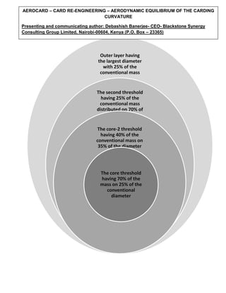
  • 1. Outer layer having the largest diameter with 25% of the conventional mass The second threshold having 25% of the conventional mass distributed on 70% of the diameter The core-2 threshold having 40% of the conventional mass on 35% of the diameter The core threshold having 70% of the mass on 25% of the conventional diameter AEROCARD – CARD RE-ENGINEERING – AERODYNAMIC EQUILIBRIUM OF THE CARDING CURVATURE Presenting and communicating author: Debashish Banerjee- CEO- Blackstone Synergy Consulting Group Limited, Nairobi-00604, Kenya (P.O. Box – 23365) db@blackstonesynergy.com
  • 2. The analysis of the core component shall reveal the following features: 1. Circular cross-section implies a uniform distribution of the discrete particles that constitute the mass distribution map. 2. The packing of 70% of the original conventional mass in just 25% of the diameter brings in greater compactness with so much so additional discrete particles crowding either side of the central axis that makes the cylinder of the core concentric under stress with higher rotational torque 3. The centrifugal force originating from the core shall be determined by the linear velocity; approximately a multiple of 13.46 on the conventional cylinder. The kinetic energy transmitted along the radial direction outwards shall be phenomenal (1200 % +); an intense energy at that. 4. The function y describing energy transmitted outwards shall be denoted by y=f(x1) where x1 is determined by the following variables: a) Volume of displaced particles as defined by the torque summation on either side of the axis, b) The entropy in the system as defined by the density of the discrete particles in the mass and CORE-1 STRUCTURAL FUNDAMENTALS THE TORQUE CONFIGURATION AS DEFINED BY THE HIGH PACKING DENSITY AND SMALLER SURFACES PARTITION CHANGES CAUSED WITHIN THE STRUCTURE BY COLLISION PROFILE CONFIGURATIONS A DIFFERENT THRESHOLDS
  • 3. c) The entropy gradient across cut-off lines -1, 2 and 3 in terms of torque stability as determined by the material stability to temperature, collisions energy (high impact-low frequency as well as low impact-high frequency) and specific material strength across the cross-sectional masses. 5. The constant C1 in the equation is defined by the domain strength in terms of spatial configuration of the energy distribution at the interface with the next boundary of the composite. The interface between the core-1 and the core-2 is vital in interpreting the trajectory of the energy line as it permeates through the structure with varying particle density and torque values. There shall be an inherent displacement with an angle  determined by the relative ratio of C1 and C2; both constants being determined by the same conditions as explained above in the respective medium. This deflection in term defines the volume of air displaced and the sharpness of the curvature profile at the edges that change the vector of displacement of energy normal to the impact. ENERGY TRAJECTORY CHANGE CAUSED BY SHIFTING PACKING DENSITIES ANGULAR DEFLECTION 1 AT SHELL-1 & 2 BOUNDARY CORE-1 SHELL CORE-2 SHELL FUNDAMENTAL CHANGES IN STRUCTURAL TORQUE DYNAMICS CAUSE THE ENERGY DEFLECTION IN SPITE OF BASIC CONCAVITY OF THE TWO SURFACES
  • 4. In short, this singular important ratio defines the configuration of the rate of change of the normal since the energy profile is spread over a greater curvature thereby reducing the specific energy at the boundary and aggregating to a slower rate of change of the normalization. This, in turn, spreads the distribution of the drawing vector on the fiber mass at the eventual periphery on a larger cross-section thereby ensuring a gradual separation leading to individualization and higher fiber freedom. Energy deflection at the boundary is the first important derivative of the design proposal. The structural analysis of the core-2 body has the following derivations: 1. The body is concentric with a balanced torque distribution within the coordinates. 2. However, the mass density is lower than in core-1 and consequently, the entropy in the system is higher. 3. The C2 constant is lower in magnitude owing to higher spatial distribution of the energy that is essentially lower in value as well when compared with the core-1 fundamentals. 4. The specific energy at the impacting points along the curvature at the boundary is lower than in core-1 and hence the deflecting angle q2 for the energy shall also be narrower and resulting in an acute angle as compared to q1. 5. Volume of air displaced is a function described in the equation : Equation-2: y2 = f(x2) +C2 where x2 compares with x1 in the following manner: 2 Axes partitioning the torque configuration within the structure TORQUE FUNDAMENTALS ARE SPREAD OVER LOWER PACKING DENSITIES AND ON LARGER SURFACES AS COMPARED TO SHELL OF CORE-1 CORE-2 STRUCTURAL DYNAMICS
  • 5. a) Entropy is higher on account of lower packing density of the material defined by 35% diameter and 40% mass; hence the spatial distribution of discrete particles representing summation of mass is lower (assuming identical metallurgy and cross-sectional particle diameter). b) The entropy of the particles within the colliding medium in a dynamic motion shall be higher causing a larger domain size for the coordinates described by an individual particle – an important derivative in defining the consistency of air volume displaced and the energy transmitted in the radial outwards direction from the composite nucleus. c) Wider domain bounds of the particle coordinates also imply a higher linear curvature of the impact. The third layer of the composite cylinder is fundamentally oval in shape with 80% of the conventional mass distributed in 70% of the diameter. The center of gravity as defined by the coordinates of the composite nucleus is at 33% level of the diameter of the oval structure implying that the structure balance is achieving equilibrium at a lower position thereby lending stability. The equation shall be y3 = f(x3) + C3 The constant C3 shall be different from the preceding ones described by C1 and C2in the following aspects: a) The energy curve shall be periodic in nature and not typically sinusoidal but shall approximate an alternating parabola and an hyperbola with distinctly different SHELL-3: STRUCTURAL ANALYSIS 3 – ACUTE ANGLE ON THE ENERGY PATH DEFLECTION AT THE BOUND
  • 6. amplitudes as determined by the coordinates of the center of gravity and measure of eccentricity angle a as in the illustration. b) The packing density defined by 80% on a spatial distribution of 70% diameter shall reduce entropy significantly and constrain the bounds of x3 thereby ensuring a well defined parabola and an equally sharp outline for the hyperbola; so very vital to ensure a controlled pattern in the air density of the displaced volume and also in the transmitted energy patterns within each revolution of the eccentric bounds. The final phase of the composite has 100% of the mass packed in 100% of the outer diameter of the oval shell; thereby increasing the packing density to minimize particle entropy and controlling the domain bounds as described by the equation: Equation for the outer shell: y4 = f(x4) + C4 The conditions as explained in the equation are: CORE-4: OUTER SHELL STRUCTURE ANGLE OF DEFLECTION FOR THE PARTICLES ANGLE OF ECCENTRICITY
  • 7. a) The CG of the composite nucleus is at 25% of the structural diameter (oval diameter of the outer shell) implying a stabilizing point at a low equilibrium coordinates; in itself a highly stable physical system is assured on a design perspective. b) The bounds are well defined for x4 implying that the parabolic and hyperbolic curves have sharp profiles and that the alternating high air volume is followed by a low displaced volume thereby creating an air draft in the fiber field. c) The measure of eccentricity as described by the angle a2 defines the amplitude of the energy curve moving on an outward radial plane; hence in turn determining the velocities of the displaced air volumes. The above is an illustration that describes the operating layer of the carding zone and the forces constituting the fiber field and has the following features as derivatives: a) The operating layer in the conventional card is thicker and relatively uniform with the normal changes over sharp curve domains. In the design, the operating layer is reduced in thickness by the air draft caused by the alternating parabola and hyperbola of the displacement trajectory of the air particles; a derivative of the oval shape of the shell-3 and 4 of the cylinder composite. b) The shear line is typically shoved up in the reference frame of the operating layer as the wire sharpness depreciates on account of thrust load caused by the build-up of fibers. CONVENTIONAL CARDING CURVATURE Line of shear in the latest models Axis depicting the changes in torque direction for the latest models FIG.1 FIG.2 Line of shear in the proposed design Axis depicting the larger change dynamics for the torque vector direction owing to the impact of specific mass distribution in the staggered cylinder design AERODYNAMIC DESIGN WITH STAGGERED CYKINDER FOR VARYING SPECIFIC MASS DISTRIBUTION
  • 8. In the design, the energy density and the domain bounds as described by x3 and x4 progressively increase the curvature over which the normal changes; in effect the rate of change of the normal is delayed causing the fibers to be gripped strongly on a wider cluster length hereby effectively bringing down the coordinates of the line of shear; the most important derivative of the design. c) The conventional carding zone has the design issue of limited containment of the fiber build-up in the operational layer owing to the transfer dynamics of the fibers to the doffer zones. These are traditionally a function of the relative gap between the cylinder and the doffer, the mutual concentricity of the two rotating elements. The geometric positioning with respect to each other and the wire density of the cylinder with respect to the doffer besides the profile and the tip hardening of the wires. In the design, the oval structure of the shells in the composite and the varying intensities that deflect the energy angles substantially from the original trajectory originating from the nucleus and the significantly decreased rate of change of the normal of the radial outwards energy impact contribute to waves of parabolic and hyperbolic profiles of the displaced air. All of these contribute to a steady draft that contribute to a reduced operational layer thickness, a distinctly lower coordinates for the line of shear and finally the consistent heavy transfer of fibers onto the doffer. The carding intensity of the design is significantly improves; in effect the dynamics of yarn manufacturing is changed for good in a revolutionary manner. The detailed mathematics at the curvature points for describing the surface characteristics of the interfacing points between the shells progressively have been avoided in this paper. That should come up for an expounding while collaborating with the carding OEM. This design is intended to change the dynamics of the yarn engineering process and shall be the singularly most important factor in bringing in value in the textile chain in terms of quality and product economy. Finally, at the concluding stage, Blackstone Synergy intends to reach out to the humanity through these innovations and try and make a difference in the lives of humans affected by the economic crisis.