SlideShare a Scribd company logo
1 of 38
Download to read offline
Empire District Accounts
The Kitchen Meter: 99.84kW The Notch Meter: 99.84kW The Junior High Meter: 31.2kW
Account #310966-34-026 Account #310966-34-713 Account #310966-34-698
Meter #91060229 Meter #70060004 Meter #00201119
Jurisdiction: City of Greenfield No Permit, No Inspection
Greenfield High School & Junior High
410 College St., Greenfied, MO 65661
Zachary Wilson: 417-637-5321 x335
230.88 kW
ZacharyWilson,GreenfieldR-1VSchoolDistrict
HighSchool&JuniorHigh
410CollegeStreet
Greenfield,MO65661
417-637-5321x335
zwilson@greenfield.k12.mo.us
Missouri Sun Solar, LLC
260 Old State Rd.
Ellisville, MO 63021
PVGI-1
Designer
D. Hults
Reviewer
B. Arthur
General Information
Grid Tied PV System
Date
2016-06-27
Scale
NTS
System Specifications, Main Components: Roof Mount
Item Manufacturer Model Quantity Size: In Array Area: Sqft Weight: Lbs Array Weight: Lbs Watts
Panel Module Q-Cell Q-Pro.G4 260 888 65.7 x 39.4 x 1.38 17,212 41.89 37869 260
Inverter 1 Fronius Primo 10.0-1 1 20.1 x 28.5 x 8.9 82.5 1000
Inverter 2 Fronius Primo 8.2-1 2 16.9 x 24.7 x 8.1 47.29 8200
Inverter 3 Huwaei SUN2000-30KTL-US 6 21.7×30.3×10.6 121 30000
Attachment S-5! S-5-U Clamp MINI
Ballasted Racking Dynoraxx Evolution FR Roof System
Roof Specifications Site Specifications Array Specifications
Steel Truss or Metal/Wood Framing to Code. Occupancy: Educational Design Low Temp: '-20° F
Flat Roof, Gravel Topped with Ballasted Racking Building Size: 1 & 2 Story Areas Design High Temp: 110° F
Metal Roof Standing Seam with Fixed Racking Design Wind Speed: 90 MPH Azimuths: 180°
Flat Membrane Roof - NO USE Exposure Category: B Tilt Angle: 10° in Ballasted Array, flush Mount with Roof on Metal Roof
Ground Snow Load: 20 PSF
Table of Contents
PVGI-1 General Information
PVAL-2 Array Layout
PVSL-3 String Layout
PVMN-4 Materials & Notes
PVED-5 Electrical Diagram
Attachments
1) Panel Data
2) Panel Warranty
3) Inverter 1 & 2 Data
4) Inverter 1 & 2 Warranty
5) Inverter 3 Data
6) Inverter 3 Warranty
7) Transformer Data
8) AC Disconnect 1 P
9) AC Disconnect 3P
10) Attachment Data
Scope of Work
1)
Scope includes the
installation of a Photovoltaic
Array in a Roof Mounted
Racking System including
related Hardware and
Electrical Equipment
2)
All Electricity generated is
for consumption on the site
3)
Permit shall include labor of
running of Electrical
Conduit(s), installation of
new Electrical Equipment,
and Electrical Connection to
the Existing Site Building
4)
The Project does not include
the installation of Batteries
1
1
2
3
2 3
Revision 6-27-16; DH: As-Built 2
M
D
Missouri Sun Solar, LLC
260 Old State Rd.
Ellisville, MO 63021
PVAL-2
Designer
D. Hults
Reviewer
B. Arthur
Array Layouts
ZacharyWilson,GreenfieldR-1VSchoolDistrict
HighSchool&JuniorHigh
410CollegeStreet
Greenfield,MO65661
417-637-5321x335
zwilson@greenfield.k12.mo.us
Date
2016-06-27
Scale
NTS
N
M D
M D
"The Notch": Exterior East Wall of Building
Existing Meter: #70060004
3-Phase Service, 120/208 V
Existing Service Panels: 400A, 600A, 800A
Solar AC Disconnect
Solar Transformer: 480V - 240V
Solar Subpanel
Solar Inverters: Huwaei SUN2000-30KTL (x3)
Solar Panel Load: 388 Panels: 99.84 kW
Location of Arrays: Sloped Metal Rooftop Directly East of Meter
Solar Panel Module: Q-Cell Q-Pro.G4 260
"The Kitchen": Exterior North Wall of Building
Existing Meter: #91060229
3-Phase Service, 120/208 V
Existing Service Panel: 400A
Solar AC Disconnect
Solar Transformer: 480V - 208V
Solar Subpanel
Solar Inverters: Huwaei SUN2000-30KTL (x3)
Solar Panel Load: 388 Panels: 99.84 kW
Location of Arrays: Flat Gravel Rooftops Directly South of Meter
Solar Panel Module: Q-Cell Q-Pro.G4 260
"The Junior High": Exterior South Wall of Building
Existing Meter: #00201119
1-Phase Service, 240V
Existing Service Panel: 400A
Solar AC Disconnect
Solar Subpanel
Solar Inverters: Fronius Primo 8.2-1 (2x) and 6.0-1 (x2)
Solar Panel Load: 120 Panels: 31.2kW
Location of Arrays: Sloped Metal Roof Directly Above Meter
Solar Panel Module: Q-Cell Q-Pro.G4 260
School Entrances
DO NOT TOUCH
MEMBRANE ROOF DO NOT TOUCH
MEMBRANE ROOF
Revision 6-27-16; DH: As-Built 2
M
D
M D
Missouri Sun Solar, LLC
260 Old State Rd.
Ellisville, MO 63021
PVAL-2
Designer
D. Hults
Reviewer
B. Arthur
Array Layouts
ZacharyWilson,GreenfieldR-1VSchoolDistrict
HighSchool&JuniorHigh
410CollegeStreet
Greenfield,MO65661
417-637-5321x335
zwilson@greenfield.k12.mo.us
Date
2016-06-27
Scale
NTS
N
DO NOT TOUCH
MEMBRANE ROOF
M D
Junior High School Arrays: 120 Panels: 31.2kW
Inverters: Fronius Primo 10.0-1 4 Strings of 12
(2x) Fronius Primo 8.2-1 3 Strings of 12
The Kitchen: 388 Panels: 99.84kW
Inverters: (3x) Huwaei SUN2000-30KTL
The Notch: 388 Panels: 99.84kW
Inverters: (3x) Huwaei SUN2000-30KTL
INVS
INVS
INVS
# Panels: String Color
23:
22:
21:
20:
19:
18:
High School Arrays: 776 Panels: 199.68kW
1
2
12
11
10
98
7
6
5
4
3
3
2
1
12 11
98 10
7
6
4
5
15
16
17 18
14 13
13
15
16 17 18
14
15
1617
18
14
5
4
3
1
2
10 9
8
6
7
13
12
11
15
16
1718
14
5
4
3
1
2
10
9 8
6
7
13
1211
19
19
1
1
2
3
4
5
6 7
9
10
8
2
3
4
5
6
7
9
10
8
Revision 6-27-16; DH: As-Built 2
PVSA-4
Missouri Sun Solar, LLC
260 Old State Rd.
Ellisville, MO 63021
Designer
D. Hults
Reviewer
B. Arthur
String Assignment
ZacharyWilson,GreenfieldR-1VSchoolDistrict
HighSchool&JuniorHigh
410CollegeStreet
Greenfield,MO65661
417-637-5321x335
zwilson@greenfield.k12.mo.us
Date
2016-06-21
Scale
NTS
Junior High: 120 Panels: 31.2kW
Fronius #2 Primo 8.2-1 Fronius#2 Primo 8.2 -1 Fronius #1 Primo 10.0-1
1. 12 4. 12 7. 12 9. 12
2. 12 5. 12 8. 12 10. 12
3. 12 6. 12
36 Panels 36 Panels 48 Panels
The Kitchen: 388 Panels: 99.84kW
Huwaeii 30kW #3.1 Huwaeii 30kW #3.2 Huwaeii 30kW #3.3
1. 22 7. 22 14. 19
2. 22 8. 20 15. 21
3. 19 9. 20 16. 21
4. 22 10. 20 17. 21
5. 22 11. 20 18. 21
6. 22 12. 19 19. 21
13. 18
129 Panels 139 Panels 124 Panels
The Notch: 388 Panels: 99.84kW
Huwaeii 30kW #3.1 Huwaeii 30kW #3.2 Huwaeii 30kW #3.3
1. 20 7. 23 13. 21
2. 19 8. 23 14. 21
3. 18 9. 23 15. 21
4. 23 10. 23 16. 21
5. 23 11. 19 17. 19
6. 23 12. 23 18. 21
126 Panels 134 Panels 124 Panels
Revision 6-27-16; DH: As-Built 2
DC
AC
3DC
AC
3DC
AC
DC
AC
DC
AC
3DC
AC
3DC
AC
WireSchedule
TagWireTypeGroundConduitLength
A#10AWGTHHNCu#10THHN1-1/4"EMT200'
B#8AWGTHHNCu#6THHN3/4"EMT20'
C#6AWGTHHNCu#6THHN3/4"EMT20'
D#2AWGTHHNCu#1THHN1-1/2"Sealtight20'
E250KCMICu#3THHN2-1/2"Sealtight20'
PVED-5
Missouri Sun Solar, LLC
260 Old State Rd.
Ellisville, MO 63021
Designer
D. Hults
Reviewer
B. Arthur
Electrical Diagram
ZacharyWilson,GreenfieldR-1VSchoolDistrict
HighSchool&JuniorHigh
410CollegeStreet
Greenfield,MO65661
417-637-5321x335
zwilson@greenfield.k12.mo.us
Date
2016-06-27
Scale
NTS
All Equipment Clearly Labeled with Descriptive Signage
Roof
Existing
Electrical
Panel Loads
888 Q-Cell 260W Solar Panels
Module Q.Pro-G4 260
Inverters: #1 Fronius Primo 10.0-1 (x1)
#2 Fronius Primo 8.2-1 (x2)
#3 Huwaei 2000-30TKL-US (x6)
M
To Utility
Rex Custom Transformer
480-240Delta, 125kva
A
48 Panels
36 Panels
36 Panels
Exterior Wall of Buildings or Electrical Poles Adjacent to the Buildings
126 Panels
134 Panels
124 Panels
124 Panels
129 Panels
139 Panels
TheKitchen:99.84kWTheNotch:99.84kWJr.HighSchool:31.2kW
70A
Subpanel
225A / 240V
Fused AC Disconnect
Square -D D325NRB
400A / 240V
175A Type R
Fuses
50A
50A
Fused AC Disconnect
Square -D H365NR
400A / 600V
Fused AC Disconnect
Square -D H365NR
400A / 600V
To Utility
To Utility
C
B
A
C
B
A
C
B
A
50A
70A
50A
M
M
Strings 13 - 18
Strings 7 - 12
Strings 1 - 6
Strings 13 - 18
Strings 7 - 12
Strings 1 - 6
Strings 7 - 10
Strings 1 - 3
Strings 4 - 6
Linetap: Burndy 250-10
One Sided Unitap
In Existing Enclosure
Existing
Electrical
Panel Loads
Existing
Electrical
Loads
C
B
A
C
B
A
C
B
A
50A
70A
50A
Subpanel
400A / 600V
Subpanel
400A / 600V REX Custom Transformer
480V - 208V, 125kva
Jr. High Meter #00201119
Existing Meter Combo Box
1P, 400A / 240V
HS Notch Meter #70060004
3P, 400A / 208Delta
HS Kitchen Meter #91060229
3P, 600A / 208V
A
A
A
A
A
A
A
A
B
B
B
C
B
B
C
D
D E E
E E
DD
INV3.2
INV3.2
*
*
INV3.3
INV3.1
INV3.3
INV3.1
Revision 6-27-16; DH: As-Built 2
*
*
Existing
Wire
Existing Disconnect
800A / 600VPOI on Open Lug of Disconnect
Existing
Wire
Existing
Wire
Existing MDP
600A / 600V
350A
TP
350A Type R
Fuses
350A Type R
Fuses
Q.PRO BFR-G4 255-265
1
	 APT test conditions: Cells at -1000 V
against grounded, with conductive me-
tal foil covered module surface, 25 °C,
168 h
2
	 See data sheet on rear for further
information.
POLYCRYSTALLINE SOLAR MODULE
The new Q.PRO BFR-G4 is the result of the continued evolution of our
Q.PRO family. Thanks to improved power yield, excellent reliability, and
high-level operational safety, the new Q.PRO BFR-G4 generates electricity
at a low cost (LCOE) and is suitable for a wide range of applications.
THE IDEAL SOLUTION FOR:
Rooftop arrays on
commercial / industrial
buildings
Ground-mounted
solar power plants
Rooftop arrays on
residential buildings
LOW ELECTRICITY GENERATION COSTS
Higher yield per surface area and lower BOS costs thanks to
higher power classes and an efficiency rate of up to 16.2 %.
INNOVATIVE ALL-WEATHER TECHNOLOGY
Optimal yields, whatever the weather with excellent low-light
and temperature behavior.
ENDURING HIGH PERFORMANCE
Long-term yield security with Anti-PID Technology1
,
Hot-Spot-Protect and Traceable Quality Tra.Q™.
LIGHT-WEIGHT QUALITY FRAME
High-tech aluminum alloy frame, certified for
high snow (5400 Pa) and wind loads (4000 Pa).
MAXIMUM COST REDUCTIONS
Up to 10 % lower logistics costs due to higher module capacity per box.
SAFE ELECTRONICS
Protection against short circuits and thermally induced power losses
due to breathable junction box and welded cables.
A RELIABLE INVESTMENT
Inclusive 12-year product warranty and 25-year
linear performance guarantee2
.
ANTI PID TECHNOLOGY
(APT)
HOT-SPOT PROTECT
(HSP)
TRACEABLE QUALITY
(TRA.Q™)
YIELD SECURITY
151 modules tested
Best polycrystalline
solar module 2013
Q.PRO-G2 235
MOD:27898 photon.info/laboratory



Quality Tested
ID. 40032587
high reliability
low degradation
frequent
product surveillance
Missouri Sun Solar: Greenfield High School & Jr. High, 230.88kW 1) Panel Data
MECHANICAL SPECIFICATION
Format 65.7 in × 39.4 in x 1.26 in (including frame)
(1670 mm × 1000 mm × 32 mm)
Weight 41.45 lb (18.8 kg)
Front Cover 0.13 in (3.2 mm) thermally pre-stressed glass with anti-reflection technology
Back Cover Composite film
Frame Black anodized aluminum
Cell 6 × 10 polycrystalline solar cells
Junction box 4.33 in × 4.53 in × 0.9 in (110 mm × 115 mm × 23 mm),
Protection class IP67, with bypass diodes
Cable 4 mm² Solar cable; (+) ≥ 39.37 in (1000 mm), (-) ≥ 39.37 in (1000 mm)
Connector Tyco Solarlok PV4, IP68
NA
DETAIL A 0.630" (16 mm)
0.335" (8.5 mm)
0.965" (24.5 mm)
Junction bo×
Product label
38.58" (980 mm)
65.7" (1670 mm)
4 × Fastening points (DETAIL A)
Cable with
connectors
Frame
5.90" (150
mm)
39.4" (1000 mm)
37.44" (951 mm)
1.26" (32 mm)
8 × Drainage holes
6 × Grounding points ø 0.177" (4.5 mm)
39.37" (1000 mm)
Q CELLS PERFORMANCE WARRANTY PERFORMANCE AT LOW IRRADIANCE
IRRADIANCE [W/m²]
RELATIVEEFFICIENCY[%]
100 200 300 400 500 600 700 800 900 1000
105
100
95
90
85
80
Irradiance [W/m²]
Relativeefficiency[%]
PROPERTIES FOR SYSTEM DESIGN
Maximum System Voltage VSYS
[V] 1000 (IEC) / 1000 (UL) Safety Class II
Maximum Series Fuse Rating [A DC] 20 Fire Rating C / TYPE 1
Max Load (UL)2
[lbs/ft2
] 75 (3600 Pa) Permitted module temperature
on continuous duty
− 40 °F up to +185 °F
(− 40 °C up to +85 °C)
Load Rating (UL)2
[lbs/ft2
] 55.6 (2666 Pa) 2
see installation manual
QUALIFICATIONS AND CERTIFICATES PACKAGING INFORMATION
Number of Modules per Pallet 32
Number of Pallets per 53' Container 32
Number of Pallets per 40' Container 26
Pallet Dimensions ( L × W × H ) 68.7 in × 45.0 in × 46.0 in
(1745 × 1145 × 1170 mm)
Pallet Weight 1323 lb (651 kg)
NOTE: Installation instructions must be followed. See the installation and operating manual or contact our technical service department for further information on approved installation and use
of this product.
EN
RELATIVEEFFICIENCY
COMPAREDTONOMINALPOWER[%]
100
95
90
85
80
75
155 25200 10
YEARS
97
Q CELLS
Industry standard for tiered warranties*
Industry standard for linear warranties*
*
Standard terms of guarantee for the 10 PV companies
with the highest production capacity in 2014 (as at: September 2014)
Certified
UL 1703
(254141)
TEMPERATURE COEFFICIENTS
Temperature Coefficient of ISC α [% / K] + 0.04 Temperature Coefficient of VOC β [% / K] − 0.30
Temperature Coefficient of PMPP γ [% / K] − 0.41 Normal Operating Cell Temperature NOCT [°F] 113 ± 5.4 (45 ± 3 °C)
UL 1703; VDE Quality Tested; CE-compliant;
IEC 61215 (Ed.2); IEC 61730 (Ed.1) application class A
Specificationssubjecttotechnicalchanges©HanwhaQ CELLSGmbHQ.PROBFR-G4_2015-04_Rev03_NA
At least 97 % of nominal power during
first year. Thereafter max. 0.6 % degra-
dation per year.
At least 92 % of nominal power after
10 years.
At least 83 % of nominal power after
25 years.
All data within measurement tolerances.
Full warranties in accordance with the
warranty terms of the Q CELLS sales
organisation of your respective country.
The typical change in module efficiency at an irradiance of 200 W/m² in relation
to 1000 W/m² (both at 25 °C and AM 1.5 G spectrum) is -2 % (relative).
Hanwha Q CELLS USA Corp.
300 Spectrum Center Drive, Suite 1250, Irvine, CA 92618, USA | TEL +1 949 748 59 96 | EMAIL q-cells-usa@q-cells.com | WEB www.q-cells.us
ELECTRICAL CHARACTERISTICS
POWER CLASS 255 260 265
MINIMUM PERFORMANCE AT STANDARD TEST CONDITIONS, STC1
(POWER TOLERANCE +5 W /- 0 W)
Minimum
Power at MPP2
PMPP [W] 255 260 265
Short Circuit Current* ISC [A] 9.07 9.15 9.23
Open Circuit Voltage* VOC [V] 37.54 37.77 38.01
Current at MPP* IMPP [A] 8.45 8.53 8.62
Voltage at MPP* VMPP [V] 30.18 30.46 30.75
Efficiency2
η [%] ≥ 15.3 ≥ 15.6 ≥ 15.9
MINIMUM PERFORMANCE AT NORMAL OPERATING CONDITIONS, NOC3
Minimum
Power at MPP2
PMPP [W] 188.3 192.0 195.7
Short Circuit Current* ISC [A] 7.31 7.38 7.44
Open Circuit Voltage* VOC [V] 34.95 35.16 35.38
Current at MPP* IMPP [A] 6.61 6.68 6.75
Voltage at MPP* VMPP [V] 28.48 28.75 29.01
1
1000 W/m², 25 °C, spectrum AM 1.5 G	 2
Measurement tolerances STC ± 3 %; NOC ± 5 %	 3
800 W/m², NOCT, spectrum AM 1.5 G	 * typical values, actual values may differ
Missouri Sun Solar: Greenfield High School & Jr. High, 230.88kW
SCOPE
The following warranty terms and conditions apply exclusively to
Q CELLS photovoltaic modules of the following types:
•	 Q.PRO-G4, Q.PRO BFR-G4, Q.PRO BLK-G4, Q.PRO-G4/SC,
Q.PLUS-G4
•	 Q.PEAK-G3, Q.PEAK BLK-G3
•	 Q.PRO-G3, Q.PRO BFR-G3, Q.PLUS-G3
•	 Q.PRO L, Q.PRO L-G2, Q.PRO L-G3, Q.PRO L-G3.1, Q.PRO L-G4,
Q.PLUS L-G4
manufactured by Q CELLS, sold and installed within the United States,
Canada, Mexico, Panama and Costa Rica and which bear the manufac-
turer’s label of Q CELLS.
Warrantor is the Hanwha Q CELLS GmbH, OT Thalheim, Sonnenallee 17-
21, 06766 Bitterfeld-Wolfen, Germany.
The warranty period begins with the initial purchase of the solar modules
by the end customer; the date of invoice is relevant. Any performances of
services under this limited warranty will not extend the warranty period.
12-YEAR PRODUCT WARRANTY
Q CELLS warrants that modules under normal operating conditions and
which are installed, used and serviced in accordance with the relevant prod-
uct information, particularly the installation instructions, will not show any
material defects or workmanship defects for a period of 12 (twelve) years af-
ter initial purchase. In the event that a module has a defect covered by this
warranty (case of warranty), Q CELLS undertakes to remedy the situation
within a reasonable time and may choose, at its sole discretion, whether to
repair the defect or to supply a module which is free of defects. In no event
shall Q CELLS be liable for any indirect, consequential or extra-contractual
damages.
25-YEAR LINEAR PERFORMANCE WARRANTY2
In addition, Q CELLS provides the following performance warranty for
modules which are installed in accordance with the relevant module
specifications and other product documentations.
In the first year after the initial purchase the crystalline modules will pro-
duce a minimum power output of at least 97 % specified in the module
data sheet. From the 2nd year onwards and for a duration of 24 years the
crystalline modules will have a yearly maximum decrease (degradation) of
power of not more than 0.6 %, i.e. after 25 years the crystalline module
will have a minimum power output of at least 83 % of the minimum
power output specified in the module data sheet.
All power data refers to measurements under the STC Standard Test Con-
ditions applicable at the beginning of this warranty. The STC Standard
Test Conditions are customary standardized basic conditions for the mea-
surement of the power of solar modules. The currently valid Standard Test
Conditions are defined in the IEC standards EN 61215 and 60904-3.
In the event of a claim being made under the warranty Q CELLS shall
be free to decide at its own discretion to make up the difference to the
guaranteed power output by refinishing the system by replacing the mod-
ule or by supplying additional modules as described in “warranty claims
and entitlements” or by repaying the purchase price of the modules or
by reducing the purchase price in proportion of the actual power to the
guaranteed power, taking into account an annual depreciation rate on
the original purchase price as evidenced by the invoice produced by the
customer. Other payments of whatever nature, including, but not limited
to the compensation for expenses or for related damages, shall not be
covered by the warranty.
WARRANTY TERMS AND CONDITIONS FOR CRYSTALLINE PHOTOVOLTAIC MODULES
FROM HANWHA Q CELLS GMBH
Valid from March 1st, 2015
SUMMARY OF LIMITED WARRANTY TERMS AND CONDITIONS
12 YEARS PRODUCT WARRANTY
	 For material defects or processing defects.
	 HOT-SPOT PROTECT and ANTI PID TECHNOLOGY1
.
25 YEARS LINEAR PERFORMANCE WARRANTY
	 At least 97 % of the nominal power within the first year. Thereafter, decrease of the power output will not exceed 0.6 % p. a.
	 Minimal nominal rated power after 25 years at least 83 %.
Dear Customer,
You have made an excellent choice in purchasing quality
Q CELLS modules manufactured by the Hanwha Q CELLS GmbH
(thereafter, Q CELLS), OT Thalheim, Sonnenallee 17-21, 06766
Bitterfeld-Wolfen, Germany. The photovoltaic modules you have
purchased have been manufactured with great care and have
undergone a final functional test. If, however, a module shows a
material defect or a processing defect or suffers a loss of power
during the warranty period, we provide the following Q CELLS
limited warranty, subject to the terms and conditions hereof.
1
	 HOT-SPOT PROTECT: The modules are safe against backside destruction caused by Hot-Spot effects due to partial shading of modules.
	 ANTI PID TECHNOLOGY: The modules are safe against potential-induced degradation in accordance to the test criteria: Cells at -1000 V against grounded, with conductive metal 	
	 foil covered module surface, 25 °C, 168 h
2
	 All data referering to the module power / performance are within the framework of the power tolerances as defined in the respective data sheet.
Missouri Sun Solar: Greenfield High School & Jr. High, 230.88kW 2) Panel Warranty
EXCLUSIONS FROM THE LIMITED PRODUCT AND PERFORMANCE WARRANTIES
Irrespective of contributory root causes, this limited warranty does not
cover the following cases:
•	 incorrect usage, misuse, modifications of the modules or incorrect han-
dling including usage or handling in any manner that is contrary to the
instructions provided in this regard by Q CELLS for the customer un-
der any module specifications and/or product documentation for such
product;
•	 errors relating to the transport, storage, installation, or use, e.g. through
non-compliance with installation and operating manual or any other in-
structions issued by Q CELLS for the customer in this regard at the time
of purchase, incorrect static, etc.;
•	 incorrect system configuration, e.g. installation of mutually incompat-
ible modules, as well as inadequate system design, particularly (but not
limited to) incompatible inverter;
•	 incorrect or inadequate servicing or maintenance work (cf. information
set out in the relevant product information);
•	 usage for unusual purposes or purposes specifically categorized  as be-
ing unsuitable for usage of the product, in unusual circumstances or in
unsuitable ambient conditions not conforming to the product specifica-
tions (as set out in the module data sheet applicable to the modules
in any given case) or not complying with the installation and operating
instructions;
•	 damage caused by extreme environmental sources of impact, including,
but not limited to such as acid rain, saline air, pollution of any kind as
well as fire, explosion, smoke or charring;
•	 damage caused by acts of nature or acts of god, including, but not
limited to lightning, hail, frost, snow, storms, tidal waves, floods, earth-
quakes, typhoons, volcanic eruptions, ground motions, earth fissures or
landslides;
•	 damage caused directly or indirectly by acts of violence or intervention
by third parties or external forces, such as misadventure, riots, war, in-
surrection, communal violence or vandalism as well as damage caused
by game animals and other forces majeures;
•	 damage to the photovoltaic system in which the modules are installed,
most notably caused by factors, including, but not limited to such as
voltage fluctuations, power peaks, excess current, power failure poor
electrical or mechanical engineering work, or other faults occurring in a
power supply system with or without mains connection, whether or not
such faults in the power supply system was contributed to by any act or
omission of the customer;
The following cases are also excluded from the warranty:
•	 the Q CELLS modules are modified or used in processes involving other
products without obtaining written consent from Q CELLS;
•	 scratches, marks, mechanical wear, rust, mold, degradation, discolor-
ation and other changes which occur after the delivery of the modules
by Q CELLS but which do not result in any adverse effect on the me-
chanical stability of the product or a reduction of performance which
exceeds the levels set out in the performance warranty;
•	 Inadequate system size, in particular the incorrect selection of the AC
power inverter;
•	 The serial number or product label has been removed, changed, deleted
or made unrecognizable or it is no longer clearly distinguishable and leg-
ible for other reasons beyond Q CELLS’ reasonable control and therefore
it is not possible to conclusively identify the modules.
This limited warranty does not apply to modules which are used on mobile
carriers such as motor vehicles or ships. The same applies to the usage
of modules in high snow loads where the conditions of use exceed the
specifications set out in the relevant product information.
As part of the limited warranty there is no right to compensation for or the
reimbursement of costs for dismantling, installation or replacement, loss
of yield or other indirect damages.
In no event shall Q CELLS be liable for any indirect, consequential or
extra-contractual damages.
CLAIMS UNDER THE LIMITED PRODUCT AND PERFORMANCE WARRANTY /
NOTIFICATION OF DEFECTS
The supplied modules must be checked for visible defects when they are
purchased. Any defects discovered during this process must be reported
immediately to the vendor, if any, who shall be the first point of contact
for the end customer or photovoltaic system owner. In case there is no
other vendor, the first point of contact shall be Hanwha Q CELLS USA
Corp. (with contact details as referred to below), who then shall immedi-
ately inform Q CELLS accordingly.
If the defects are not reported immediately to the vendor or Hanwha Q
CELLS USA, the warranty becomes discharged. Any warranty claim must
be reported to the vendor or Hanwha Q CELLS USA Corp. prior to the end
of the applicable warranty period and no later than 30 days after discover-
ing the breach of warranty.
Please contact the vendor or Hanwha Q CELLS USA Corp. first in writing
or electronically. Contact information, the required data and the proce-
dure of the complaint process are described in the RMA process docu-
ment (Return Merchandise Authorization) available at Hanwha Q CELLS
USA Corp..
If you have any questions please contact your seller or, as the case may
be, Hanwha Q CELLS USA Corp. at the contact details referred to below
or Q CELLS at the following e-mail address: service@q-cells.com.
We ask for our customers’ understanding that Q CELLS cannot accept any
unauthorized return shipments of modules and the company will not take
delivery of such items.
PERFORMANCE OF THE WARRANTY SERVICES
•	 In all cases, Q CELLS shall have the choice, at its sole and absolute
discretion, as to how warranty claims are settled. Q CELLS may use the
services of a customer service unit or a service partner for this purpose
as deemed fit by Q CELLS. Additional agreements may be made in con-
tract form in a service level agreement with Q CELLS.
•	 Q CELLS shall pay the costs of a technical inspection and transport
in the event that the warranty claim is confirmed by such inspection.
Otherwise the claimant shall be charged with these costs.
•	 Q CELLS shall only be liable under the limited performance warranty if
and only in the situation wherein the performance (i.e. module power)
measured by Q CELLS under the STCs (Standard Test Conditions) does
not meet the performance.
•	 The Customer must comply with the Return Merchandise Authorization
(RMA) issued by Q CELLS.
Missouri Sun Solar: Greenfield High School & Jr. High, 230.88kW
Subjecttomodifications.©HanwhaQ CELLSWarranty_terms_modules_US_2015-03_Rev17_NA
Hanwha Q CELLS USA Corp.
300 Spectrum Center Drive, Suite 1250, Irvine, CA 92618, USA | TEL +1 949 748 59 96 | EMAIL q-cells-usa@q-cells.com | WEB www.q-cells.us
• The Customer must submit the original receipt or invoice which bears
the date of purchase, the serial numbers of the relevant modules, and
the name of the authorized seller.
•	 The modules sent to Q CELLS in the course of the RMA process shall
remain the property of the customer until any inspection has been com-
pleted and Q CELLS provides a replacement or refund. If under the
warranty a replacement or refund takes place, the ownership of these
modules passes to Q CELLS.
•	 Any repaired, replacement or additionally supplied module hereunder
will be warranted only for the remainder of the original warranty period
applicable to the original module.
•	 Q CELLS hereby assures that any replacement parts used for the recti-
fication of defects shall be of equivalent or better quality, and that they
shall be covered by the product warranty for the remaining portion of the
original warranty period.
•	 If Q CELLS supplies replacement or additional modules on the basis
of these warranty terms and conditions the replacement or additional
modules may be of a similar or equivalent type from the product range
available at the time of the claim as long as they are suitable for the
intended purpose and if the original module type is no longer available.
•	 In the event of glass breakage a static calculation to verify the sub-
structure is an additional prerequisite for exercising a claim under the
limited warranty.
•	 If a module is sold as a consumer product, to the extent required by
applicable law, if Q CELLS cannot remedy the defective module after
reasonable attempts, Q CELLS may elect to receive a replacement mod-
ule or (i) with respect to the limited product warranty, a refund of the
purchase price after taking into account an annual 4 % depreciation
rate or (ii) with respect to the limited performance warranty, the lesser
of the amount of such refund or a reduction of the purchase price in the
same proportion as the power shortfall bears to the guaranteed power.
WARRANTY LIMITATIONS
THE EXCLUSIVE WARRANTY REMEDIES SET FORTH HEREIN ARE
THE SOLE REMEDIES FOR ANY BREACH OF WARRANTY BY Q CELLS.
THE EXPRESS WARRANTIES SET FORTH HEREIN ARE IN LIEU OF
ALL OTHER WARRANTIES, WHETHER EXPRESS, IMPLIED, OR STATU-
TORY, REGARDING ANY MODULES SUPPLIED BY Q CELLS, INCLUD-
ING ANY IMPLIED WARRANTIES OF MERCHANTABILITY, FITNESS
FOR A PARTICULAR PURPOSE OR NON-INFRINGEMENT; PROVIDED,
THAT IF A MODULE IS SOLD AS A CONSUMER PRODUCT, TO THE
EXTENT REQUIRED BY APPLICABLE LAW, ANY IMPLIED WARRANTIES
OF MERCHANTABILITY, FITNESS FOR A PARTICULAR PURPOSE OR
NON-INFRINGEMENT ARE LIMITED TO THE PERIODS OF THE LIMIT-
ED PRODUCT AND LIMITED PERFORMANCE WARRANTIES SET FORTH
ABOVE, OR SUCH SHORTER PERIOD(S) AS REQUIRED BY APPLICA-
BLE LAW. THIS LIMITED WARRANTY GIVES CUSTOMERS SPECIFIC
LEGAL RIGHTS, AND CUSTOMER MAY ALSO HAVE OTHER RIGHTS
WHICH VARY FROM STATE TO STATE. Q CELLS IS NOT RESPONSIBLE
OR LIABLE IN ANY WAY FOR DAMAGE OR INJURY TO PERSONS OR
PROPERTY, OR FOR OTHER LOSS OR INJURY RESULTING FROM ANY
CAUSE WHATSOEVER, ARISING OUT OF OR RELATED TO ANY MOD-
ULES SUPPLIED BY Q CELLS.
IN NO EVENT WILL Q CELLS BE LIABLE FOR ANY LOSS OF REVENUE,
OR CONSEQUENTIAL, INDIRECT, EXEMPLARY, SPECIAL OR INCIDEN-
TAL DAMAGES, ARISING FROM OR RELATING TO THIS WARRANTY OR
ANY MODULE OR ANY REPLACEMENT OR ADDITIONAL MODULE SUP-
PLIED BY Q CELLS HEREUNDER EVEN IF AWARE OF THE POSSIBILITY
OF SUCH DAMAGES. Q CELLS’ TOTAL LIABILITY ARISING FROM OR
RELATING TO THIS WARRANTY, WHETHER IN CONTRACT OR TORT OR
OTHERWISE, WILL NOT EX CEED THE AMOUNT PAID TO Q CELLS OR
ITS SUBSIDIARIES FOR THE MODULE WHICH IS THE SUBJECT OF
THE CLAIM(S) OR DISPUTE(S). SOME STATES DO NOT ALLOW THE
EXCLUSION OR LIMITATION OF INCIDENTAL OR CONSEQUENTIAL
DAMAGES, SO THE ABOVE LIMITATION OR EXCLUSION MAY NOT AP-
PLY TO CUSTOMER.
TRANSFER OF LIMITED WARRANTY
This limited warranty is transferable with respect to any module to a new
owner of the entire photovoltaic system in which such module is originally
installed, provided that such system remains intact in its original place of
installation. This warranty may not otherwise be assigned or transferred.
GENERAL
If any provision of these limited warranty terms and conditions is held to
be invalid, illegal or unenforceable in any respect, such provision will be
changed and interpreted to accomplish the objectives of such provision
to the greatest extent possible under applicable law and the remaining
provisions will continue in full force and effect.
These warranty terms and conditions shall be exclusively governed by
German law. The UN Convention on Contracts for the International Sale
of Goods shall not apply.
All statutory warranty rights which you have in case of a material defect or
a legal defect against your seller in accordance with the applicable sales
law are not restricted by this warranty. You can exercise your statutory
warranty rights against the seller regardless of whether there is a warranty
case or whether you exercise a claim to us under this warranty.
Missouri Sun Solar: Greenfield High School & Jr. High, 230.88kW
/ Perfect Welding / Solar Energy / Perfect Charging
/ With power categories ranging from 3.8 kW to 15.0 kW, the transformerless Fronius Primo is the ideal compact
single-phase inverter for residential applications. The sleek design is equipped with the SnapINverter hinge mounting
system which allows for lightweight, secure and convenient installation and service. The Fronius Primo has several
integrated features that set it apart from competitors including dual powerpoint trackers, high system voltage, a wide
input voltage range, Wi-Fi* and SunSpec Modbus interface for seamless monitoring and datalogging, Arc Fault Circuit
Interruption (AFCI), and Fronius’ online and mobile platform Fronius Solar.web. The Fronius Primo is designed to
adjust to future standards, offering a complete solution to code restrictions and technical innovations of tomorrow. It
also works seamlessly with the Fronius Rapid Shutdown Box for a reliable NEC 2014 solution.
TECHNICAL DATA FRONIUS PRIMO
/ The future of residential solar is here - Introducing the new Fronius Primo.
/ SuperFlex
Design
/ Wi-Fi®*
interface
/ Smart Grid
Ready
/ Arc Fault Circuit
Interruption
/ SnapINverter
mounting system
/ PC board
replacement process
FRONIUS PRIMO
GENERAL DATA FRONIUS PRIMO 3.8 - 8.2 FRONIUS PRIMO 10.0-15.0
Dimensions (width x height x depth) 16.9 x 24.7 x 8.1 in. 20.1 x 28.5 x 8.9 in.
Weight 47.29 lb. 82.5 lbs.
Degree of protection NEMA 4X
Night time consumption < 1 W
Inverter topology Transformerless
Cooling Variable speed fan
Installation Indoor and outdoor installation
Ambient operating temperature range -40 - 131°F (-40 - 55°C) -40 - 140°F (-40 - 60°C)
Permitted humidity 0 - 100 %
DC connection terminals
4x DC+ and 4x DC- screw terminals for copper (solid / stranded /
fine stranded) or aluminum (solid / stranded)
4x DC+1, 2x DC+2 and 6x DC- screw terminals for copper (solid /
stranded / fine stranded) or aluminum (solid / stranded)
AC connection terminals Screw terminals 12 - 6 AWG
Revenue Grade Metering Optional (ANSI C12.1 accuracy)
Certificates and compliance with standards
UL 1741-2010, UL1998 (for functions: AFCI and isolation
monitoring), IEEE 1547-2003, IEEE 1547.1-2003, ANSI/IEEE
C62.41, FCC Part 15 A & B, NEC Article 690, C22. 2 No. 107.1-01
(September 2001) , UL1699B Issue 2 -2013, CSA TIL M-07 Issue 1
-2013
UL 1741-2015, UL1998 (for functions: AFCI, RCMU and isolation
monitoring), IEEE 1547-2003, IEEE 1547.1-2003, ANSI/IEEE
C62.41, FCC Part 15 A & B, NEC Article 690-2014, C22. 2 No.
107.1-01 (September 2001) , UL1699B Issue 2 -2013, CSA TIL
M-07 Issue 1 -2013
PROTECTIVE DEVICES STANDARD WITH ALL PRIMO MODELS
AFCI & 2014 NEC Ready Yes
Ground Fault Protection with Isolation Monitor
Interrupter
Yes
DC disconnect Yes
DC reverse polarity protection Yes
N
W
S
E
INTERFACES STANDARD WITH ALL PRIMO MODELS
Wi-Fi*/Ethernet/Serial Wireless standard 802.11 b/g/n / Fronius Solar.web, SunSpec Modbus TCP, JSON / SunSpec Modbus RTU
6 inputs or 4 digital inputs/outputs External relay controls
USB (A socket) Datalogging and/or updating via USB
2x RS422 (RJ45 socket) Fronius Solar Net, interface protocol
Datalogger and Webserver Included
*The term Wi-Fi® is a registered trademark of the Wi-Fi Alliance.
3) Inverter #1 & 2 DataMissouri Sun Solar: Greenfield High School & Jr. High, 230.88kW
Rev. 11.3.15 USA
/ Perfect Welding / Solar Energy / Perfect Charging
v05 May 2015 EN
Textandimagescorrespondtothecurrentstateoftechnologyatthetimeofprinting.Subjecttomodifications.
Allinformationiswithoutguaranteeinspiteofcarefulediting-liabilityexcluded.Copyright©2011Fronius™.Allrightsreserved.
Further information about all Fronius products and our global sales partners and representatives can be found at www.fronius.com
WE HAVE THREE DIVISIONS AND ONE PASSION: SHIFTING THE LIMITS OF POSSIBILITY.
/ Whether welding technology, photovoltaics or battery charging technology − our goal is clearly defined: to be the innovation leader. With around
3,300 employees worldwide, we shift the limits of what’s possible - our record of over 900 granted patents is testimony to this. While others progress
step by step, we innovate in leaps and bounds. Just as we’ve always done. The responsible use of our resources forms the basis of our corporate policy.
Fronius USA LLC
6797 Fronius Drive
Portage, IN 46368
USA
pv-support-usa@fronius.com
www.fronius-usa.com
TECHNICAL DATA FRONIUS PRIMO
INPUT DATA PRIMO 3.8-1 PRIMO 5.0-1 PRIMO 6.0-1 PRIMO 7.6-1 PRIMO 8.2-1
Recommended PV power (kWp) 3.0 - 6.0 kW 4.0 - 7.8 kW 4.8 - 9.3 kW 6.1 - 11.7 kW 6.6 - 12.7 kW
Max. usable input current (MPPT 1/MPPT 2) 18 A / 18 A 18 A / 18 A 18 A / 18 A 18 A / 18 A 18 A / 18 A
Total max. DC current 36 A
Max. array short circuit current (1.25 Imax) (MPPT 1/
MPPT 2)
22.5 A / 22.5 A
Operating voltage range 80 V - 600 V
Max. input voltage 600 V
Nominal input voltage 410 V 420 V 420 V 420 V 420 V
Admissable conductor size DC AWG 14 - AWG 6
MPP Voltage Range 200 - 480 V 240 - 480 V 240 - 480 V 250 - 480 V 270 - 480 V
Number of MPPT 2
OUTPUT DATA PRIMO 3.8-1 PRIMO 5.0-1 PRIMO 6.0-1 PRIMO 7.6-1 PRIMO 8.2-1
Max. output power 240 V 3800 W 5000 W 6000 W 7600 W 8200 W
208 V 3800 W 5000 W 6000 W 7600 W 7900 W
Max. continuous output current 240 V 15.8 A 20.8 A 25.0 A 31.7 A 34.2 A
208 V 18.3 A 24.0 A 28.8 A 36.5 A 38.0 A
Recommended OCPD/AC breaker size 240 V 20 A 30 A 35 A 40 A 45 A
208 V 25 A 30 A 40 A 50 A 50 A
Max. Efficiency 96.7 % 96.9 % 96.9 % 96.9 % 97.0 %
CEC Efficiency 240 V 95.0 % 95.5 % 96.0 % 96.0 % 96.5 %
Admissable conductor size AC AWG 14 - AWG 6
Grid connection 208 / 240 V
Frequency 60 Hz
Total harmonic distortion < 5.0 %
Power factor (cos φac,r) 0.85-1 ind./cap
INPUT DATA PRIMO 10.0-1 PRIMO 11.4-1 PRIMO 12.5-1 PRIMO 15.0-1
Recommended PV power (kWp) 8.0 - 12.0 kW 9.1 - 13.7 kW 10.0 - 15.0 kW 12.0 - 18.0 kW
Max. usable input current (MPPT 1/MPPT 2) 33.0 A / 18.0 A
Total max. DC current 51 A
Max. array short circuit current (1.25 Imax) (MPPT 1/MPPT 2) 41.3 A / 22.5 A
Operating voltage range 80 V - 600 V
Max. input voltage 600 V
Nominal input voltage 415 V 420 V 425 V 440 V
Admissable conductor size DC
AWG 14 - AWG 6 copper direct, AWG 6 aluminum direct (AWG 10 copper or AWG 8 aluminium for overcurrent protective devices
up to 60A, from 61 to 100A minimum AWG 8 for copper or AWG 6 aluminium has to be used), AWG 4 - AWG 2 copper or alu-
minum with optional input combiner
MPP Voltage Range 220 - 480 V 240 - 480 V 260 - 480 V 320 - 480 V
Integrated DC string fuse holders 4- and 4+ for MPPT 1 / no fusing requried on MPPT 2
Number of MPPT 2
OUTPUT DATA PRIMO 10.0-1 PRIMO 11.4-1 PRIMO 12.5-1 PRIMO 15.0-1
Max. output power 240 V 9995 W 11400 W 12500 W 15000 W
208 V 9995 W 11400 W 12500 W 13750 W
Max. continuous output current 240 V 41.6 A 47.5 A 52.1 A 62.5 A
208 V 48.1 A 54.8 A 60.1 A 66.1 A
Recommended OCPD/AC breaker size 240 V 60 A 60 A 70 A 80 A
208 V 70 A 70 A 80 A 90 A
Max. Efficiency 96.7 %
CEC Efficiency 96.0 % 96.5 %
Admissable conductor size AC
AWG 10 - AWG 2 copper (solid / stranded / fine stranded)(AWG 10 copper or AWG 8 aluminium for overcurrent protective devices
up to 60A, from 61 to 100A minimum AWG 8 for copper or AWG 6 aluminium has to be used) , AWG 6 - AWG 2 copper(solid /
stranded) MultiContactWiringable with AWG 12
Grid connection 208 / 240 V
Frequency 60 Hz
Total harmonic distortion < 2.5 %
Power factor (cos φac,r) 0-1 ind./cap.
Missouri Sun Solar: Greenfield High School & Jr. High, 230.88kW
SE_ToW_EN_US_0415 1/2
FRONIUS LIMITED WARRANTY
TERMS AND CONDITIONS
valid from: 10/15/2015
These limited warranty terms and conditions apply to original
installation of Fronius inverters in the United States of
America. The warranty agreement is concluded between
Fronius and the warranty holder (owner of the installed
system).
Content of the warranty:
Fronius Warranty Plus/Warranty Extension Plus
The Fronius Warranty Plus/Warranty Extension Plus covers
the costs of materials, servicing and transport under the
terms and conditions indicated below.
Fronius Warranty/Warranty Extension
The Fronius Warranty/Warranty Extension covers the costs
of materials under the terms and conditions indicated below.
Duration of warranty:
In each case the warranty period begins the day that the
products leave the Fronius factory.
Fronius string inverters (wall-mounted devices)
Fronius string inverters are supplied with a 10-year Fronius
Warranty Plus.
Fronius central inverters (free-standing devices)
Fronius central inverters are supplied with a 5-year Fronius
Warranty Plus.
Fronius Rapid Shut-down Box (RSB)
Fronius Rapid Shut-down boxes are supplied with a 5-year
Fronius Warranty Plus.
Warranty services:
If a fault should occur during the Fronius warranty period and
the fault is covered by the limited warranty terms and
conditions, Fronius reserves the right to
 make the corresponding spare parts available,
 make an equivalent replacement device available,
 repair this fault at its premises or on the customer's
premises,
 or have these services carried out by a suitably-trained
Fronius Service Partner.
Materials
"Materials" means that, during the warranty period, Fronius
will bear the cost of materials (spare part or replacement
device excluding labour costs) associated with the warranty
service.
Servicing
The warranty covers the labour costs associated with the
materials, provided that these are incurred by Fronius itself
or a Fronius Service Partner (service fee).
Other incidental costs (such as travel costs, installation costs,
if these exceed the Fronius service fee, customs duties, etc.)
are not covered by the warranties.
Transport
National transport costs are covered by the Fronius Warranty
Plus and Fronius Warranty Extension Plus, provided that
these are incurred in accordance with the standard claim
procedures with the Fronius Service Provider. Fronius will
not bear the costs of any unjustified or express deliveries.
General provisions
Devices or components are to be returned in the original or
equivalent packaging. Fronius retains ownership of
replacement devices and components inside or outside of
the warranty/warranty exclusion until the faulty parts/devices
have been received. In all cases ownership of the faulty
device/parts is transferred to Fronius when the replacement
device is received. If the faulty device/parts is/are not
returned to Fronius within 60 days, they will be charged to
the installer at the current replacement prices.
Fronius Warranty Extension/Warranty Extension Plus
An extended warranty can be purchased up to 30 months
after dispatch by Fronius. Fronius may reject orders received
later. The extended warranties only apply to Fronius
inverters unambiguously identified by their serial number.
It is possible to extend the warranty to 10, 15 or 20 years
from dispatch by Fronius.
Considerations when making a warranty claim
First contact an installer, who will then contact Fronius if
necessary.
The Fronius warranty procedure must be strictly adhered to
in the event of a warranty claim. This is the only way of
ensuring that the warranty services remain free of charge for
the warranty holder.
The purchase invoice, serial number of the device and start-
up report (the date on which the device was
provided/commissioned and report from the power supply
company), as well as proof of payment of the warranty
extension fee, are required for warranty claims. The
purchase price must have been paid to Fronius in full in order
for the warranty service to be provided.
When devices or components are replaced, the remaining
warranty period is transferred to the replacement device or
4) Inverter #1 & 2 WarrantyMissouri Sun Solar: Greenfield High School & Jr. High, 230.88kW
SE_ToW_EN_US_0415 2/2
replacement component. This is automatically registered at
Fronius. A new certificate is not issued.
If servicing is carried out on site, the client must guarantee
unrestricted access to the Fronius inverters. If necessary, the
warranty holder must make the equipment required by the
applicable health and safety regulations available free of
charge.
Scope and validity of the warranty
The Fronius warranties apply only to Fronius products that
have been identified unambiguously by their serial number.
These must be appropriately certified for the country of
installation. The other components of the photovoltaic
system as well as the system add-ons, system monitoring
and data communication components, any accessories, and
pre-production devices are excluded from the warranty.
These components fall under the corresponding provisions
of the applicable General Delivery and Payment Conditions
of Fronius.
Exclusions from the Fronius warranties
Failure to observe the operating instructions, installation
instructions or maintenance procedures.
 Improper installation
 Improper commissioning
 Improper transportation
 Improper or incorrect operation
 Inadequate ventilation of the device
 Any work performed on the device by companies or
persons that have not been authorised by Fronius
 Failure to observe safety rules and installation standards
 Force majeure (storm, lightning, overvoltage, fire, etc.)
Damage to the Fronius inverter caused by other components
in the photovoltaic system or damage that does not impair
the function of the Fronius inverter ("cosmetic flaws") is also
excluded from the warranty.
The warranty does not cover travel and accommodation
expenses as well as on-site assembly and installation costs,
if these exceed the service reimbursement paid to the
installer by Fronius depending on the service and agreement.
Changes to the existing PV system, in-house installation and
similar or the time involved and the costs incurred are not
covered by the warranty.
Due to technological progress, the equivalent replacement
or new device provided may not be compatible with the
system monitoring or other components installed on site (e.g.
Fronius DATCOM). The warranty does not cover the
expenses and costs incurred as a result of upgrading system
monitors or other components of the PV system.
A claim for compensation cannot be made for energy that
has not been fed into the grid or energy that has not been
consumed in-house, etc.
Fuses and other wearing parts are excluded from the
warranty.
Other legal information
SELLER DISCLAIMS ALL IMPLIED WARRANTIES AND
SIMILAR OBLIGATIONS (OTHER THAN THAT THE
GOODS WILL BE NEW AND GOOD TITLE) INCLUDING
BUT NOT LIMITED TO THOSE OF FITNESS FOR A
PARTICULAR PURPOSE, AND MERCHANTABILITY,
WHETHER OTHERWISE ARISING BY LAW, CUSTOM,
USAGE, TRADE PRACTICE, COURSE OF DEALING, OR
COURSE OF PERFORMANCE. There are no warranties
which extend beyond those express warranties contained in
the Agreement. Buyer affirms that it has not relied upon
Seller’s skill nor judgment to select or furnish the Goods for
any particular purpose beyond the specific express
warranties in the Agreement. Seller does not warrant the
Goods will comply with the requirements of any safety or
environmental code or regulation of any federal, state,
municipality or other jurisdiction beyond the specific express
warranties in the Agreement. Seller does not warrant that
the Goods will operate with any accessories or within any
system not sold under the Agreement and Seller’s warranty
is limited to the operation of the Goods in a stand-alone
mode. Some countries, states, or provinces do not allow the
exclusion or limitation of implied warranties or the limitation
of incidental or consequential damages for certain products
supplied to consumers, or the limitation of liability for
personal injury, so such limitations and exclusions may be
limited in their application to an end user and others. When
the implied warranties are not allowed to be excluded in their
entirety, they will be limited to the duration of the applicable
written warranty. The warranty gives specific legal rights
which may vary depending on local law.
Other legal warranty or liability claims against Fronius remain
unaffected by this warranty.
In the event of such claims, please contact the vendor of your
device.
Our General Delivery and Payment Conditions under "Legal
information" on our website (www.fronius.com) also apply.
Previously valid warranty conditions are replaced by these
conditions. Fronius reserves the right to make changes to
the warranty process at any time.
Current and detailed information about warranty terms and
conditions can be found on our website at
www.fronius.com/solar/warranty
Missouri Sun Solar: Greenfield High School & Jr. High, 230.88kW
Inverter@Huawei.com
HUAWEI TECHNOLOGIES USA Inc. HQ: 5700 Tennyson PKWY, Plano, Tx 75024
Tel.: 214-919-6000 TAC Line:1-877.4HUAWEI (1-877-448-2934) (7*24)
www.huawei.com/us
SUN2000-30KTL-US
Input current
check circuit
DC
Switch
Input
EMI
Filter
DC SPD
MPPT Circuit1
MPPT Circuirt2
MPPT Circuit3
DC-AC
Converter
LC filter
Output
Isolation
Relay
Output
EMI
Filter
AC SPD
Efficiency Curve Circuit Diagram
Efficiency[%]
Load [%]
90.000%
91.000%
92.000%
93.000%
94.000%
95.000%
96.000%
97.000%
98.000%
99.000%
100.000%
0% 20% 40% 60% 80% 100%
560V
730V
850V
String Inverter (SUN2000-30KTL-US)
 6 strings intelligent monitoring and 80% time saving for fault
detection
 Real-time operation monitoring
 Adaptive Edge MPPT for fast tracking
Smart
 Max. efficiency 98.6%, CEC efficiency 98.0%
 Saving AC cable investment up to 20% without N-Line
Efficient
 Arc fault detection (according to UL 1699B)
 Integrated DC disconnect, safe and convenient for maintenance
 Ground fault protection
 Category C surge arrester for both DC and AC
Safe
 Warranty up to 25 years
 No need for external fan with natural cooling technology
 Outdoor application of NEMA 4
 Category C surge arrester for both DC and AC
Reliable
5) Inverter #3 DataMissouri Sun Solar: Greenfield High School & Jr. High, 230.88kW
Inverter@Huawei.com
HUAWEI TECHNOLOGIES USA Inc. HQ: 5700 Tennyson PKWY, Plano, Tx 75024
Tel.: 214-919-6000 TAC Line:1-877.4HUAWEI (1-877-448-2934) (7*24)
www.huawei.com/us
Technical Specifications SUN2000-30KTL-US
Efficiency
Max. Efficiency 98.6%
CEC Efficiency 98.0%
Input
Max. DC power 30,800 W
Max. Input Voltage 1,000 V
Max. Current per MPPT 25A
Min. Operating Voltage 200 V
MPP Voltage Range @ Full Load 560 V~850 V
Rated Input Voltage 720 V
Max. Number of Inputs 6
Number of MPP Trackers 3
Output
Rated AC Output Power 30,000 W
Max. AC Output Power 33,000 VA
Max. Active Power (cosφ=1) 30,000 W
Rated Output Voltage 277V/480V, 3W+PE/3W+N+PE
AC power frequency 60 Hz
Max. Output Current 40 A
Adjustable Power Factor 0.8 LG ... 0.8 LD
Max. Total Harmonic Distortion <3%
Protection
Input-side Disconnection Device Yes
Anti-Islanding Protection Yes
AC Over Current Protection Yes
DC Over current Protection Fuseless
DC Reverse-polarity Protection Yes
PV-array String Fault Monitoring Yes
DC Surge Arresters Category C
AC Surge Arresters Category C
Insulation Monitoring Yes
Residual Current Detection Yes
Communication
RS485 Yes
USB Yes
General
Dimensions(W×H×D) 550×770×270mm (21.7×30.3×10.6inch)
Weight 55 kg (121 lb)
Operation Temperature Range -25 °C ~ 60 °C (-13°F - 140°F)
Cooling Natural Convection
Operating Altitude 4,000 m (13,123 ft)
Relative Humidity(Non-condensing) 0~100%
DC Connectors Amphenol H4
AC Connectors Waterproof PG Terminal + OT Connector
Degree of Protection NEMA 4
Self-consumption at Night < 1 W
Topology Transformerless
Noise Emission 33 dB
Warranty 10 years, 15/20/25 years optional
Standards Compliance
Safety/EMC UL 1741, UL 1699B, UL 1998, IEEE 1547, CSA C22.2 #107.1-01, FCC Part 15
Grid Code IEEE 1547, IEEE1547.1
String Inverter (SUN2000-30KTL-US)
Missouri Sun Solar: Greenfield High School & Jr. High, 230.88kW
Huawei Solar Inverter SUN2000 Warranty and Service
Conditions(Network Energy Products)
2014-4-23 Huawei Proprietary and Confidential
Copyright © Huawei Technologies Co., Ltd
Huawei SUN2000 Inverter Warranty and
Service Condition
(Network Energy Inverter Products)
Huawei Brand Service
Missouri Sun Solar: Greenfield High School & Jr. High, 230.88kW 6) Inverter #3 Warranty
Huawei Solar Inverter SUN2000 Warranty and Service
Conditions(Network Energy Products)
2014-4-23 Huawei Proprietary and Confidential
Copyright © Huawei Technologies Co., Ltd
Huawei Solar Inverter
Warranty and Service Conditions
Huawei service strategy for our customers aims at a quick and effective response in case of a
malfunction of network energy as well as at the provisioning of professional solutions for
equipment maintenance so as to ensure network energy operation. It is win-win between our
customers and Huawei.
Applies to following products:
 SUN2000-8KTL
 SUN2000-10KTL
 SUN2000-12KTL
 SUN2000-15KTL
 SUN2000-17KTL
 SUN2000-20KTL
 SUN2000-23KTL
 SUN2000-28KTL
Warranty period:
 Huawei’s warranty period is defined as five years (If configure the SmartLogger monitoring
product in the SUN2000 series products, defining Warranty period of SmartLogger is two
years). The warranty starting date should be no later than 3 months after Huawei ships the
product.
Product Warranty Starting Time Warranty Period
SUN2000 series
products
The warranty starting date should be no later
than 3 months after Huawei ships the product.
The warranty valid for
0-63 months from
the date of delivery
Warranty services:
Missouri Sun Solar: Greenfield High School & Jr. High, 230.88kW
Huawei Solar Inverter SUN2000 Warranty and Service
Conditions(Network Energy Products)
2014-4-23 Huawei Proprietary and Confidential
Copyright © Huawei Technologies Co., Ltd
Huawei enterprise customer support services provide inverters maintenance supports for
customers, including Remote Support, Hardware Support. The Customer support service of
Huawei can help customers maintain the sustained stable operation or gain support from
Huawei timely in the case of faults. According to the requirement of customers, Huawei
recommends the following service solution:
Customer support service
SUN2000 SERVICE
Warranty
Service
Service Classification Service Content Warranty Period(5 years)
Remote Support
Help Desk 5*8h
Remote Technical Support 5*8h(response within 30Min)
Online Technical Support Yes
Hardware Support Hardware replacement 5*8h*2 BD spare arrive on site
SLA: Service Level Agreement Statement of required performance and responsibilities of each
party to the contract.
BD: Business Day.
Notes:
1、 Warranty Services supply remote support, and hardware support. On-site troubleshooting
supplies single service and sold independence.
2、 SLA is a commit base line. Be modified according to local service capacity, service level is
below this standard, if the project needs higher service level, it must be reviewed by organs
customer support service department.
 Remote Support
Missouri Sun Solar: Greenfield High School & Jr. High, 230.88kW
Huawei Solar Inverter SUN2000 Warranty and Service
Conditions(Network Energy Products)
2014-4-23 Huawei Proprietary and Confidential
Copyright © Huawei Technologies Co., Ltd
Remote Support means Huawei provides solutions for technical enquiry or problem of
Huawei Equipments to customers by telephone, or Email. It includes Help Desk, Remote
Technical support and Online Technical Support.
 Help Desk refers to provide technical support to huawei’s customers service
interfaces and platform, can accept and tracking customers service request.
 Remote Technical Support includes technical enquiry and problem handling. The
technical enquiry service provides consultation of non-defective question. The
problem handling service is to provide solutions to customers for inverters related
problem within the time of SLA agreement.
 Online Technical Support: Access to Huawei technical support website
(http://support.huawei.com/enterprise/productsupport), this system provides
Customers with helpful maintenance experience, cases and technical support
information on Huawei Products.
 Hardware Support
 Good hardware condition is a prerequisite for solar power system stability. Huawei
hardware support ensures customers’ equipments run stably.
During the warranty period, Huawei guarantees that all hardware purchased shall
 Be replaced free of charge from defects in material, fabrication, and workmanship.
 Be replaced free of charge if it does not match to the published specifications.
 Huawei will send the replacement device in advance to the mutually agreed customer
site within 2 business days after Customer’s service request being confirmed. After
receiving the replacement device, customer should return the defective device that is
packed in the packaging from the replacement device within 15 business days.
Defective device not returned in time for any reason may be invoiced.
 Local store spare device. If the spare device is used, will deliver a new one from
China to the local, and the spare device update cycle is 30 days
 The replacement device provided by Huawei will be functionally equivalent (feature,
Missouri Sun Solar: Greenfield High School & Jr. High, 230.88kW
Huawei Solar Inverter SUN2000 Warranty and Service
Conditions(Network Energy Products)
2014-4-23 Huawei Proprietary and Confidential
Copyright © Huawei Technologies Co., Ltd
function, fit compatible, default software version) to the customer’s defective device.
 The replacement device provided by Huawei will have a warranty service period of
twelve (12) months from the date when the replacement device is received by the
customer, or the remaining of the original Product’s warranty or service contract
period, whichever is longer.
 Once customers’ replacement On-site is happened, Huawei will pay for the Customer
replacement fees of device within warranty period.
 After customer’s replacement request being confirmed, Huawei shall pay for
transportation fees for the replacement and defective devices within warranty period.
Disclaimer:
 All above mentioned support services are intended for the promissory Huawei-made
equipments. Hardware of devices beyond the agreed scope is not within the scope of
service commitments made by Huawei.
 Vulnerable and consumable parts that are used widely such as cables are not within the
scope of service commitments made by Huawei.
 If Huawei cannot fulfill its service commitments within the committed time period due to
non-Huawei causes, Huawei should be exempted from responsibilities and related
compensations on the fulfillment of the SLA commitments. If on-site service is requested,
traveling time should be excluded from the SLA time.
 The following types of damage to Huawei-made equipment are not within the scope of
Huawei's service commitment:
 Damage to Huawei-made equipment because of force majeure (natural disasters,
fires and wars).
 Damage to Huawei-made equipment because of natural wear and tear.
 Direct damage caused by failure to meet system requirements already given in
writing for site running environment or external electric parameters.
Missouri Sun Solar: Greenfield High School & Jr. High, 230.88kW
Huawei Solar Inverter SUN2000 Warranty and Service
Conditions(Network Energy Products)
2014-4-23 Huawei Proprietary and Confidential
Copyright © Huawei Technologies Co., Ltd
 Beyond the scope of damage from lightning due to unsuitable system design.
 Large scale damage to hardware or data of Huawei-made equipment due to
customers' negligence, irrelevant operation or intentional damage.
 Damage caused by customers' failure to run Huawei-made equipment in compliance
with the operation manual of the equipment.
 System damage caused by third party or customers' reasons, including relocation
and installation of the system in noncompliance with Huawei requirements and
damage caused by adjustment, change or removal of identification marks in
noncompliance with Huawei requirements.
 System damage directly caused by problems in customers' infrastructure.
Missouri Sun Solar: Greenfield High School & Jr. High, 230.88kW
Product Data Sheet D325NR
Safety Switch , 400A, Fusible, Cartridge (Class H,
K, J or R), 3-Pole
List Price $3,893.00 USD
Availability Stock Item: This item is normally stocked in our distribution facility.
Terminal Type Lugs
Type of Duty General Duty
Maximum Voltage Rating 240VAC
Wire Size #1 to 600 AWG/kcmil (Al/Cu)
Depth 10.13 Inches
Height 30.63 Inches
Action Single Throw
Ampere Rating 400A
Width 21.38 Inches
Approvals UL Listed File: E2875
Enclosure Rating NEMA 3R
Enclosure Type Rainproof and Sleet/Ice proof (Indoor/Outdoor)
Enclosure Material Galvannealed Steel
Factory Installed Neutral Yes
Fuse Type Cartridge (Class H, K, J or R)
Disconnect Type Fusible
Short Circuit Current Rating 100kA (max. depending on fuse type)
Mounting Type Surface
Number of Poles 3-Pole
Technical Characteristics
Category 00107 - Safety Switch, General Duty, 400 - 600 Amp, NEMA3R
Discount Schedule DE1A
GTIN 00785901461579
Package Quantity 1
Weight 69.98 lbs.
Availability Code Stock Item: This item is normally stocked in our distribution facility.
Returnability Y
Country of Origin US
Shipping and Ordering
As standards, specifications, and designs change from time to time, please ask for confirmation of the information given in this document.
Generated: 06/30/2010 15:24:22
© 2010 Schneider Electric. All rights reserved. 1
Missouri Sun Solar: Greenfield High School & Jr. High, 230.88kW 7) AC Disconnect 1Phase
Product Data Sheet H365NR
SWITCH FUSIBLE HD 600V 400A 3P NEUTRAL
List Price $5,765.00 USD
Availability Stock Item: This item is normally stocked in our distribution facility.
Enclosure Material Galvannealed Steel
Approvals UL Listed
Electrical Interlock None
Action Single Throw
Enclosure Rating NEMA 3R
Ampere Rating 400A
Enclosure Type Rainproof and Sleet/Ice proof (Indoor/Outdoor)
Factory Installed Neutral Yes
Number of Poles 3-Pole
Wire Size #1/0 to 750 AWG/kcmil(Al/Cu)
Disconnect Type Fusible
Terminal Type Lugs
Short Circuit Current Rating 10kA (Class H or K) - 200kA (Class R or J)
Type of Duty Heavy Duty
Maximum Voltage Rating 600V
Mounting Type Surface
Technical Characteristics
Category 00054 - Safety Switch, Heavy Duty, NEMA3R, 400 - 1200 Amp, fused and unfused
Discount Schedule DE1
GTIN 00785901026686
Package Quantity 1
Weight 186 lbs.
Availability Code Stock Item: This item is normally stocked in our distribution facility.
Returnability Y
Country of Origin US
Shipping and Ordering
As standards, specifications, and designs change from time to time, please ask for confirmation of the information given in this document.
Generated: 12/28/2012 02:33:57
© 2012 Schneider Electric. All rights reserved. 1
Missouri Sun Solar: Greenfield High School & Jr. High, 230.88kW
8) AC Disconnect 3 Phase
DISTRIBUTION AUTO
K-FACTOR RATED
ENERGY EFFICIENT
SHIELDED
ENCAPSULATED
DISTRIBUTION AUTO
K-FACTOR RATED
ENERGY EFFICIENT
SHIELDED
ENCAPSULATED
DISTRIBUTION AUTO
K-FACTOR RATED
ENERGY EFFICIENT
SHIELDED
ENCAPSULATED
Missouri Sun Solar: Greenfield Schools Solar Projects Custom Dry-Type Transformer
p. 1 / 5Missouri Sun Solar: Greenfield High School & Jr. High, 230.88kW 9) Transformer Data
Rex Power Magne cs,
established in 1972 is an ISO 9001
registered leading manufacturer
of CSA cer fied and UL listed
custom dry type Transformers.
Rex is driven by technology,
innova on, and customer
service, and has a track record of
sustained profitable growth.
With a central and integrated
engineering, manufacturing, and
customer service facility located
just north of Toronto, Ontario,
Canada, and warehouses
throughout Canada and the
United States, the company
offers a broad range of dry type
power magne c products to
markets throughout North
America and interna onally.
The Rex product line includes
custom designed specialty
transformers, Power Transformers
up to 15 MVA and 35,000 Volts,
distribu on transformers,
reactors, autotransformers, control
and machine tool transformers,
custom enclosures, custom cut
electrical steel cores, and other
power magne c products and
services. Supported by considerable
and sustained investment in
research and development,
new and automated equipment,
and efficient processes Rex Power
Magne cs con nually expands
and enhances its product and
service offering.
We pride ourselves: firstly in our
superior delivery responsiveness
supported by our passion for
customer service and our ver cally
integrated in-house design,
manufacture, and tes ng
capabili es; and secondly in our
Technology leadership supported
by our industry leading R&D effort,
engineering exper se, technical
competence, and manufacturing
know-how.
50 – 50 Cycles (Hz)
Other frequencies also available
E – Special Enclosure
EP – Encapsulated Transformer (page 11, 12)
K – K-Factor Rated (K4, K13, K20 or other)
M – Special Moun ng Brackets
P – Special Paint
S – Electrosta c Shield (see page 14)
T – Special Temperature Rise
For an unlisted requirement, use ‘X’
A – 120
A1 – 115
A2 – 110
B – 208
C – 240
C1 – 230
C2 – 220
D – 277
E – 347
F – 380
G – 416
G1 – 400
H – 480
H1 – 460
H2 – 440
J – 600
J1 – 575
J2 – 550
K – 120/240
K1 – 115/230
K2 – 110/220
L – 240/480
L1 – 230/460
L2 – 220/440
M – 208Y/120
N – 416Y/240
N1 – 400Y/231
P – 480Y/277
P1 – 460Y/266
P2 – 440Y/254
Q – 600Y/347
Q1 – 575Y/332
Q2 – 550Y/318
R – 380Y/220
S – 240Y/139
S1 – 230Y/133
S2 – 220Y/127
For an unlisted voltage, use ‘X’
Page
Steps for Selec ng Transformers ……………………………………………………………………….. 2
Construc on, Approvals, Tes ng, and Op ons ……………………………………………………3
Standard Specifica ons ……………………………………………………………………………………... 4
Transformer Terms and Defini ons …………………………………………………………………….5
Single-Phase Isola on Transformers…………………………………………………………………….6
Three-Phase Isola on Transformers…………………………………………………………………….7 & 8
Three-Phase Autotransformers …………………………………………………………………………..9 & 10
Encapsulated Type Transformers ………………………………………………………………………..11 & 12
Green Star Transformers …………….……………………………………………………………………...13
Electrosta cally Shielded Type Transformers …………………………………………………….. 14
K-Factor Rated Transformers for Non-Linear Loads …………………………………………....15
Drive Isola on Type Transformers (DIT’s) ………………………………………………………….. 16
Other Common Configura ons and Wiring Diagrams ………………………………………… 17
General Terms and Condi ons …….………………………………………………………………………17
Rapid Response Quota on Fax Sheet ……………………………………………………………...... 18
Primary and Secondary Voltage Le er Codes:
For applicable models only:
Z – Standard efficiency (CSA C802.2, NEMA TP-1)
Z2 – Green Star Premium (CSL-2 efficiency)
Z3 – Green Star Ultra Premium (CSL-3)
For special requirements:
use ‘Z2+’ for NEMA Premium Equivalent
or ‘X’ for other requirements
E ciency Level:
CATALOG NUMBERING SYSTEM
TABLE OF CONTENTS
Special Requirement Codes:
B C 300 J M S1 Z2E3R- / /.../ /
R – 3-Phase Autotransformer
M – 1-Phase Autotransformer
B – 3-Phase Isola on/Distribu on
S – 1-Phase Isola on/Distribu on
D – 3-Phase Drive Isola on
C - Copper Windings
A - Aluminum Windings
kVA
Primary Voltage Designa on
Secondary Voltage Designa on
Special Requirement Codes
Efficiency Level
REX POWER MAGNETICS DISTRIBUTION TRANSFORMERS
Custom Transformer: BA 125 P - M / Z3
p. 2 / 5Missouri Sun Solar: Greenfield High School & Jr. High, 230.88kW
CONSTRUCTION, APPROVALS, TESTING, AND OPTIONS
•
•
•
•
All Rex three-phase transformers ulize three-legged
cores.
Only high quality grain oriented silicon steel is used.
Core steel is precision cut and stacked for reduced
noise and losses.
Cores are clamped with heavy steel brackets.
CORE
•
•
•
•
•
All coil windings are of high quality magnet wire
(copper or aluminum are available).
Class 220°C insulaon is ulized throughout the coil
winding process.
All Rex transformers are designed with substanal
cooling ducts for eecve cooling.
Every coil is impregnated and baked in polyester resin
varnish.
Standard ±5% or ±2x2.5% taps are provided on all
isolaon type transformers.
COILS
•
•
•
•
Standard enclosures are constructed of heavy gauge
steel.
Venlaon openings are arranged so that each
standard enclosure is suitable for either NEMA or CSA
Type 1, Type 2, or Type 3R applicaons.
All enclosures are designed to minimize the possibility
of accidental contact with live parts and to restrict the
access of falling parcles into the transformer.
All Rex standard enclosures are nished in ASA 61
grey powder coang.
ENCLOSURES
UL APPROVAL
Rex transformers are UL Listed File No. E108255.
Rex transformers are manufactured in accordance with
the requirements of CSA Standard C22.2 No.47 and cered
under File No. LR34493.
CSA APPROVAL
Rex Power Magnecs produces and tests all products in
full compliance with the requirements of CSA Z299.3 and
ISO 9001 quality assurance programs. All Rex Power
Magnecs transformers are tested as per the requirements
of CSA standard C9 M1981.
QUALITY ASSURANCE AND TESTING
•
•
•
•
Temperature Rise test
Paral Discharge (Corona) test
Basic Insulaon Impulse (BIL) test
Sound Level test
OPTIONAL TESTS AVAILABLE
Enclosures: NEMA and CSA
Type 2: Venlated, indoor, drip proof (Rex standard)
Type 3R: Venlated, indoor or outdoor, weather resistant,
sprinkler proof when the angle between sprinkler
heads and opening does not exceed 45 degrees
from vercal
Type 4: Non venlated, indoor or outdoor, waterght
(protecon against splashing and hose directed water)
Type 12: Non venlated indoor industrial dust- ght and
drip proof
AVAILABLE OPTIONS
•
•
•
•
•
•
•
•
•
•
•
•
•
•
•
Epoxy impregnated windings
Epoxy cast coil designs
50 Hz designs (or other frequencies when specied)
Any non standard voltage
Special conguraons: delta-delta, zig-zag, others
Special impedance designs
Temperature sensing devices
Mulple windings
Special tap arrangements
Low-audible-noise designs
Tropicalizaon
Special paint available upon request
An-vibraon pads (all transformers have standard
internal vibraon isolators, external pads are available)
Lightning and surge arrestors
Non-sinusoidal load designs
3
INSULATION SYSTEM
Maximum acceptable
temperature rise based on
an average ambient of 30°C
during any 24 h period and a
maximum ambient of 40°C
at any me.
Altude not to exceed
1000 m (3000 ).
Average windings temperature
(Measured by rise of resistance)
Hoest spot temperature rise
winding
Maximum acceptable windings
temperature
Rex transformers are manufactured with insulang
materials complying with CSA Winding Insulaon System
Class 220 as follows:
150°C
Class 220 is the highest insulaƟon level recognized by the
transformer industry.
180°C
220°C
p. 3 / 5Missouri Sun Solar: Greenfield High School & Jr. High, 230.88kW
GREEN STAR, PREMIUM AND ULTRA PREMIUM TRANSFORMERS
CORE LOSSES
Core losses are mainly caused by the resistance of the iron
core to the magne c flux magne zing it. These losses can
be reduced by lowering the flux density, using higher
grade steel, special construc on and exac ng assembly
techniques.
LOAD LOSSES
Load losses are caused primarily by the resistance of the
winding conductors to the current which flows through
them. These losses can be reduced by lowering the
resistance of the windings and by lowering the temperature
rise of the unit.
In most cases, the core loss has the greater effect on
total losses. Since core losses are present at all mes the
transformer is energized while winding losses are
propor onal to transformer load.
CORE STACKING METHODS
Bu -Lap Cut Core:
Mitre or Step-Lap Mitre Cut Core:
UnicoreTM
Distributed Gap Core:
Rectangular strips of high grade grain
oriented silicon steel arranged to minimize core reluctance
to flux.
Mitre cuts at corners
reduces flux crowding aiding in efficiency. Step overlapping
further reduces losses at transi on spots.
A highly specialized
machine precisely bends core steel core steel to a shape
that gives the flux a con nuous path, maximizing the
grain orienta on of the steel.
13
GREEN STAR TRANSFORMER BENEFITS
Rex Green Star transformers that are built to a specified
80°C or 115°C rise have enhanced overload capability.
They can be operated at 150°C (30% and 15% overloaded,
respec vely, without reducing life expectancy or service
reliability.
Download and use our free calcula on tool:
www.rexpowermagne cs.com
The Rex Power Magne cs website
features a free efficiency calcula on
tool, which helps analyze the
economic payback for your specific
applica on, taking into account the
cost of electricity and the percentage-
loading. Also, it can help you fine
tune the no-load and load losses
you would like to specify to our
engineering department.
APPLICATION
As energy prices rise, it is impera ve to reduce the
opera ng costs of electrical systems. All transformers have
losses that appear in the form of heat. Transformers
designed for temperature rises 80°C or 115°C will operate
cooler, leading to lower losses, longer life expectancy,
lower opera ng costs and significantly enhanced overload
capabili es.
Consult the Rex Power Magne cs
Guide on How to Compare
Transformers for Maximum Value
brochure for more informa on.
This guide helps understand the
payback offered by high efficiency
transformers, and assists in
selec ng the appropriate efficiency
level for minimiza on of total
cost of transformer ownership.
Available online at:
www.rexpowermagne cs.com
To meet NEMA TP-1 & CSA C802.2 transformer efficiency
standards, transformer cores are made with higher grade
silicon steel, constructed with special miter arrangements,
and winding resistance is reduced to minimize losses. This
is the currently legislated e ciency standard.
Green Star Energy E cient Transformer
Meets or exceeds NEMA TP-1 &
CSA C802.2 (CSL-1) e ciency requirements
G
Green Star Ultra Premium
Energy E cient Transformer
Meets or exceeds CSL-3 e ciency guidelines
Green Star Ultra-Premium transformers are the cu ng
edge in design and materials, which result in extremely
low core and load losses.
Green Star Premium transformers are one step ahead of
the currently legislated NEMA TP-1 and CSA C802 levels.
For many customers, these very efficient units are a smart
choice which offer payback in electricity savings, while
keeping one step ahead of the standard for efficiency.
Green Star Premium Energy
E cient Transformer
Meets or exceeds CSL-2 e ciency guidelines
p. 4 / 5
Missouri Sun Solar: Greenfield High School & Jr. High, 230.88kW
CAT DATE: 11/11
Our 145,000 sq. . design, manufacturing, and customer service facility in Concord, north of Toronto, Ontario
Contact and Sales info:
Tel 905.695.8844 or Fax 905.695.8855
TOLL FREE USA/CANADA 1-800-387-2840
E-mail: sales@rexpowermagne cs.com
65 Basal c Road, Concord, ON, L4K 1G4
Contains up to date informa on on:
• Drawings and engineering speci ca ons
• Selec on and e ciency calcula on tools
• Ordering informa on
• Warranty and terms & condi ons
OUR FULL PRODUCT RANGE:
• Power Transformers (Up to 15 MVA — 35 000 V)
Cast Coil, VPE and VPI Construc on
Substa on Type complete with primary disconnects
Trac on Power, Rec fier, Crane Duty, Special Regula on,
Service Sta on Distribu on
• Control & Machine Tool Transformers (50 VA to 7500 VA)
Enclosed, Open Style, or Po ed
DIN Rail Mountable Units
• Specialty Type and Special Voltage Transformers
K-Rated, Electrosta cally Shielded
Ultra Isola ng Mul ple Shielded
Harmonic Mi ga ng
Electromagne c Field Shielded
Epoxy Po ed, Hazardous Loca on
Marine Duty Types (with applicable cer ficates)
Mini Power Centres
High Efficiency and Ultra High Efficiency
On Line Tap Switching and Auto Voltage Regula ng Units
Hazardous-Loca on Transformers (Class 1, Div 2)
• General Purpose Transformers
Distribu on/Isola on, CE Marked Transformers
Autotransformers
Drive Isola on
Motor Star ng
• Reactors
Input and Output Reactors
Motor Guarding Transient Filters
DC Chokes, Saturable-Core Reactors
Inter-Bridge Reactors
High Voltage Iron Core or Air Core Reactors
• Enclosures
NEMA -1, -2, -3R, -4, -4x, -12
Stainless Steel and Special Paint
Custom Switchgear and Specialty Industrial Enclosures
• Switchgear Components
Low and High voltage Standoffs and Insulators
Surge (lightning) Arresters
• Transformer Tes ng, Refurbishment, and Repair
Replacement of windings, core, insula on, etc.
View or download all of our product catalogs and brochures from our website:
www.rexpowermagne cs.com
p. 5 / 5Missouri Sun Solar: Greenfield High School & Jr. High, 230.88kW
4/24/2015 Datasheet ­ Burndy ­ BIBS2503
http://ecat.burndy.com/Comergent/en/US/adirect/fci?cmd=DownloadDatasheet 1/1
On Line Catalog
BURNDY Catalog Number BIBS2503
UPC Number 781810223994
Description 250-10 ONE SIDED UNITAP
Status Active
Web Use
BURNDY Product Line
Dimensional
 Width (in) 2.07
 Hex Size (Key) 5/16
 Length (in) 2.97
 Height (in) 2.13
Electrical
 Min Voltage Rating 600
General
 Number of Ports 3
 Number of Screws 3
 Product Description
Aluminum Multiple Tap
Connector, Clear Insulated, 3 Port,
1 Sided Entry, 10 AWG-250 kcmil,
Al/Cu Rated
Conductor(s)
 Aluminum Size (Range) 8 AWG-250 kcmil
 Copper Solid Size (Range) N/A
 Copper Stranded (Range) 10 AWG-250 kcmil
Physical
 Type of Hardware Aluminum
 Type of Plating Unplated
 Insulation Type Plastisol
 Plated (Yes or No) N
 Product Material Aluminum
Approvals / Certifications
 Rated for Direct Burial N
 UL Listed Y
 CSA Certified Y
 ROHS Compatible Compliant
 UL Recognized N
 CULUS N
 Industry Standards UL468A-468B
Documentation
BURNDY LLC - USA
47, industrial Park Drive
Manchester NH03109
BURNDY Technical Servcies
47, industrial Park Drive
Manchester NH03109
Hours: 8.00 AM - 5.00 PM
Monday - Friday
Phone: 000-346-4175
For further technical assistance, please contact us
Missouri Sun Solar: Greenfield High School & Jr. High, 230.88kW 10) Linetap Data
The S-5-U clamp is our
most popular and versatile
clamp, fitting about 85% of
the standing seam profiles
in North America.
®
®
®
Therightwaytoattachalmostanythingtometalroofs!
S-5-UandS-5-UMini888-825-3432|www.S-5.com|
S-5-U Clamp
The S-5-U clamp is by far our most
popular and most versatile clamp.
It fits about 85% of the standing
seam profiles manufactured in North
America—including most structural and
architectural profiles. It can be used on
vertically oriented seams and, by rotating
the clamp 90 degrees, it can also be used
on most horizontal 2" seam profiles.
Its simple design, generous dimensioning,
and multiple hole orientations are what
make the S-5-U clamp so versatile for use
with the S-5!® snow retention products,
such as ColorGard®, as well as with other
heavy-duty applications.
Installation is as simple as setting the
specially patented round-point setscrews
into the clamp, placing the clamp on
the seam, and tightening them to the
specified tension. Then, affix ancillary
items using the bolt provided with the
product. Go to www.S-5.com/tools
for information and tools available for
properly attaching and tensioning S-5!
clamps.
S-5-U Mini Clamp
The S-5-U Mini is a bit shorter than the
S-5-U and has one setscrew rather than
two. The mini is the choice for attaching
all kinds of rooftop accessories: signs,
walkways, satellite dishes, antennas,
rooftop lighting, lightning protection
systems, solar arrays, exhaust stack
bracing, conduit, condensate lines,
mechanical equipment—just about
anything!*
*S-5! mini clamps are not compatible with, and should not
be used with S-5! SnoRail™/SnoFence™ or ColorGard® snow
retention systems.
Missouri Sun Solar: Greenfield High School & Jr. High, 230.88kW 11) Attachment Data:
Fixed Roof and
Ballasted Roof
Please note: All measurements are rounded to
the second decimal place.
Distributed byS-5!® Warning! Please use this product responsibly!
Products are protected by multiple U.S. and foreign patents. Visit the website at www.S-5.com for
complete information on patents and trademarks. For maximum holding strength, setscrews should
be tensioned and re-tensioned as the seam material compresses. Clamp setscrew tension should be
verified using a calibrated torque wrench between 160 and 180 inch pounds when used on 22ga steel,
and between 130 and 150 inch pounds for all other metals and thinner gauges of steel. Consult the S-5!
website at www.S-5.com for published data regarding holding strength.
Copyright2015,MetalRoofInnovations,Ltd.S-5!productsarepatentprotected.
S-5!aggressivelyprotectsitspatents,trademarks,andcopyrights.Version052115.
The strength of the S-5-U clamp is in its simple design. The patented
setscrews will slightly dimple the metal seam material but not pierce it—
leaving the roof manufacturer's warranty intact.
S-5-U Mini Clamp
S-5-U Clamp
Note: Install both
setscrews on same
side of clamp.
1.50"
(38.00 mm)
0.90"
(23.00 mm)
0.40"
(10.00 mm)
1.50"
(38.00 mm)
M8 hole
located 1/2" (13.00 mm)
from edge of part
0.54"
(14.00 mm)
1.50"
(38.00 mm)
0.90"
(23.00 mm)
0.40"
(10.00 mm)
1.50"
(38.00 mm)
M8 holes centered
on part
0.54"
(14.00 mm)
1.18"
(30.00 mm)
2.00"
(51.00 mm)
Example Profiles
For horizontal seams under 0.65", do not use this clamp. Visit
www.S-5.com for more detailed information and proper
clamp usage.
The S-5-U and S-5-U Mini clamps are each furnished with
the hardware shown to the right. Each box also includes
a bit tip for tightening setscrews using an electric screw
gun. A structural aluminum attachment clamp, the S-5-U
is compatible with most common metal roofing materials
excluding copper. All included hardware is stainless
steel. Please visit www.S-5.com for more information
including CAD details, metallurgical compatibilities and
specifications.
The S-5-U clamp has been tested for load-to-failure results
on most major brands and profiles of standing seam
roofing. The independent lab test data found at
www.S-5.com can be used for load-critical designs and
applications. S-5!® holding strength is unmatched in the
industry.
Missouri Sun Solar: Greenfield High School & Jr. High, 230.88kW
FRONTLEFTBACK RIGHT
TOP
.59"
[15]
1.18"
[30]
.75"
[19]
M8-1.25 THREADED HOLE
.59"
[15]
.31"
[8]
3/8-24 THREADED HOLE
.75"
[19]
M8-1.25 THREADED HOLE
1.50"
[38]
.90"
[23]
1.50"
[38]
.40"
[10]
.54"
[14]
.48"
[12]
SCALE: 2X
The Right Way!
Notes
1. S-5-U MINI (HORIZONTAL)
2. S-5-U MINI (VERTICAL)
3. 3/8-24 X .8" ROUND POINT SETSCREW
4. M8-1.25 X 16MM HEX FLANGE BOLT
5. EXAMLE PROFILE
Missouri Sun Solar: Greenfield High School & Jr. High, 230.88kW
Therightwaytoattachalmostanythingtometalroofs!
S-5-PVKitandEdgeGrab™
888-825-3432|www.S-5.com|
S-5-PV Kit and EdgeGrab™
The concept of combining photovoltaic arrays with standing seam metal roofing is growing—and
for good reasons. A standing seam metal roof has a life expectancy consistent with that of framed
PV modules. A 30-year power source on a 40-year roof, along with zero-penetration technology,
creates the most sustainable roof system available with alternative power generation, all without
compromising the roof manufacturer's warranty!
The new S-5-PV Kit boasts an important breakthrough in PV mounting technology. It is one of
the first solar module mounting solutions in the industry to be listed to the new UL subject 2703,
a standard that covers both bonding and mounting. Furthermore, the S-5!® Mounting Disk has
gained an ETL Listing to UL 1703.*
The S-5-PV Kit features a groundbreaking new stainless steel mounting disk with twelve nodes
designed to ensure the module-to-module conductivity of anodized aluminum module frames.
This means it automatically provides a ground path in the module frame. No lugs or wire required
except to connect one string of modules to another and to ground the system. This connection
detail represents installed electrical cost savings of $6-$12 per unit. In most cases, the savings in
time and materials is sufficient to pay for the entire S-5-PV Kit and clamp setup.
Missouri Sun Solar: Greenfield High School & Jr. High, 230.88kW
Distributed byS-5!® Warning! Please use this product responsibly!
Products are protected by multiple U.S. and foreign patents. Visit the website at www.S-5.com for
complete information on patents and trademarks. For maximum holding strength, setscrews should
be tensioned and re-tensioned as the seam material compresses. Clamp setscrew tension should be
verified using a calibrated torque wrench between 160 and 180 inch pounds when used on 22ga steel,
and between 130 and 150 inch pounds for all other metals and thinner gauges of steel. Consult the S-5!
website at www.S-5.com for published data regarding holding strength.
Copyright2015,MetalRoofInnovations,Ltd.S-5!productsarepatentprotected.
S-5!aggressivelyprotectsitspatents,trademarks,andcopyrights.Version052115.
The S-5-PV Kit is a revolutionary new solution to attach solar PV panels
to standing seam metal roofs!
R
S-5-PV Kit
(UL and ETL Listed)
EdgeGrab™
(Not UL or ETL Listed)
R
0.47"
(12.00 mm)
1.50"
(38.00 mm)
Wire Zip Tie Slots
Module Placement Bevel Guide
Friction Reducing
Coated Stainless Steel
Universal PV Stud w/
M8 Integral Hex Nut
3.00"
(76.00 mm)
ETL Listed
Mounting Disc
Stud
Height
2.67"
(68.00 mm)
†
Hold Min/Max
1.18"-1.89"
(30.00-48.00 mm)
0.06"
(1.50 mm)
0.48"
(12.19 mm)
1.50"
(38.10 mm)
0.84"
(21.34 mm)
2.00"
(50.80 mm)
1.00"
(25.00 mm)
0.71"
(18.00 mm)
0.87"
(22.00 mm)
Wire
Management
Hooks
1 2 3
The S-5-PV Kit is furnished with the hardware shown at
right, excluding the attachment clamp, which is supplied
separately. (When ProteaBracket™ is used in conjunction with
the S-5-PV Kit, an additional nut is required during installation
to secure the universal PV stud and mounting disk to
ProteaBracket's slotted L-flange.) The S-5-PV Kit is compatible
with most common metal roofing materials, including brass.
The S-5!® EdgeGrab™ and S-5-PV Kit together accommodate
PV frame thicknesses 30–48 mm (if EdgeGrab's serrated
L-flange is positioned below the stud's hex nut) and 34–51
mm (if EdgeGrab's serrated L-flange is positioned above the
stud's hex nut).†

The embossed panel guide makes the module placement easier.
The mounting disk is multi-directional and rails are not required.
Four strategically placed under-disk hooks assist in wire
management. The PV grab ears that hold the solar panel in
place are broader to allow for ease of installation and precise
module engagement.
Accommodating module thicknesses between 30 and 51
mm, the S-5-PV Kit fits the majority of solar panels on the
market. Using the S-5! mini clamps, it fits most standing
seam metal roofs. When paired with other S-5! products, the
S-5-PV Kit and EdgeGrab will work on most exposed-fastened
and corrugated metal roofs. The standard grab is designed
to fit field conditions (two adjacent panels), while the new
EdgeGrab is designed specifically for end conditions.
Wind dynamics are complex; thus, each system should
be reviewed by a qualified licensed professional who
understands wind effects on metal roof design and
construction prior to purchase and installation. For more
detailed information including specifications, installation
instructions, and CAD drawings, visit www.S-5.com or your
S-5-PV Kit distributor.
The S-5-PV Kit continues to be
the easiest, most cost-effective
way to install solar panels directly
to standing seam metal roofs,
remaining the most popular
choice worldwide.
Please note: All measurements are rounded to the second
decimal place.
* Patents pending. Certain components featured in
illustration may not be UL listed.
Due to the variety of attachment needs, S-5-PV Kits are
sold separately from S-5! mini clamps. The S-5-PV Kit
fits only S-5! mini clamps, NOT standard clamps.
Listed to UL subject 2703.
ETL Listed to UL 1703.*
Please Note:
Dimensions of both the
Universal PV Stud and
the Mounting Disk are
identical between these
two illustrations.
Please note: The
assembly option in the
diagram to the right
illustrates the serrated
L-flange positioned below
the stud's hex nut.
S-5! clamp not included.
Missouri Sun Solar: Greenfield High School  Jr. High, 230.88kW
The Right Way!
.84
[21]
1.14
[29]
1.30
[33]
.48
[12]
1.56
[40]
ø 0.33
ø [8mm]
THRU HOLE
.66
[17]
1.09
[28]
.54
[14]
ø 0.33
ø [8mm]
THRU HOLE
1.50
[38]
.75
[19]
2.00
[51]
.73
[19]
1.00
[25]
LOWER EDGE COMPONENT
UPPER EDGE COMPONENT
6000 SERIES ALUMINUM
Ø .33
[Ø 8]
Ø 3.00
[Ø 76]
1.13
[29]
.035
[1]
.25
[6]
.22
[6]
3 MOUNTING DISC
300 SERIES STAINLESS
F D
J
H
P
K
60°
W
A
UNIVERSAL PV STUD
300 SERIES STAINLESS
H
E
h
15 - 25
A
W
B
M8 HEX FLANGE NUT
300 SERIES STAINLESS
1.90
[48]
1.18
[30]
2.02
[51]
1.33
[34]
EDGE ASSEMBLY CONFIGURATION (30MM - 48MM)
Scale: 1:1.5
EDGE ASSEMBLY CONFIGURATION (34MM - 51MM)
Scale: 1:1.5
1.75
[44]
.88
[22]
.71
[18]
.87
[22]
ø 0.33
ø [8mm]
THRU HOLE
1.50
[38]
.75
[19]
2.52
[64]
MID GRAB ASSEMBLY CONFIGURATION (26MM - 64MM)
Scale: 1:1.5
1.02
[26]
S-5-PV 30 MID GRAB
6000 SERIES ALUMINUM
S-5-PV 30 EDGE GRAB
EST ASSEMBLY WEIGHT: 0.214 LBS
S-5-PV 30 MID GRAB
EST ASSEMBLY WEIGHT: 0.20 LBS
S-5-PV EDGE GRABMissouri Sun Solar:
Greenfield High School 
Jr. High, 230.88kW
DynoRaxx® Evolution delivers a tool-less ballasted racking system for mounting
PV solar panels on flat roofs and surfaces. The proprietary design of the DynoRaxx®
ballasted-racking system has been created to simplify and speed installation without
compromising quality or performance. With DynoRaxx® Evolution FR, buying commercial
solar panel racking has never been more cost-effective.
ev•o•lu•tion
noun e˘v´
: a process of continuous change
from a lower, simpler state,
to a higher, more complex,
or better state
: growth
e eloo´sh n—
www.dynoraxx.com Phone: 1.866.620.2410 sales@dynoraxx.com
Three Components	 No Tools Needed
Universal Design	 Rugged Construction
Space-Saving Reverse	 Base protecting / Non-penetrating
Basket Design
Innovative Design
•	 Fiberglass
•   Proprietary racking enables fast installation in less than half the time of other systems
•	 No tools needed for assembly—one-step pivot clamp secures panels to racking
•	 Versatility to accommodate all framed PV solar panels on the market
•	 Eliminates need to penetrate roof with fasteners on most installations
•	 Smaller footprint than competitive systems saves roof space and adds flexibility
•	 10° tilt available
•	 Elevated system—does not impede water drainage
•	 Non-corrosive
•	 No thermal expansion
Evolution FR
Missouri Sun Solar: Greenfield High School  Jr. High, 230.88kW
6500 Sheridan Drive, Suite 120
Buffalo NY 14221
Phone: 1.866.620.2410 Toll Free Fax: 1.866.807.7882
www.dynoraxx.com
DynoRaxx® Evolution Warranty
•	 DynoRaxx® Evolution carries a 10-year limited material and workmanship
warranty.
•	 Contact us for complete details on the DynoRaxx® warranty.
ARRA and Ontario FIT Compliant
Rugged Construction
•	 Baskets –fiberglass
•	 Rails – fiberglass
•	 Clamps –  304 stainless steel
Easy Installation
•	 Initial measurement and chalk line needed for placement of first row
•	 Precision components require no field measuring
•	 Assembles without tools
•	 Save time and labor to install more modules per hour
High Performance
•	 PE Certified
•	 ASCE 7-05 compliant
•	 IBC 2006 compliant
•	 Wind tunnel tested
Fast Turnaround
•	 No special orders — ships quickly upon receipt of order
•	 Racking is palletized — no special shipping requirements
•	 Tool-less design
Cost-Savings
•	 Fewer man hours to install
•	 Baskets stack like cups — Huge Shipping Savings
•	 A superior, cost-effective solution
Stack for Shipping
Three Major Components
Tool-less Design
Missouri Sun Solar: Greenfield High School  Jr. High, 230.88kW

More Related Content

What's hot

Intelligent system for production, storage and management of Multi-MW Solar P...
Intelligent system for production, storage and management of Multi-MW Solar P...Intelligent system for production, storage and management of Multi-MW Solar P...
Intelligent system for production, storage and management of Multi-MW Solar P...Antonio Moreno-Munoz
 
Crown micro corporate profile energy &amp; solar products ( l )
Crown micro corporate profile   energy &amp; solar products ( l ) Crown micro corporate profile   energy &amp; solar products ( l )
Crown micro corporate profile energy &amp; solar products ( l ) Syed Khursheed Abbas
 
Solar Cold Storage Solution
Solar Cold Storage SolutionSolar Cold Storage Solution
Solar Cold Storage SolutionStatcon Energiaa
 
Nidec asi electric power solutions for ship to shore connection
Nidec asi electric power solutions for ship to shore connectionNidec asi electric power solutions for ship to shore connection
Nidec asi electric power solutions for ship to shore connectionNidec Corporation
 
Amerisolar Intelligence Sunshine Box(iSBox)
Amerisolar Intelligence Sunshine Box(iSBox)Amerisolar Intelligence Sunshine Box(iSBox)
Amerisolar Intelligence Sunshine Box(iSBox)Alan Wang
 
60 Monocrystalline Cell Modules:
60 Monocrystalline Cell Modules:60 Monocrystalline Cell Modules:
60 Monocrystalline Cell Modules:Emmvee India
 
Cost Components in a MW Scale Solar Power Project
Cost Components in a MW Scale Solar Power ProjectCost Components in a MW Scale Solar Power Project
Cost Components in a MW Scale Solar Power ProjectSrini Chopakatla, PE, PMP
 
Umbarger, Angela 17.68kW Planset Final
Umbarger, Angela 17.68kW Planset FinalUmbarger, Angela 17.68kW Planset Final
Umbarger, Angela 17.68kW Planset FinalDavid Hults
 
Elektro Tipp July 2011
Elektro Tipp July 2011Elektro Tipp July 2011
Elektro Tipp July 2011Rajesh Rajan
 
Project Proposal on 10 MW Solar PV Power Plant
Project Proposal on 10 MW Solar PV Power PlantProject Proposal on 10 MW Solar PV Power Plant
Project Proposal on 10 MW Solar PV Power PlantVignesh Sekar
 
Inertia dynamics controls_d2101_11_specsheet
Inertia dynamics controls_d2101_11_specsheetInertia dynamics controls_d2101_11_specsheet
Inertia dynamics controls_d2101_11_specsheetElectromate
 
KEHUA Tech INDIA - Corporate Presentation
KEHUA Tech INDIA - Corporate Presentation KEHUA Tech INDIA - Corporate Presentation
KEHUA Tech INDIA - Corporate Presentation Tahnoon Elahi
 
Energy efficient solar solutions for developing countries
Energy efficient solar solutions for developing countriesEnergy efficient solar solutions for developing countries
Energy efficient solar solutions for developing countriesStatcon Energiaa
 
Inertia dynamics controls_d2100_10_specsheet
Inertia dynamics controls_d2100_10_specsheetInertia dynamics controls_d2100_10_specsheet
Inertia dynamics controls_d2100_10_specsheetElectromate
 
72 Multi Crystalline Cell Modules:
72 Multi Crystalline Cell Modules:72 Multi Crystalline Cell Modules:
72 Multi Crystalline Cell Modules:Emmvee India
 

What's hot (19)

EJOT Solar Brochure
EJOT Solar BrochureEJOT Solar Brochure
EJOT Solar Brochure
 
Intelligent system for production, storage and management of Multi-MW Solar P...
Intelligent system for production, storage and management of Multi-MW Solar P...Intelligent system for production, storage and management of Multi-MW Solar P...
Intelligent system for production, storage and management of Multi-MW Solar P...
 
Nidec asi silcovert tn
Nidec asi silcovert tnNidec asi silcovert tn
Nidec asi silcovert tn
 
Fronius Symo Hybrid 3.0-5.0 Package
Fronius Symo Hybrid 3.0-5.0 PackageFronius Symo Hybrid 3.0-5.0 Package
Fronius Symo Hybrid 3.0-5.0 Package
 
Crown micro corporate profile energy &amp; solar products ( l )
Crown micro corporate profile   energy &amp; solar products ( l ) Crown micro corporate profile   energy &amp; solar products ( l )
Crown micro corporate profile energy &amp; solar products ( l )
 
Webinar Training 041609
Webinar Training 041609Webinar Training 041609
Webinar Training 041609
 
Solar Cold Storage Solution
Solar Cold Storage SolutionSolar Cold Storage Solution
Solar Cold Storage Solution
 
Nidec asi electric power solutions for ship to shore connection
Nidec asi electric power solutions for ship to shore connectionNidec asi electric power solutions for ship to shore connection
Nidec asi electric power solutions for ship to shore connection
 
Amerisolar Intelligence Sunshine Box(iSBox)
Amerisolar Intelligence Sunshine Box(iSBox)Amerisolar Intelligence Sunshine Box(iSBox)
Amerisolar Intelligence Sunshine Box(iSBox)
 
60 Monocrystalline Cell Modules:
60 Monocrystalline Cell Modules:60 Monocrystalline Cell Modules:
60 Monocrystalline Cell Modules:
 
Cost Components in a MW Scale Solar Power Project
Cost Components in a MW Scale Solar Power ProjectCost Components in a MW Scale Solar Power Project
Cost Components in a MW Scale Solar Power Project
 
Umbarger, Angela 17.68kW Planset Final
Umbarger, Angela 17.68kW Planset FinalUmbarger, Angela 17.68kW Planset Final
Umbarger, Angela 17.68kW Planset Final
 
Elektro Tipp July 2011
Elektro Tipp July 2011Elektro Tipp July 2011
Elektro Tipp July 2011
 
Project Proposal on 10 MW Solar PV Power Plant
Project Proposal on 10 MW Solar PV Power PlantProject Proposal on 10 MW Solar PV Power Plant
Project Proposal on 10 MW Solar PV Power Plant
 
Inertia dynamics controls_d2101_11_specsheet
Inertia dynamics controls_d2101_11_specsheetInertia dynamics controls_d2101_11_specsheet
Inertia dynamics controls_d2101_11_specsheet
 
KEHUA Tech INDIA - Corporate Presentation
KEHUA Tech INDIA - Corporate Presentation KEHUA Tech INDIA - Corporate Presentation
KEHUA Tech INDIA - Corporate Presentation
 
Energy efficient solar solutions for developing countries
Energy efficient solar solutions for developing countriesEnergy efficient solar solutions for developing countries
Energy efficient solar solutions for developing countries
 
Inertia dynamics controls_d2100_10_specsheet
Inertia dynamics controls_d2100_10_specsheetInertia dynamics controls_d2100_10_specsheet
Inertia dynamics controls_d2100_10_specsheet
 
72 Multi Crystalline Cell Modules:
72 Multi Crystalline Cell Modules:72 Multi Crystalline Cell Modules:
72 Multi Crystalline Cell Modules:
 

Similar to Greenfield HS-JH 230.88kW Planset Final - Asbuilt 2

25 KWp SOLAR POWER PLANT IN BIET
25 KWp SOLAR POWER PLANT IN BIET25 KWp SOLAR POWER PLANT IN BIET
25 KWp SOLAR POWER PLANT IN BIETsuraj chowdhury
 
Leisure Center. Part 2
Leisure Center. Part 2Leisure Center. Part 2
Leisure Center. Part 2Tej Raj Upreti
 
IRJET- Intelligent Microgrid Connected Rooftop Solar Power Plant 2KWP
IRJET- Intelligent Microgrid Connected Rooftop Solar Power Plant 2KWPIRJET- Intelligent Microgrid Connected Rooftop Solar Power Plant 2KWP
IRJET- Intelligent Microgrid Connected Rooftop Solar Power Plant 2KWPIRJET Journal
 
IRJET- Intelligent Microgrid Connected Rooftop Solar Power Plant 2KWP
IRJET- Intelligent Microgrid Connected Rooftop Solar Power Plant 2KWPIRJET- Intelligent Microgrid Connected Rooftop Solar Power Plant 2KWP
IRJET- Intelligent Microgrid Connected Rooftop Solar Power Plant 2KWPIRJET Journal
 
Make india = make in india presentation by cs electric (2 files merged)
Make india = make in india presentation by cs electric (2 files merged)Make india = make in india presentation by cs electric (2 files merged)
Make india = make in india presentation by cs electric (2 files merged)Mahesh Chandra Manav
 
PHRI Workshop with NGCP for Plant energization
PHRI Workshop with NGCP for Plant energizationPHRI Workshop with NGCP for Plant energization
PHRI Workshop with NGCP for Plant energizationjeralddelacruz11
 
L25 - Electrical Power system components.pptx
L25 - Electrical Power system components.pptxL25 - Electrical Power system components.pptx
L25 - Electrical Power system components.pptxhappycocoman
 
Distributech 2015 taking interoperability to the next level
Distributech 2015   taking interoperability to the next levelDistributech 2015   taking interoperability to the next level
Distributech 2015 taking interoperability to the next levelSchneider Electric
 
1500V String Inverter Utility PV System Solution 2021.pdf
1500V String Inverter Utility PV System Solution 2021.pdf1500V String Inverter Utility PV System Solution 2021.pdf
1500V String Inverter Utility PV System Solution 2021.pdfgoangagoanga99
 
Photovoltaic Permit Packet
Photovoltaic Permit PacketPhotovoltaic Permit Packet
Photovoltaic Permit PacketCarsonBunnell
 
Example of Substation Maintenance & Assessment Audits for Training - Niels In...
Example of Substation Maintenance & Assessment Audits for Training - Niels In...Example of Substation Maintenance & Assessment Audits for Training - Niels In...
Example of Substation Maintenance & Assessment Audits for Training - Niels In...Niels Inderbiethen
 

Similar to Greenfield HS-JH 230.88kW Planset Final - Asbuilt 2 (20)

25 KWp SOLAR POWER PLANT IN BIET
25 KWp SOLAR POWER PLANT IN BIET25 KWp SOLAR POWER PLANT IN BIET
25 KWp SOLAR POWER PLANT IN BIET
 
Leisure Center. Part 2
Leisure Center. Part 2Leisure Center. Part 2
Leisure Center. Part 2
 
Jakson_report_Final
Jakson_report_FinalJakson_report_Final
Jakson_report_Final
 
IRJET- Intelligent Microgrid Connected Rooftop Solar Power Plant 2KWP
IRJET- Intelligent Microgrid Connected Rooftop Solar Power Plant 2KWPIRJET- Intelligent Microgrid Connected Rooftop Solar Power Plant 2KWP
IRJET- Intelligent Microgrid Connected Rooftop Solar Power Plant 2KWP
 
IRJET- Intelligent Microgrid Connected Rooftop Solar Power Plant 2KWP
IRJET- Intelligent Microgrid Connected Rooftop Solar Power Plant 2KWPIRJET- Intelligent Microgrid Connected Rooftop Solar Power Plant 2KWP
IRJET- Intelligent Microgrid Connected Rooftop Solar Power Plant 2KWP
 
Make india = make in india presentation by cs electric (2 files merged)
Make india = make in india presentation by cs electric (2 files merged)Make india = make in india presentation by cs electric (2 files merged)
Make india = make in india presentation by cs electric (2 files merged)
 
GRID-TIE Inverter
GRID-TIE InverterGRID-TIE Inverter
GRID-TIE Inverter
 
PHRI Workshop with NGCP for Plant energization
PHRI Workshop with NGCP for Plant energizationPHRI Workshop with NGCP for Plant energization
PHRI Workshop with NGCP for Plant energization
 
Projects
ProjectsProjects
Projects
 
L25 - Electrical Power system components.pptx
L25 - Electrical Power system components.pptxL25 - Electrical Power system components.pptx
L25 - Electrical Power system components.pptx
 
Solar PV DC Concepts
Solar PV DC ConceptsSolar PV DC Concepts
Solar PV DC Concepts
 
Distributech 2015 taking interoperability to the next level
Distributech 2015   taking interoperability to the next levelDistributech 2015   taking interoperability to the next level
Distributech 2015 taking interoperability to the next level
 
dc2026c1-sch.pdf
dc2026c1-sch.pdfdc2026c1-sch.pdf
dc2026c1-sch.pdf
 
1500V String Inverter Utility PV System Solution 2021.pdf
1500V String Inverter Utility PV System Solution 2021.pdf1500V String Inverter Utility PV System Solution 2021.pdf
1500V String Inverter Utility PV System Solution 2021.pdf
 
shagufta-final review
shagufta-final reviewshagufta-final review
shagufta-final review
 
Solar Barge
Solar BargeSolar Barge
Solar Barge
 
Transducer-Catalog
Transducer-CatalogTransducer-Catalog
Transducer-Catalog
 
Power systems (1)
Power systems (1)Power systems (1)
Power systems (1)
 
Photovoltaic Permit Packet
Photovoltaic Permit PacketPhotovoltaic Permit Packet
Photovoltaic Permit Packet
 
Example of Substation Maintenance & Assessment Audits for Training - Niels In...
Example of Substation Maintenance & Assessment Audits for Training - Niels In...Example of Substation Maintenance & Assessment Audits for Training - Niels In...
Example of Substation Maintenance & Assessment Audits for Training - Niels In...
 

Greenfield HS-JH 230.88kW Planset Final - Asbuilt 2

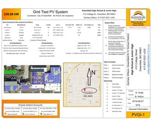
  • 1. Empire District Accounts The Kitchen Meter: 99.84kW The Notch Meter: 99.84kW The Junior High Meter: 31.2kW Account #310966-34-026 Account #310966-34-713 Account #310966-34-698 Meter #91060229 Meter #70060004 Meter #00201119 Jurisdiction: City of Greenfield No Permit, No Inspection Greenfield High School & Junior High 410 College St., Greenfied, MO 65661 Zachary Wilson: 417-637-5321 x335 230.88 kW ZacharyWilson,GreenfieldR-1VSchoolDistrict HighSchool&JuniorHigh 410CollegeStreet Greenfield,MO65661 417-637-5321x335 zwilson@greenfield.k12.mo.us Missouri Sun Solar, LLC 260 Old State Rd. Ellisville, MO 63021 PVGI-1 Designer D. Hults Reviewer B. Arthur General Information Grid Tied PV System Date 2016-06-27 Scale NTS System Specifications, Main Components: Roof Mount Item Manufacturer Model Quantity Size: In Array Area: Sqft Weight: Lbs Array Weight: Lbs Watts Panel Module Q-Cell Q-Pro.G4 260 888 65.7 x 39.4 x 1.38 17,212 41.89 37869 260 Inverter 1 Fronius Primo 10.0-1 1 20.1 x 28.5 x 8.9 82.5 1000 Inverter 2 Fronius Primo 8.2-1 2 16.9 x 24.7 x 8.1 47.29 8200 Inverter 3 Huwaei SUN2000-30KTL-US 6 21.7×30.3×10.6 121 30000 Attachment S-5! S-5-U Clamp MINI Ballasted Racking Dynoraxx Evolution FR Roof System Roof Specifications Site Specifications Array Specifications Steel Truss or Metal/Wood Framing to Code. Occupancy: Educational Design Low Temp: '-20° F Flat Roof, Gravel Topped with Ballasted Racking Building Size: 1 & 2 Story Areas Design High Temp: 110° F Metal Roof Standing Seam with Fixed Racking Design Wind Speed: 90 MPH Azimuths: 180° Flat Membrane Roof - NO USE Exposure Category: B Tilt Angle: 10° in Ballasted Array, flush Mount with Roof on Metal Roof Ground Snow Load: 20 PSF Table of Contents PVGI-1 General Information PVAL-2 Array Layout PVSL-3 String Layout PVMN-4 Materials & Notes PVED-5 Electrical Diagram Attachments 1) Panel Data 2) Panel Warranty 3) Inverter 1 & 2 Data 4) Inverter 1 & 2 Warranty 5) Inverter 3 Data 6) Inverter 3 Warranty 7) Transformer Data 8) AC Disconnect 1 P 9) AC Disconnect 3P 10) Attachment Data Scope of Work 1) Scope includes the installation of a Photovoltaic Array in a Roof Mounted Racking System including related Hardware and Electrical Equipment 2) All Electricity generated is for consumption on the site 3) Permit shall include labor of running of Electrical Conduit(s), installation of new Electrical Equipment, and Electrical Connection to the Existing Site Building 4) The Project does not include the installation of Batteries 1 1 2 3 2 3 Revision 6-27-16; DH: As-Built 2
  • 2. M D Missouri Sun Solar, LLC 260 Old State Rd. Ellisville, MO 63021 PVAL-2 Designer D. Hults Reviewer B. Arthur Array Layouts ZacharyWilson,GreenfieldR-1VSchoolDistrict HighSchool&JuniorHigh 410CollegeStreet Greenfield,MO65661 417-637-5321x335 zwilson@greenfield.k12.mo.us Date 2016-06-27 Scale NTS N M D M D "The Notch": Exterior East Wall of Building Existing Meter: #70060004 3-Phase Service, 120/208 V Existing Service Panels: 400A, 600A, 800A Solar AC Disconnect Solar Transformer: 480V - 240V Solar Subpanel Solar Inverters: Huwaei SUN2000-30KTL (x3) Solar Panel Load: 388 Panels: 99.84 kW Location of Arrays: Sloped Metal Rooftop Directly East of Meter Solar Panel Module: Q-Cell Q-Pro.G4 260 "The Kitchen": Exterior North Wall of Building Existing Meter: #91060229 3-Phase Service, 120/208 V Existing Service Panel: 400A Solar AC Disconnect Solar Transformer: 480V - 208V Solar Subpanel Solar Inverters: Huwaei SUN2000-30KTL (x3) Solar Panel Load: 388 Panels: 99.84 kW Location of Arrays: Flat Gravel Rooftops Directly South of Meter Solar Panel Module: Q-Cell Q-Pro.G4 260 "The Junior High": Exterior South Wall of Building Existing Meter: #00201119 1-Phase Service, 240V Existing Service Panel: 400A Solar AC Disconnect Solar Subpanel Solar Inverters: Fronius Primo 8.2-1 (2x) and 6.0-1 (x2) Solar Panel Load: 120 Panels: 31.2kW Location of Arrays: Sloped Metal Roof Directly Above Meter Solar Panel Module: Q-Cell Q-Pro.G4 260 School Entrances DO NOT TOUCH MEMBRANE ROOF DO NOT TOUCH MEMBRANE ROOF Revision 6-27-16; DH: As-Built 2
  • 3. M D M D Missouri Sun Solar, LLC 260 Old State Rd. Ellisville, MO 63021 PVAL-2 Designer D. Hults Reviewer B. Arthur Array Layouts ZacharyWilson,GreenfieldR-1VSchoolDistrict HighSchool&JuniorHigh 410CollegeStreet Greenfield,MO65661 417-637-5321x335 zwilson@greenfield.k12.mo.us Date 2016-06-27 Scale NTS N DO NOT TOUCH MEMBRANE ROOF M D Junior High School Arrays: 120 Panels: 31.2kW Inverters: Fronius Primo 10.0-1 4 Strings of 12 (2x) Fronius Primo 8.2-1 3 Strings of 12 The Kitchen: 388 Panels: 99.84kW Inverters: (3x) Huwaei SUN2000-30KTL The Notch: 388 Panels: 99.84kW Inverters: (3x) Huwaei SUN2000-30KTL INVS INVS INVS # Panels: String Color 23: 22: 21: 20: 19: 18: High School Arrays: 776 Panels: 199.68kW 1 2 12 11 10 98 7 6 5 4 3 3 2 1 12 11 98 10 7 6 4 5 15 16 17 18 14 13 13 15 16 17 18 14 15 1617 18 14 5 4 3 1 2 10 9 8 6 7 13 12 11 15 16 1718 14 5 4 3 1 2 10 9 8 6 7 13 1211 19 19 1 1 2 3 4 5 6 7 9 10 8 2 3 4 5 6 7 9 10 8 Revision 6-27-16; DH: As-Built 2
  • 4. PVSA-4 Missouri Sun Solar, LLC 260 Old State Rd. Ellisville, MO 63021 Designer D. Hults Reviewer B. Arthur String Assignment ZacharyWilson,GreenfieldR-1VSchoolDistrict HighSchool&JuniorHigh 410CollegeStreet Greenfield,MO65661 417-637-5321x335 zwilson@greenfield.k12.mo.us Date 2016-06-21 Scale NTS Junior High: 120 Panels: 31.2kW Fronius #2 Primo 8.2-1 Fronius#2 Primo 8.2 -1 Fronius #1 Primo 10.0-1 1. 12 4. 12 7. 12 9. 12 2. 12 5. 12 8. 12 10. 12 3. 12 6. 12 36 Panels 36 Panels 48 Panels The Kitchen: 388 Panels: 99.84kW Huwaeii 30kW #3.1 Huwaeii 30kW #3.2 Huwaeii 30kW #3.3 1. 22 7. 22 14. 19 2. 22 8. 20 15. 21 3. 19 9. 20 16. 21 4. 22 10. 20 17. 21 5. 22 11. 20 18. 21 6. 22 12. 19 19. 21 13. 18 129 Panels 139 Panels 124 Panels The Notch: 388 Panels: 99.84kW Huwaeii 30kW #3.1 Huwaeii 30kW #3.2 Huwaeii 30kW #3.3 1. 20 7. 23 13. 21 2. 19 8. 23 14. 21 3. 18 9. 23 15. 21 4. 23 10. 23 16. 21 5. 23 11. 19 17. 19 6. 23 12. 23 18. 21 126 Panels 134 Panels 124 Panels Revision 6-27-16; DH: As-Built 2
  • 5. DC AC 3DC AC 3DC AC DC AC DC AC 3DC AC 3DC AC WireSchedule TagWireTypeGroundConduitLength A#10AWGTHHNCu#10THHN1-1/4"EMT200' B#8AWGTHHNCu#6THHN3/4"EMT20' C#6AWGTHHNCu#6THHN3/4"EMT20' D#2AWGTHHNCu#1THHN1-1/2"Sealtight20' E250KCMICu#3THHN2-1/2"Sealtight20' PVED-5 Missouri Sun Solar, LLC 260 Old State Rd. Ellisville, MO 63021 Designer D. Hults Reviewer B. Arthur Electrical Diagram ZacharyWilson,GreenfieldR-1VSchoolDistrict HighSchool&JuniorHigh 410CollegeStreet Greenfield,MO65661 417-637-5321x335 zwilson@greenfield.k12.mo.us Date 2016-06-27 Scale NTS All Equipment Clearly Labeled with Descriptive Signage Roof Existing Electrical Panel Loads 888 Q-Cell 260W Solar Panels Module Q.Pro-G4 260 Inverters: #1 Fronius Primo 10.0-1 (x1) #2 Fronius Primo 8.2-1 (x2) #3 Huwaei 2000-30TKL-US (x6) M To Utility Rex Custom Transformer 480-240Delta, 125kva A 48 Panels 36 Panels 36 Panels Exterior Wall of Buildings or Electrical Poles Adjacent to the Buildings 126 Panels 134 Panels 124 Panels 124 Panels 129 Panels 139 Panels TheKitchen:99.84kWTheNotch:99.84kWJr.HighSchool:31.2kW 70A Subpanel 225A / 240V Fused AC Disconnect Square -D D325NRB 400A / 240V 175A Type R Fuses 50A 50A Fused AC Disconnect Square -D H365NR 400A / 600V Fused AC Disconnect Square -D H365NR 400A / 600V To Utility To Utility C B A C B A C B A 50A 70A 50A M M Strings 13 - 18 Strings 7 - 12 Strings 1 - 6 Strings 13 - 18 Strings 7 - 12 Strings 1 - 6 Strings 7 - 10 Strings 1 - 3 Strings 4 - 6 Linetap: Burndy 250-10 One Sided Unitap In Existing Enclosure Existing Electrical Panel Loads Existing Electrical Loads C B A C B A C B A 50A 70A 50A Subpanel 400A / 600V Subpanel 400A / 600V REX Custom Transformer 480V - 208V, 125kva Jr. High Meter #00201119 Existing Meter Combo Box 1P, 400A / 240V HS Notch Meter #70060004 3P, 400A / 208Delta HS Kitchen Meter #91060229 3P, 600A / 208V A A A A A A A A B B B C B B C D D E E E E DD INV3.2 INV3.2 * * INV3.3 INV3.1 INV3.3 INV3.1 Revision 6-27-16; DH: As-Built 2 * * Existing Wire Existing Disconnect 800A / 600VPOI on Open Lug of Disconnect Existing Wire Existing Wire Existing MDP 600A / 600V 350A TP 350A Type R Fuses 350A Type R Fuses
  • 6. Q.PRO BFR-G4 255-265 1 APT test conditions: Cells at -1000 V against grounded, with conductive me- tal foil covered module surface, 25 °C, 168 h 2 See data sheet on rear for further information. POLYCRYSTALLINE SOLAR MODULE The new Q.PRO BFR-G4 is the result of the continued evolution of our Q.PRO family. Thanks to improved power yield, excellent reliability, and high-level operational safety, the new Q.PRO BFR-G4 generates electricity at a low cost (LCOE) and is suitable for a wide range of applications. THE IDEAL SOLUTION FOR: Rooftop arrays on commercial / industrial buildings Ground-mounted solar power plants Rooftop arrays on residential buildings LOW ELECTRICITY GENERATION COSTS Higher yield per surface area and lower BOS costs thanks to higher power classes and an efficiency rate of up to 16.2 %. INNOVATIVE ALL-WEATHER TECHNOLOGY Optimal yields, whatever the weather with excellent low-light and temperature behavior. ENDURING HIGH PERFORMANCE Long-term yield security with Anti-PID Technology1 , Hot-Spot-Protect and Traceable Quality Tra.Q™. LIGHT-WEIGHT QUALITY FRAME High-tech aluminum alloy frame, certified for high snow (5400 Pa) and wind loads (4000 Pa). MAXIMUM COST REDUCTIONS Up to 10 % lower logistics costs due to higher module capacity per box. SAFE ELECTRONICS Protection against short circuits and thermally induced power losses due to breathable junction box and welded cables. A RELIABLE INVESTMENT Inclusive 12-year product warranty and 25-year linear performance guarantee2 . ANTI PID TECHNOLOGY (APT) HOT-SPOT PROTECT (HSP) TRACEABLE QUALITY (TRA.Q™) YIELD SECURITY 151 modules tested Best polycrystalline solar module 2013 Q.PRO-G2 235 MOD:27898 photon.info/laboratory    Quality Tested ID. 40032587 high reliability low degradation frequent product surveillance Missouri Sun Solar: Greenfield High School & Jr. High, 230.88kW 1) Panel Data
  • 7. MECHANICAL SPECIFICATION Format 65.7 in × 39.4 in x 1.26 in (including frame) (1670 mm × 1000 mm × 32 mm) Weight 41.45 lb (18.8 kg) Front Cover 0.13 in (3.2 mm) thermally pre-stressed glass with anti-reflection technology Back Cover Composite film Frame Black anodized aluminum Cell 6 × 10 polycrystalline solar cells Junction box 4.33 in × 4.53 in × 0.9 in (110 mm × 115 mm × 23 mm), Protection class IP67, with bypass diodes Cable 4 mm² Solar cable; (+) ≥ 39.37 in (1000 mm), (-) ≥ 39.37 in (1000 mm) Connector Tyco Solarlok PV4, IP68 NA DETAIL A 0.630" (16 mm) 0.335" (8.5 mm) 0.965" (24.5 mm) Junction bo× Product label 38.58" (980 mm) 65.7" (1670 mm) 4 × Fastening points (DETAIL A) Cable with connectors Frame 5.90" (150 mm) 39.4" (1000 mm) 37.44" (951 mm) 1.26" (32 mm) 8 × Drainage holes 6 × Grounding points ø 0.177" (4.5 mm) 39.37" (1000 mm) Q CELLS PERFORMANCE WARRANTY PERFORMANCE AT LOW IRRADIANCE IRRADIANCE [W/m²] RELATIVEEFFICIENCY[%] 100 200 300 400 500 600 700 800 900 1000 105 100 95 90 85 80 Irradiance [W/m²] Relativeefficiency[%] PROPERTIES FOR SYSTEM DESIGN Maximum System Voltage VSYS [V] 1000 (IEC) / 1000 (UL) Safety Class II Maximum Series Fuse Rating [A DC] 20 Fire Rating C / TYPE 1 Max Load (UL)2 [lbs/ft2 ] 75 (3600 Pa) Permitted module temperature on continuous duty − 40 °F up to +185 °F (− 40 °C up to +85 °C) Load Rating (UL)2 [lbs/ft2 ] 55.6 (2666 Pa) 2 see installation manual QUALIFICATIONS AND CERTIFICATES PACKAGING INFORMATION Number of Modules per Pallet 32 Number of Pallets per 53' Container 32 Number of Pallets per 40' Container 26 Pallet Dimensions ( L × W × H ) 68.7 in × 45.0 in × 46.0 in (1745 × 1145 × 1170 mm) Pallet Weight 1323 lb (651 kg) NOTE: Installation instructions must be followed. See the installation and operating manual or contact our technical service department for further information on approved installation and use of this product. EN RELATIVEEFFICIENCY COMPAREDTONOMINALPOWER[%] 100 95 90 85 80 75 155 25200 10 YEARS 97 Q CELLS Industry standard for tiered warranties* Industry standard for linear warranties* * Standard terms of guarantee for the 10 PV companies with the highest production capacity in 2014 (as at: September 2014) Certified UL 1703 (254141) TEMPERATURE COEFFICIENTS Temperature Coefficient of ISC α [% / K] + 0.04 Temperature Coefficient of VOC β [% / K] − 0.30 Temperature Coefficient of PMPP γ [% / K] − 0.41 Normal Operating Cell Temperature NOCT [°F] 113 ± 5.4 (45 ± 3 °C) UL 1703; VDE Quality Tested; CE-compliant; IEC 61215 (Ed.2); IEC 61730 (Ed.1) application class A Specificationssubjecttotechnicalchanges©HanwhaQ CELLSGmbHQ.PROBFR-G4_2015-04_Rev03_NA At least 97 % of nominal power during first year. Thereafter max. 0.6 % degra- dation per year. At least 92 % of nominal power after 10 years. At least 83 % of nominal power after 25 years. All data within measurement tolerances. Full warranties in accordance with the warranty terms of the Q CELLS sales organisation of your respective country. The typical change in module efficiency at an irradiance of 200 W/m² in relation to 1000 W/m² (both at 25 °C and AM 1.5 G spectrum) is -2 % (relative). Hanwha Q CELLS USA Corp. 300 Spectrum Center Drive, Suite 1250, Irvine, CA 92618, USA | TEL +1 949 748 59 96 | EMAIL q-cells-usa@q-cells.com | WEB www.q-cells.us ELECTRICAL CHARACTERISTICS POWER CLASS 255 260 265 MINIMUM PERFORMANCE AT STANDARD TEST CONDITIONS, STC1 (POWER TOLERANCE +5 W /- 0 W) Minimum Power at MPP2 PMPP [W] 255 260 265 Short Circuit Current* ISC [A] 9.07 9.15 9.23 Open Circuit Voltage* VOC [V] 37.54 37.77 38.01 Current at MPP* IMPP [A] 8.45 8.53 8.62 Voltage at MPP* VMPP [V] 30.18 30.46 30.75 Efficiency2 η [%] ≥ 15.3 ≥ 15.6 ≥ 15.9 MINIMUM PERFORMANCE AT NORMAL OPERATING CONDITIONS, NOC3 Minimum Power at MPP2 PMPP [W] 188.3 192.0 195.7 Short Circuit Current* ISC [A] 7.31 7.38 7.44 Open Circuit Voltage* VOC [V] 34.95 35.16 35.38 Current at MPP* IMPP [A] 6.61 6.68 6.75 Voltage at MPP* VMPP [V] 28.48 28.75 29.01 1 1000 W/m², 25 °C, spectrum AM 1.5 G 2 Measurement tolerances STC ± 3 %; NOC ± 5 % 3 800 W/m², NOCT, spectrum AM 1.5 G * typical values, actual values may differ Missouri Sun Solar: Greenfield High School & Jr. High, 230.88kW
  • 8. SCOPE The following warranty terms and conditions apply exclusively to Q CELLS photovoltaic modules of the following types: • Q.PRO-G4, Q.PRO BFR-G4, Q.PRO BLK-G4, Q.PRO-G4/SC, Q.PLUS-G4 • Q.PEAK-G3, Q.PEAK BLK-G3 • Q.PRO-G3, Q.PRO BFR-G3, Q.PLUS-G3 • Q.PRO L, Q.PRO L-G2, Q.PRO L-G3, Q.PRO L-G3.1, Q.PRO L-G4, Q.PLUS L-G4 manufactured by Q CELLS, sold and installed within the United States, Canada, Mexico, Panama and Costa Rica and which bear the manufac- turer’s label of Q CELLS. Warrantor is the Hanwha Q CELLS GmbH, OT Thalheim, Sonnenallee 17- 21, 06766 Bitterfeld-Wolfen, Germany. The warranty period begins with the initial purchase of the solar modules by the end customer; the date of invoice is relevant. Any performances of services under this limited warranty will not extend the warranty period. 12-YEAR PRODUCT WARRANTY Q CELLS warrants that modules under normal operating conditions and which are installed, used and serviced in accordance with the relevant prod- uct information, particularly the installation instructions, will not show any material defects or workmanship defects for a period of 12 (twelve) years af- ter initial purchase. In the event that a module has a defect covered by this warranty (case of warranty), Q CELLS undertakes to remedy the situation within a reasonable time and may choose, at its sole discretion, whether to repair the defect or to supply a module which is free of defects. In no event shall Q CELLS be liable for any indirect, consequential or extra-contractual damages. 25-YEAR LINEAR PERFORMANCE WARRANTY2 In addition, Q CELLS provides the following performance warranty for modules which are installed in accordance with the relevant module specifications and other product documentations. In the first year after the initial purchase the crystalline modules will pro- duce a minimum power output of at least 97 % specified in the module data sheet. From the 2nd year onwards and for a duration of 24 years the crystalline modules will have a yearly maximum decrease (degradation) of power of not more than 0.6 %, i.e. after 25 years the crystalline module will have a minimum power output of at least 83 % of the minimum power output specified in the module data sheet. All power data refers to measurements under the STC Standard Test Con- ditions applicable at the beginning of this warranty. The STC Standard Test Conditions are customary standardized basic conditions for the mea- surement of the power of solar modules. The currently valid Standard Test Conditions are defined in the IEC standards EN 61215 and 60904-3. In the event of a claim being made under the warranty Q CELLS shall be free to decide at its own discretion to make up the difference to the guaranteed power output by refinishing the system by replacing the mod- ule or by supplying additional modules as described in “warranty claims and entitlements” or by repaying the purchase price of the modules or by reducing the purchase price in proportion of the actual power to the guaranteed power, taking into account an annual depreciation rate on the original purchase price as evidenced by the invoice produced by the customer. Other payments of whatever nature, including, but not limited to the compensation for expenses or for related damages, shall not be covered by the warranty. WARRANTY TERMS AND CONDITIONS FOR CRYSTALLINE PHOTOVOLTAIC MODULES FROM HANWHA Q CELLS GMBH Valid from March 1st, 2015 SUMMARY OF LIMITED WARRANTY TERMS AND CONDITIONS 12 YEARS PRODUCT WARRANTY For material defects or processing defects. HOT-SPOT PROTECT and ANTI PID TECHNOLOGY1 . 25 YEARS LINEAR PERFORMANCE WARRANTY At least 97 % of the nominal power within the first year. Thereafter, decrease of the power output will not exceed 0.6 % p. a. Minimal nominal rated power after 25 years at least 83 %. Dear Customer, You have made an excellent choice in purchasing quality Q CELLS modules manufactured by the Hanwha Q CELLS GmbH (thereafter, Q CELLS), OT Thalheim, Sonnenallee 17-21, 06766 Bitterfeld-Wolfen, Germany. The photovoltaic modules you have purchased have been manufactured with great care and have undergone a final functional test. If, however, a module shows a material defect or a processing defect or suffers a loss of power during the warranty period, we provide the following Q CELLS limited warranty, subject to the terms and conditions hereof. 1 HOT-SPOT PROTECT: The modules are safe against backside destruction caused by Hot-Spot effects due to partial shading of modules. ANTI PID TECHNOLOGY: The modules are safe against potential-induced degradation in accordance to the test criteria: Cells at -1000 V against grounded, with conductive metal foil covered module surface, 25 °C, 168 h 2 All data referering to the module power / performance are within the framework of the power tolerances as defined in the respective data sheet. Missouri Sun Solar: Greenfield High School & Jr. High, 230.88kW 2) Panel Warranty
  • 9. EXCLUSIONS FROM THE LIMITED PRODUCT AND PERFORMANCE WARRANTIES Irrespective of contributory root causes, this limited warranty does not cover the following cases: • incorrect usage, misuse, modifications of the modules or incorrect han- dling including usage or handling in any manner that is contrary to the instructions provided in this regard by Q CELLS for the customer un- der any module specifications and/or product documentation for such product; • errors relating to the transport, storage, installation, or use, e.g. through non-compliance with installation and operating manual or any other in- structions issued by Q CELLS for the customer in this regard at the time of purchase, incorrect static, etc.; • incorrect system configuration, e.g. installation of mutually incompat- ible modules, as well as inadequate system design, particularly (but not limited to) incompatible inverter; • incorrect or inadequate servicing or maintenance work (cf. information set out in the relevant product information); • usage for unusual purposes or purposes specifically categorized as be- ing unsuitable for usage of the product, in unusual circumstances or in unsuitable ambient conditions not conforming to the product specifica- tions (as set out in the module data sheet applicable to the modules in any given case) or not complying with the installation and operating instructions; • damage caused by extreme environmental sources of impact, including, but not limited to such as acid rain, saline air, pollution of any kind as well as fire, explosion, smoke or charring; • damage caused by acts of nature or acts of god, including, but not limited to lightning, hail, frost, snow, storms, tidal waves, floods, earth- quakes, typhoons, volcanic eruptions, ground motions, earth fissures or landslides; • damage caused directly or indirectly by acts of violence or intervention by third parties or external forces, such as misadventure, riots, war, in- surrection, communal violence or vandalism as well as damage caused by game animals and other forces majeures; • damage to the photovoltaic system in which the modules are installed, most notably caused by factors, including, but not limited to such as voltage fluctuations, power peaks, excess current, power failure poor electrical or mechanical engineering work, or other faults occurring in a power supply system with or without mains connection, whether or not such faults in the power supply system was contributed to by any act or omission of the customer; The following cases are also excluded from the warranty: • the Q CELLS modules are modified or used in processes involving other products without obtaining written consent from Q CELLS; • scratches, marks, mechanical wear, rust, mold, degradation, discolor- ation and other changes which occur after the delivery of the modules by Q CELLS but which do not result in any adverse effect on the me- chanical stability of the product or a reduction of performance which exceeds the levels set out in the performance warranty; • Inadequate system size, in particular the incorrect selection of the AC power inverter; • The serial number or product label has been removed, changed, deleted or made unrecognizable or it is no longer clearly distinguishable and leg- ible for other reasons beyond Q CELLS’ reasonable control and therefore it is not possible to conclusively identify the modules. This limited warranty does not apply to modules which are used on mobile carriers such as motor vehicles or ships. The same applies to the usage of modules in high snow loads where the conditions of use exceed the specifications set out in the relevant product information. As part of the limited warranty there is no right to compensation for or the reimbursement of costs for dismantling, installation or replacement, loss of yield or other indirect damages. In no event shall Q CELLS be liable for any indirect, consequential or extra-contractual damages. CLAIMS UNDER THE LIMITED PRODUCT AND PERFORMANCE WARRANTY / NOTIFICATION OF DEFECTS The supplied modules must be checked for visible defects when they are purchased. Any defects discovered during this process must be reported immediately to the vendor, if any, who shall be the first point of contact for the end customer or photovoltaic system owner. In case there is no other vendor, the first point of contact shall be Hanwha Q CELLS USA Corp. (with contact details as referred to below), who then shall immedi- ately inform Q CELLS accordingly. If the defects are not reported immediately to the vendor or Hanwha Q CELLS USA, the warranty becomes discharged. Any warranty claim must be reported to the vendor or Hanwha Q CELLS USA Corp. prior to the end of the applicable warranty period and no later than 30 days after discover- ing the breach of warranty. Please contact the vendor or Hanwha Q CELLS USA Corp. first in writing or electronically. Contact information, the required data and the proce- dure of the complaint process are described in the RMA process docu- ment (Return Merchandise Authorization) available at Hanwha Q CELLS USA Corp.. If you have any questions please contact your seller or, as the case may be, Hanwha Q CELLS USA Corp. at the contact details referred to below or Q CELLS at the following e-mail address: service@q-cells.com. We ask for our customers’ understanding that Q CELLS cannot accept any unauthorized return shipments of modules and the company will not take delivery of such items. PERFORMANCE OF THE WARRANTY SERVICES • In all cases, Q CELLS shall have the choice, at its sole and absolute discretion, as to how warranty claims are settled. Q CELLS may use the services of a customer service unit or a service partner for this purpose as deemed fit by Q CELLS. Additional agreements may be made in con- tract form in a service level agreement with Q CELLS. • Q CELLS shall pay the costs of a technical inspection and transport in the event that the warranty claim is confirmed by such inspection. Otherwise the claimant shall be charged with these costs. • Q CELLS shall only be liable under the limited performance warranty if and only in the situation wherein the performance (i.e. module power) measured by Q CELLS under the STCs (Standard Test Conditions) does not meet the performance. • The Customer must comply with the Return Merchandise Authorization (RMA) issued by Q CELLS. Missouri Sun Solar: Greenfield High School & Jr. High, 230.88kW
  • 10. Subjecttomodifications.©HanwhaQ CELLSWarranty_terms_modules_US_2015-03_Rev17_NA Hanwha Q CELLS USA Corp. 300 Spectrum Center Drive, Suite 1250, Irvine, CA 92618, USA | TEL +1 949 748 59 96 | EMAIL q-cells-usa@q-cells.com | WEB www.q-cells.us • The Customer must submit the original receipt or invoice which bears the date of purchase, the serial numbers of the relevant modules, and the name of the authorized seller. • The modules sent to Q CELLS in the course of the RMA process shall remain the property of the customer until any inspection has been com- pleted and Q CELLS provides a replacement or refund. If under the warranty a replacement or refund takes place, the ownership of these modules passes to Q CELLS. • Any repaired, replacement or additionally supplied module hereunder will be warranted only for the remainder of the original warranty period applicable to the original module. • Q CELLS hereby assures that any replacement parts used for the recti- fication of defects shall be of equivalent or better quality, and that they shall be covered by the product warranty for the remaining portion of the original warranty period. • If Q CELLS supplies replacement or additional modules on the basis of these warranty terms and conditions the replacement or additional modules may be of a similar or equivalent type from the product range available at the time of the claim as long as they are suitable for the intended purpose and if the original module type is no longer available. • In the event of glass breakage a static calculation to verify the sub- structure is an additional prerequisite for exercising a claim under the limited warranty. • If a module is sold as a consumer product, to the extent required by applicable law, if Q CELLS cannot remedy the defective module after reasonable attempts, Q CELLS may elect to receive a replacement mod- ule or (i) with respect to the limited product warranty, a refund of the purchase price after taking into account an annual 4 % depreciation rate or (ii) with respect to the limited performance warranty, the lesser of the amount of such refund or a reduction of the purchase price in the same proportion as the power shortfall bears to the guaranteed power. WARRANTY LIMITATIONS THE EXCLUSIVE WARRANTY REMEDIES SET FORTH HEREIN ARE THE SOLE REMEDIES FOR ANY BREACH OF WARRANTY BY Q CELLS. THE EXPRESS WARRANTIES SET FORTH HEREIN ARE IN LIEU OF ALL OTHER WARRANTIES, WHETHER EXPRESS, IMPLIED, OR STATU- TORY, REGARDING ANY MODULES SUPPLIED BY Q CELLS, INCLUD- ING ANY IMPLIED WARRANTIES OF MERCHANTABILITY, FITNESS FOR A PARTICULAR PURPOSE OR NON-INFRINGEMENT; PROVIDED, THAT IF A MODULE IS SOLD AS A CONSUMER PRODUCT, TO THE EXTENT REQUIRED BY APPLICABLE LAW, ANY IMPLIED WARRANTIES OF MERCHANTABILITY, FITNESS FOR A PARTICULAR PURPOSE OR NON-INFRINGEMENT ARE LIMITED TO THE PERIODS OF THE LIMIT- ED PRODUCT AND LIMITED PERFORMANCE WARRANTIES SET FORTH ABOVE, OR SUCH SHORTER PERIOD(S) AS REQUIRED BY APPLICA- BLE LAW. THIS LIMITED WARRANTY GIVES CUSTOMERS SPECIFIC LEGAL RIGHTS, AND CUSTOMER MAY ALSO HAVE OTHER RIGHTS WHICH VARY FROM STATE TO STATE. Q CELLS IS NOT RESPONSIBLE OR LIABLE IN ANY WAY FOR DAMAGE OR INJURY TO PERSONS OR PROPERTY, OR FOR OTHER LOSS OR INJURY RESULTING FROM ANY CAUSE WHATSOEVER, ARISING OUT OF OR RELATED TO ANY MOD- ULES SUPPLIED BY Q CELLS. IN NO EVENT WILL Q CELLS BE LIABLE FOR ANY LOSS OF REVENUE, OR CONSEQUENTIAL, INDIRECT, EXEMPLARY, SPECIAL OR INCIDEN- TAL DAMAGES, ARISING FROM OR RELATING TO THIS WARRANTY OR ANY MODULE OR ANY REPLACEMENT OR ADDITIONAL MODULE SUP- PLIED BY Q CELLS HEREUNDER EVEN IF AWARE OF THE POSSIBILITY OF SUCH DAMAGES. Q CELLS’ TOTAL LIABILITY ARISING FROM OR RELATING TO THIS WARRANTY, WHETHER IN CONTRACT OR TORT OR OTHERWISE, WILL NOT EX CEED THE AMOUNT PAID TO Q CELLS OR ITS SUBSIDIARIES FOR THE MODULE WHICH IS THE SUBJECT OF THE CLAIM(S) OR DISPUTE(S). SOME STATES DO NOT ALLOW THE EXCLUSION OR LIMITATION OF INCIDENTAL OR CONSEQUENTIAL DAMAGES, SO THE ABOVE LIMITATION OR EXCLUSION MAY NOT AP- PLY TO CUSTOMER. TRANSFER OF LIMITED WARRANTY This limited warranty is transferable with respect to any module to a new owner of the entire photovoltaic system in which such module is originally installed, provided that such system remains intact in its original place of installation. This warranty may not otherwise be assigned or transferred. GENERAL If any provision of these limited warranty terms and conditions is held to be invalid, illegal or unenforceable in any respect, such provision will be changed and interpreted to accomplish the objectives of such provision to the greatest extent possible under applicable law and the remaining provisions will continue in full force and effect. These warranty terms and conditions shall be exclusively governed by German law. The UN Convention on Contracts for the International Sale of Goods shall not apply. All statutory warranty rights which you have in case of a material defect or a legal defect against your seller in accordance with the applicable sales law are not restricted by this warranty. You can exercise your statutory warranty rights against the seller regardless of whether there is a warranty case or whether you exercise a claim to us under this warranty. Missouri Sun Solar: Greenfield High School & Jr. High, 230.88kW
  • 11. / Perfect Welding / Solar Energy / Perfect Charging / With power categories ranging from 3.8 kW to 15.0 kW, the transformerless Fronius Primo is the ideal compact single-phase inverter for residential applications. The sleek design is equipped with the SnapINverter hinge mounting system which allows for lightweight, secure and convenient installation and service. The Fronius Primo has several integrated features that set it apart from competitors including dual powerpoint trackers, high system voltage, a wide input voltage range, Wi-Fi* and SunSpec Modbus interface for seamless monitoring and datalogging, Arc Fault Circuit Interruption (AFCI), and Fronius’ online and mobile platform Fronius Solar.web. The Fronius Primo is designed to adjust to future standards, offering a complete solution to code restrictions and technical innovations of tomorrow. It also works seamlessly with the Fronius Rapid Shutdown Box for a reliable NEC 2014 solution. TECHNICAL DATA FRONIUS PRIMO / The future of residential solar is here - Introducing the new Fronius Primo. / SuperFlex Design / Wi-Fi®* interface / Smart Grid Ready / Arc Fault Circuit Interruption / SnapINverter mounting system / PC board replacement process FRONIUS PRIMO GENERAL DATA FRONIUS PRIMO 3.8 - 8.2 FRONIUS PRIMO 10.0-15.0 Dimensions (width x height x depth) 16.9 x 24.7 x 8.1 in. 20.1 x 28.5 x 8.9 in. Weight 47.29 lb. 82.5 lbs. Degree of protection NEMA 4X Night time consumption < 1 W Inverter topology Transformerless Cooling Variable speed fan Installation Indoor and outdoor installation Ambient operating temperature range -40 - 131°F (-40 - 55°C) -40 - 140°F (-40 - 60°C) Permitted humidity 0 - 100 % DC connection terminals 4x DC+ and 4x DC- screw terminals for copper (solid / stranded / fine stranded) or aluminum (solid / stranded) 4x DC+1, 2x DC+2 and 6x DC- screw terminals for copper (solid / stranded / fine stranded) or aluminum (solid / stranded) AC connection terminals Screw terminals 12 - 6 AWG Revenue Grade Metering Optional (ANSI C12.1 accuracy) Certificates and compliance with standards UL 1741-2010, UL1998 (for functions: AFCI and isolation monitoring), IEEE 1547-2003, IEEE 1547.1-2003, ANSI/IEEE C62.41, FCC Part 15 A & B, NEC Article 690, C22. 2 No. 107.1-01 (September 2001) , UL1699B Issue 2 -2013, CSA TIL M-07 Issue 1 -2013 UL 1741-2015, UL1998 (for functions: AFCI, RCMU and isolation monitoring), IEEE 1547-2003, IEEE 1547.1-2003, ANSI/IEEE C62.41, FCC Part 15 A & B, NEC Article 690-2014, C22. 2 No. 107.1-01 (September 2001) , UL1699B Issue 2 -2013, CSA TIL M-07 Issue 1 -2013 PROTECTIVE DEVICES STANDARD WITH ALL PRIMO MODELS AFCI & 2014 NEC Ready Yes Ground Fault Protection with Isolation Monitor Interrupter Yes DC disconnect Yes DC reverse polarity protection Yes N W S E INTERFACES STANDARD WITH ALL PRIMO MODELS Wi-Fi*/Ethernet/Serial Wireless standard 802.11 b/g/n / Fronius Solar.web, SunSpec Modbus TCP, JSON / SunSpec Modbus RTU 6 inputs or 4 digital inputs/outputs External relay controls USB (A socket) Datalogging and/or updating via USB 2x RS422 (RJ45 socket) Fronius Solar Net, interface protocol Datalogger and Webserver Included *The term Wi-Fi® is a registered trademark of the Wi-Fi Alliance. 3) Inverter #1 & 2 DataMissouri Sun Solar: Greenfield High School & Jr. High, 230.88kW
  • 12. Rev. 11.3.15 USA / Perfect Welding / Solar Energy / Perfect Charging v05 May 2015 EN Textandimagescorrespondtothecurrentstateoftechnologyatthetimeofprinting.Subjecttomodifications. Allinformationiswithoutguaranteeinspiteofcarefulediting-liabilityexcluded.Copyright©2011Fronius™.Allrightsreserved. Further information about all Fronius products and our global sales partners and representatives can be found at www.fronius.com WE HAVE THREE DIVISIONS AND ONE PASSION: SHIFTING THE LIMITS OF POSSIBILITY. / Whether welding technology, photovoltaics or battery charging technology − our goal is clearly defined: to be the innovation leader. With around 3,300 employees worldwide, we shift the limits of what’s possible - our record of over 900 granted patents is testimony to this. While others progress step by step, we innovate in leaps and bounds. Just as we’ve always done. The responsible use of our resources forms the basis of our corporate policy. Fronius USA LLC 6797 Fronius Drive Portage, IN 46368 USA pv-support-usa@fronius.com www.fronius-usa.com TECHNICAL DATA FRONIUS PRIMO INPUT DATA PRIMO 3.8-1 PRIMO 5.0-1 PRIMO 6.0-1 PRIMO 7.6-1 PRIMO 8.2-1 Recommended PV power (kWp) 3.0 - 6.0 kW 4.0 - 7.8 kW 4.8 - 9.3 kW 6.1 - 11.7 kW 6.6 - 12.7 kW Max. usable input current (MPPT 1/MPPT 2) 18 A / 18 A 18 A / 18 A 18 A / 18 A 18 A / 18 A 18 A / 18 A Total max. DC current 36 A Max. array short circuit current (1.25 Imax) (MPPT 1/ MPPT 2) 22.5 A / 22.5 A Operating voltage range 80 V - 600 V Max. input voltage 600 V Nominal input voltage 410 V 420 V 420 V 420 V 420 V Admissable conductor size DC AWG 14 - AWG 6 MPP Voltage Range 200 - 480 V 240 - 480 V 240 - 480 V 250 - 480 V 270 - 480 V Number of MPPT 2 OUTPUT DATA PRIMO 3.8-1 PRIMO 5.0-1 PRIMO 6.0-1 PRIMO 7.6-1 PRIMO 8.2-1 Max. output power 240 V 3800 W 5000 W 6000 W 7600 W 8200 W 208 V 3800 W 5000 W 6000 W 7600 W 7900 W Max. continuous output current 240 V 15.8 A 20.8 A 25.0 A 31.7 A 34.2 A 208 V 18.3 A 24.0 A 28.8 A 36.5 A 38.0 A Recommended OCPD/AC breaker size 240 V 20 A 30 A 35 A 40 A 45 A 208 V 25 A 30 A 40 A 50 A 50 A Max. Efficiency 96.7 % 96.9 % 96.9 % 96.9 % 97.0 % CEC Efficiency 240 V 95.0 % 95.5 % 96.0 % 96.0 % 96.5 % Admissable conductor size AC AWG 14 - AWG 6 Grid connection 208 / 240 V Frequency 60 Hz Total harmonic distortion < 5.0 % Power factor (cos φac,r) 0.85-1 ind./cap INPUT DATA PRIMO 10.0-1 PRIMO 11.4-1 PRIMO 12.5-1 PRIMO 15.0-1 Recommended PV power (kWp) 8.0 - 12.0 kW 9.1 - 13.7 kW 10.0 - 15.0 kW 12.0 - 18.0 kW Max. usable input current (MPPT 1/MPPT 2) 33.0 A / 18.0 A Total max. DC current 51 A Max. array short circuit current (1.25 Imax) (MPPT 1/MPPT 2) 41.3 A / 22.5 A Operating voltage range 80 V - 600 V Max. input voltage 600 V Nominal input voltage 415 V 420 V 425 V 440 V Admissable conductor size DC AWG 14 - AWG 6 copper direct, AWG 6 aluminum direct (AWG 10 copper or AWG 8 aluminium for overcurrent protective devices up to 60A, from 61 to 100A minimum AWG 8 for copper or AWG 6 aluminium has to be used), AWG 4 - AWG 2 copper or alu- minum with optional input combiner MPP Voltage Range 220 - 480 V 240 - 480 V 260 - 480 V 320 - 480 V Integrated DC string fuse holders 4- and 4+ for MPPT 1 / no fusing requried on MPPT 2 Number of MPPT 2 OUTPUT DATA PRIMO 10.0-1 PRIMO 11.4-1 PRIMO 12.5-1 PRIMO 15.0-1 Max. output power 240 V 9995 W 11400 W 12500 W 15000 W 208 V 9995 W 11400 W 12500 W 13750 W Max. continuous output current 240 V 41.6 A 47.5 A 52.1 A 62.5 A 208 V 48.1 A 54.8 A 60.1 A 66.1 A Recommended OCPD/AC breaker size 240 V 60 A 60 A 70 A 80 A 208 V 70 A 70 A 80 A 90 A Max. Efficiency 96.7 % CEC Efficiency 96.0 % 96.5 % Admissable conductor size AC AWG 10 - AWG 2 copper (solid / stranded / fine stranded)(AWG 10 copper or AWG 8 aluminium for overcurrent protective devices up to 60A, from 61 to 100A minimum AWG 8 for copper or AWG 6 aluminium has to be used) , AWG 6 - AWG 2 copper(solid / stranded) MultiContactWiringable with AWG 12 Grid connection 208 / 240 V Frequency 60 Hz Total harmonic distortion < 2.5 % Power factor (cos φac,r) 0-1 ind./cap. Missouri Sun Solar: Greenfield High School & Jr. High, 230.88kW
  • 13. SE_ToW_EN_US_0415 1/2 FRONIUS LIMITED WARRANTY TERMS AND CONDITIONS valid from: 10/15/2015 These limited warranty terms and conditions apply to original installation of Fronius inverters in the United States of America. The warranty agreement is concluded between Fronius and the warranty holder (owner of the installed system). Content of the warranty: Fronius Warranty Plus/Warranty Extension Plus The Fronius Warranty Plus/Warranty Extension Plus covers the costs of materials, servicing and transport under the terms and conditions indicated below. Fronius Warranty/Warranty Extension The Fronius Warranty/Warranty Extension covers the costs of materials under the terms and conditions indicated below. Duration of warranty: In each case the warranty period begins the day that the products leave the Fronius factory. Fronius string inverters (wall-mounted devices) Fronius string inverters are supplied with a 10-year Fronius Warranty Plus. Fronius central inverters (free-standing devices) Fronius central inverters are supplied with a 5-year Fronius Warranty Plus. Fronius Rapid Shut-down Box (RSB) Fronius Rapid Shut-down boxes are supplied with a 5-year Fronius Warranty Plus. Warranty services: If a fault should occur during the Fronius warranty period and the fault is covered by the limited warranty terms and conditions, Fronius reserves the right to  make the corresponding spare parts available,  make an equivalent replacement device available,  repair this fault at its premises or on the customer's premises,  or have these services carried out by a suitably-trained Fronius Service Partner. Materials "Materials" means that, during the warranty period, Fronius will bear the cost of materials (spare part or replacement device excluding labour costs) associated with the warranty service. Servicing The warranty covers the labour costs associated with the materials, provided that these are incurred by Fronius itself or a Fronius Service Partner (service fee). Other incidental costs (such as travel costs, installation costs, if these exceed the Fronius service fee, customs duties, etc.) are not covered by the warranties. Transport National transport costs are covered by the Fronius Warranty Plus and Fronius Warranty Extension Plus, provided that these are incurred in accordance with the standard claim procedures with the Fronius Service Provider. Fronius will not bear the costs of any unjustified or express deliveries. General provisions Devices or components are to be returned in the original or equivalent packaging. Fronius retains ownership of replacement devices and components inside or outside of the warranty/warranty exclusion until the faulty parts/devices have been received. In all cases ownership of the faulty device/parts is transferred to Fronius when the replacement device is received. If the faulty device/parts is/are not returned to Fronius within 60 days, they will be charged to the installer at the current replacement prices. Fronius Warranty Extension/Warranty Extension Plus An extended warranty can be purchased up to 30 months after dispatch by Fronius. Fronius may reject orders received later. The extended warranties only apply to Fronius inverters unambiguously identified by their serial number. It is possible to extend the warranty to 10, 15 or 20 years from dispatch by Fronius. Considerations when making a warranty claim First contact an installer, who will then contact Fronius if necessary. The Fronius warranty procedure must be strictly adhered to in the event of a warranty claim. This is the only way of ensuring that the warranty services remain free of charge for the warranty holder. The purchase invoice, serial number of the device and start- up report (the date on which the device was provided/commissioned and report from the power supply company), as well as proof of payment of the warranty extension fee, are required for warranty claims. The purchase price must have been paid to Fronius in full in order for the warranty service to be provided. When devices or components are replaced, the remaining warranty period is transferred to the replacement device or 4) Inverter #1 & 2 WarrantyMissouri Sun Solar: Greenfield High School & Jr. High, 230.88kW
  • 14. SE_ToW_EN_US_0415 2/2 replacement component. This is automatically registered at Fronius. A new certificate is not issued. If servicing is carried out on site, the client must guarantee unrestricted access to the Fronius inverters. If necessary, the warranty holder must make the equipment required by the applicable health and safety regulations available free of charge. Scope and validity of the warranty The Fronius warranties apply only to Fronius products that have been identified unambiguously by their serial number. These must be appropriately certified for the country of installation. The other components of the photovoltaic system as well as the system add-ons, system monitoring and data communication components, any accessories, and pre-production devices are excluded from the warranty. These components fall under the corresponding provisions of the applicable General Delivery and Payment Conditions of Fronius. Exclusions from the Fronius warranties Failure to observe the operating instructions, installation instructions or maintenance procedures.  Improper installation  Improper commissioning  Improper transportation  Improper or incorrect operation  Inadequate ventilation of the device  Any work performed on the device by companies or persons that have not been authorised by Fronius  Failure to observe safety rules and installation standards  Force majeure (storm, lightning, overvoltage, fire, etc.) Damage to the Fronius inverter caused by other components in the photovoltaic system or damage that does not impair the function of the Fronius inverter ("cosmetic flaws") is also excluded from the warranty. The warranty does not cover travel and accommodation expenses as well as on-site assembly and installation costs, if these exceed the service reimbursement paid to the installer by Fronius depending on the service and agreement. Changes to the existing PV system, in-house installation and similar or the time involved and the costs incurred are not covered by the warranty. Due to technological progress, the equivalent replacement or new device provided may not be compatible with the system monitoring or other components installed on site (e.g. Fronius DATCOM). The warranty does not cover the expenses and costs incurred as a result of upgrading system monitors or other components of the PV system. A claim for compensation cannot be made for energy that has not been fed into the grid or energy that has not been consumed in-house, etc. Fuses and other wearing parts are excluded from the warranty. Other legal information SELLER DISCLAIMS ALL IMPLIED WARRANTIES AND SIMILAR OBLIGATIONS (OTHER THAN THAT THE GOODS WILL BE NEW AND GOOD TITLE) INCLUDING BUT NOT LIMITED TO THOSE OF FITNESS FOR A PARTICULAR PURPOSE, AND MERCHANTABILITY, WHETHER OTHERWISE ARISING BY LAW, CUSTOM, USAGE, TRADE PRACTICE, COURSE OF DEALING, OR COURSE OF PERFORMANCE. There are no warranties which extend beyond those express warranties contained in the Agreement. Buyer affirms that it has not relied upon Seller’s skill nor judgment to select or furnish the Goods for any particular purpose beyond the specific express warranties in the Agreement. Seller does not warrant the Goods will comply with the requirements of any safety or environmental code or regulation of any federal, state, municipality or other jurisdiction beyond the specific express warranties in the Agreement. Seller does not warrant that the Goods will operate with any accessories or within any system not sold under the Agreement and Seller’s warranty is limited to the operation of the Goods in a stand-alone mode. Some countries, states, or provinces do not allow the exclusion or limitation of implied warranties or the limitation of incidental or consequential damages for certain products supplied to consumers, or the limitation of liability for personal injury, so such limitations and exclusions may be limited in their application to an end user and others. When the implied warranties are not allowed to be excluded in their entirety, they will be limited to the duration of the applicable written warranty. The warranty gives specific legal rights which may vary depending on local law. Other legal warranty or liability claims against Fronius remain unaffected by this warranty. In the event of such claims, please contact the vendor of your device. Our General Delivery and Payment Conditions under "Legal information" on our website (www.fronius.com) also apply. Previously valid warranty conditions are replaced by these conditions. Fronius reserves the right to make changes to the warranty process at any time. Current and detailed information about warranty terms and conditions can be found on our website at www.fronius.com/solar/warranty Missouri Sun Solar: Greenfield High School & Jr. High, 230.88kW
  • 15. Inverter@Huawei.com HUAWEI TECHNOLOGIES USA Inc. HQ: 5700 Tennyson PKWY, Plano, Tx 75024 Tel.: 214-919-6000 TAC Line:1-877.4HUAWEI (1-877-448-2934) (7*24) www.huawei.com/us SUN2000-30KTL-US Input current check circuit DC Switch Input EMI Filter DC SPD MPPT Circuit1 MPPT Circuirt2 MPPT Circuit3 DC-AC Converter LC filter Output Isolation Relay Output EMI Filter AC SPD Efficiency Curve Circuit Diagram Efficiency[%] Load [%] 90.000% 91.000% 92.000% 93.000% 94.000% 95.000% 96.000% 97.000% 98.000% 99.000% 100.000% 0% 20% 40% 60% 80% 100% 560V 730V 850V String Inverter (SUN2000-30KTL-US)  6 strings intelligent monitoring and 80% time saving for fault detection  Real-time operation monitoring  Adaptive Edge MPPT for fast tracking Smart  Max. efficiency 98.6%, CEC efficiency 98.0%  Saving AC cable investment up to 20% without N-Line Efficient  Arc fault detection (according to UL 1699B)  Integrated DC disconnect, safe and convenient for maintenance  Ground fault protection  Category C surge arrester for both DC and AC Safe  Warranty up to 25 years  No need for external fan with natural cooling technology  Outdoor application of NEMA 4  Category C surge arrester for both DC and AC Reliable 5) Inverter #3 DataMissouri Sun Solar: Greenfield High School & Jr. High, 230.88kW
  • 16. Inverter@Huawei.com HUAWEI TECHNOLOGIES USA Inc. HQ: 5700 Tennyson PKWY, Plano, Tx 75024 Tel.: 214-919-6000 TAC Line:1-877.4HUAWEI (1-877-448-2934) (7*24) www.huawei.com/us Technical Specifications SUN2000-30KTL-US Efficiency Max. Efficiency 98.6% CEC Efficiency 98.0% Input Max. DC power 30,800 W Max. Input Voltage 1,000 V Max. Current per MPPT 25A Min. Operating Voltage 200 V MPP Voltage Range @ Full Load 560 V~850 V Rated Input Voltage 720 V Max. Number of Inputs 6 Number of MPP Trackers 3 Output Rated AC Output Power 30,000 W Max. AC Output Power 33,000 VA Max. Active Power (cosφ=1) 30,000 W Rated Output Voltage 277V/480V, 3W+PE/3W+N+PE AC power frequency 60 Hz Max. Output Current 40 A Adjustable Power Factor 0.8 LG ... 0.8 LD Max. Total Harmonic Distortion <3% Protection Input-side Disconnection Device Yes Anti-Islanding Protection Yes AC Over Current Protection Yes DC Over current Protection Fuseless DC Reverse-polarity Protection Yes PV-array String Fault Monitoring Yes DC Surge Arresters Category C AC Surge Arresters Category C Insulation Monitoring Yes Residual Current Detection Yes Communication RS485 Yes USB Yes General Dimensions(W×H×D) 550×770×270mm (21.7×30.3×10.6inch) Weight 55 kg (121 lb) Operation Temperature Range -25 °C ~ 60 °C (-13°F - 140°F) Cooling Natural Convection Operating Altitude 4,000 m (13,123 ft) Relative Humidity(Non-condensing) 0~100% DC Connectors Amphenol H4 AC Connectors Waterproof PG Terminal + OT Connector Degree of Protection NEMA 4 Self-consumption at Night < 1 W Topology Transformerless Noise Emission 33 dB Warranty 10 years, 15/20/25 years optional Standards Compliance Safety/EMC UL 1741, UL 1699B, UL 1998, IEEE 1547, CSA C22.2 #107.1-01, FCC Part 15 Grid Code IEEE 1547, IEEE1547.1 String Inverter (SUN2000-30KTL-US) Missouri Sun Solar: Greenfield High School & Jr. High, 230.88kW
  • 17. Huawei Solar Inverter SUN2000 Warranty and Service Conditions(Network Energy Products) 2014-4-23 Huawei Proprietary and Confidential Copyright © Huawei Technologies Co., Ltd Huawei SUN2000 Inverter Warranty and Service Condition (Network Energy Inverter Products) Huawei Brand Service Missouri Sun Solar: Greenfield High School & Jr. High, 230.88kW 6) Inverter #3 Warranty
  • 18. Huawei Solar Inverter SUN2000 Warranty and Service Conditions(Network Energy Products) 2014-4-23 Huawei Proprietary and Confidential Copyright © Huawei Technologies Co., Ltd Huawei Solar Inverter Warranty and Service Conditions Huawei service strategy for our customers aims at a quick and effective response in case of a malfunction of network energy as well as at the provisioning of professional solutions for equipment maintenance so as to ensure network energy operation. It is win-win between our customers and Huawei. Applies to following products:  SUN2000-8KTL  SUN2000-10KTL  SUN2000-12KTL  SUN2000-15KTL  SUN2000-17KTL  SUN2000-20KTL  SUN2000-23KTL  SUN2000-28KTL Warranty period:  Huawei’s warranty period is defined as five years (If configure the SmartLogger monitoring product in the SUN2000 series products, defining Warranty period of SmartLogger is two years). The warranty starting date should be no later than 3 months after Huawei ships the product. Product Warranty Starting Time Warranty Period SUN2000 series products The warranty starting date should be no later than 3 months after Huawei ships the product. The warranty valid for 0-63 months from the date of delivery Warranty services: Missouri Sun Solar: Greenfield High School & Jr. High, 230.88kW
  • 19. Huawei Solar Inverter SUN2000 Warranty and Service Conditions(Network Energy Products) 2014-4-23 Huawei Proprietary and Confidential Copyright © Huawei Technologies Co., Ltd Huawei enterprise customer support services provide inverters maintenance supports for customers, including Remote Support, Hardware Support. The Customer support service of Huawei can help customers maintain the sustained stable operation or gain support from Huawei timely in the case of faults. According to the requirement of customers, Huawei recommends the following service solution: Customer support service SUN2000 SERVICE Warranty Service Service Classification Service Content Warranty Period(5 years) Remote Support Help Desk 5*8h Remote Technical Support 5*8h(response within 30Min) Online Technical Support Yes Hardware Support Hardware replacement 5*8h*2 BD spare arrive on site SLA: Service Level Agreement Statement of required performance and responsibilities of each party to the contract. BD: Business Day. Notes: 1、 Warranty Services supply remote support, and hardware support. On-site troubleshooting supplies single service and sold independence. 2、 SLA is a commit base line. Be modified according to local service capacity, service level is below this standard, if the project needs higher service level, it must be reviewed by organs customer support service department.  Remote Support Missouri Sun Solar: Greenfield High School & Jr. High, 230.88kW
  • 20. Huawei Solar Inverter SUN2000 Warranty and Service Conditions(Network Energy Products) 2014-4-23 Huawei Proprietary and Confidential Copyright © Huawei Technologies Co., Ltd Remote Support means Huawei provides solutions for technical enquiry or problem of Huawei Equipments to customers by telephone, or Email. It includes Help Desk, Remote Technical support and Online Technical Support.  Help Desk refers to provide technical support to huawei’s customers service interfaces and platform, can accept and tracking customers service request.  Remote Technical Support includes technical enquiry and problem handling. The technical enquiry service provides consultation of non-defective question. The problem handling service is to provide solutions to customers for inverters related problem within the time of SLA agreement.  Online Technical Support: Access to Huawei technical support website (http://support.huawei.com/enterprise/productsupport), this system provides Customers with helpful maintenance experience, cases and technical support information on Huawei Products.  Hardware Support  Good hardware condition is a prerequisite for solar power system stability. Huawei hardware support ensures customers’ equipments run stably. During the warranty period, Huawei guarantees that all hardware purchased shall  Be replaced free of charge from defects in material, fabrication, and workmanship.  Be replaced free of charge if it does not match to the published specifications.  Huawei will send the replacement device in advance to the mutually agreed customer site within 2 business days after Customer’s service request being confirmed. After receiving the replacement device, customer should return the defective device that is packed in the packaging from the replacement device within 15 business days. Defective device not returned in time for any reason may be invoiced.  Local store spare device. If the spare device is used, will deliver a new one from China to the local, and the spare device update cycle is 30 days  The replacement device provided by Huawei will be functionally equivalent (feature, Missouri Sun Solar: Greenfield High School & Jr. High, 230.88kW
  • 21. Huawei Solar Inverter SUN2000 Warranty and Service Conditions(Network Energy Products) 2014-4-23 Huawei Proprietary and Confidential Copyright © Huawei Technologies Co., Ltd function, fit compatible, default software version) to the customer’s defective device.  The replacement device provided by Huawei will have a warranty service period of twelve (12) months from the date when the replacement device is received by the customer, or the remaining of the original Product’s warranty or service contract period, whichever is longer.  Once customers’ replacement On-site is happened, Huawei will pay for the Customer replacement fees of device within warranty period.  After customer’s replacement request being confirmed, Huawei shall pay for transportation fees for the replacement and defective devices within warranty period. Disclaimer:  All above mentioned support services are intended for the promissory Huawei-made equipments. Hardware of devices beyond the agreed scope is not within the scope of service commitments made by Huawei.  Vulnerable and consumable parts that are used widely such as cables are not within the scope of service commitments made by Huawei.  If Huawei cannot fulfill its service commitments within the committed time period due to non-Huawei causes, Huawei should be exempted from responsibilities and related compensations on the fulfillment of the SLA commitments. If on-site service is requested, traveling time should be excluded from the SLA time.  The following types of damage to Huawei-made equipment are not within the scope of Huawei's service commitment:  Damage to Huawei-made equipment because of force majeure (natural disasters, fires and wars).  Damage to Huawei-made equipment because of natural wear and tear.  Direct damage caused by failure to meet system requirements already given in writing for site running environment or external electric parameters. Missouri Sun Solar: Greenfield High School & Jr. High, 230.88kW
  • 22. Huawei Solar Inverter SUN2000 Warranty and Service Conditions(Network Energy Products) 2014-4-23 Huawei Proprietary and Confidential Copyright © Huawei Technologies Co., Ltd  Beyond the scope of damage from lightning due to unsuitable system design.  Large scale damage to hardware or data of Huawei-made equipment due to customers' negligence, irrelevant operation or intentional damage.  Damage caused by customers' failure to run Huawei-made equipment in compliance with the operation manual of the equipment.  System damage caused by third party or customers' reasons, including relocation and installation of the system in noncompliance with Huawei requirements and damage caused by adjustment, change or removal of identification marks in noncompliance with Huawei requirements.  System damage directly caused by problems in customers' infrastructure. Missouri Sun Solar: Greenfield High School & Jr. High, 230.88kW
  • 23. Product Data Sheet D325NR Safety Switch , 400A, Fusible, Cartridge (Class H, K, J or R), 3-Pole List Price $3,893.00 USD Availability Stock Item: This item is normally stocked in our distribution facility. Terminal Type Lugs Type of Duty General Duty Maximum Voltage Rating 240VAC Wire Size #1 to 600 AWG/kcmil (Al/Cu) Depth 10.13 Inches Height 30.63 Inches Action Single Throw Ampere Rating 400A Width 21.38 Inches Approvals UL Listed File: E2875 Enclosure Rating NEMA 3R Enclosure Type Rainproof and Sleet/Ice proof (Indoor/Outdoor) Enclosure Material Galvannealed Steel Factory Installed Neutral Yes Fuse Type Cartridge (Class H, K, J or R) Disconnect Type Fusible Short Circuit Current Rating 100kA (max. depending on fuse type) Mounting Type Surface Number of Poles 3-Pole Technical Characteristics Category 00107 - Safety Switch, General Duty, 400 - 600 Amp, NEMA3R Discount Schedule DE1A GTIN 00785901461579 Package Quantity 1 Weight 69.98 lbs. Availability Code Stock Item: This item is normally stocked in our distribution facility. Returnability Y Country of Origin US Shipping and Ordering As standards, specifications, and designs change from time to time, please ask for confirmation of the information given in this document. Generated: 06/30/2010 15:24:22 © 2010 Schneider Electric. All rights reserved. 1 Missouri Sun Solar: Greenfield High School & Jr. High, 230.88kW 7) AC Disconnect 1Phase
  • 24. Product Data Sheet H365NR SWITCH FUSIBLE HD 600V 400A 3P NEUTRAL List Price $5,765.00 USD Availability Stock Item: This item is normally stocked in our distribution facility. Enclosure Material Galvannealed Steel Approvals UL Listed Electrical Interlock None Action Single Throw Enclosure Rating NEMA 3R Ampere Rating 400A Enclosure Type Rainproof and Sleet/Ice proof (Indoor/Outdoor) Factory Installed Neutral Yes Number of Poles 3-Pole Wire Size #1/0 to 750 AWG/kcmil(Al/Cu) Disconnect Type Fusible Terminal Type Lugs Short Circuit Current Rating 10kA (Class H or K) - 200kA (Class R or J) Type of Duty Heavy Duty Maximum Voltage Rating 600V Mounting Type Surface Technical Characteristics Category 00054 - Safety Switch, Heavy Duty, NEMA3R, 400 - 1200 Amp, fused and unfused Discount Schedule DE1 GTIN 00785901026686 Package Quantity 1 Weight 186 lbs. Availability Code Stock Item: This item is normally stocked in our distribution facility. Returnability Y Country of Origin US Shipping and Ordering As standards, specifications, and designs change from time to time, please ask for confirmation of the information given in this document. Generated: 12/28/2012 02:33:57 © 2012 Schneider Electric. All rights reserved. 1 Missouri Sun Solar: Greenfield High School & Jr. High, 230.88kW 8) AC Disconnect 3 Phase
  • 25. DISTRIBUTION AUTO K-FACTOR RATED ENERGY EFFICIENT SHIELDED ENCAPSULATED DISTRIBUTION AUTO K-FACTOR RATED ENERGY EFFICIENT SHIELDED ENCAPSULATED DISTRIBUTION AUTO K-FACTOR RATED ENERGY EFFICIENT SHIELDED ENCAPSULATED Missouri Sun Solar: Greenfield Schools Solar Projects Custom Dry-Type Transformer p. 1 / 5Missouri Sun Solar: Greenfield High School & Jr. High, 230.88kW 9) Transformer Data
  • 26. Rex Power Magne cs, established in 1972 is an ISO 9001 registered leading manufacturer of CSA cer fied and UL listed custom dry type Transformers. Rex is driven by technology, innova on, and customer service, and has a track record of sustained profitable growth. With a central and integrated engineering, manufacturing, and customer service facility located just north of Toronto, Ontario, Canada, and warehouses throughout Canada and the United States, the company offers a broad range of dry type power magne c products to markets throughout North America and interna onally. The Rex product line includes custom designed specialty transformers, Power Transformers up to 15 MVA and 35,000 Volts, distribu on transformers, reactors, autotransformers, control and machine tool transformers, custom enclosures, custom cut electrical steel cores, and other power magne c products and services. Supported by considerable and sustained investment in research and development, new and automated equipment, and efficient processes Rex Power Magne cs con nually expands and enhances its product and service offering. We pride ourselves: firstly in our superior delivery responsiveness supported by our passion for customer service and our ver cally integrated in-house design, manufacture, and tes ng capabili es; and secondly in our Technology leadership supported by our industry leading R&D effort, engineering exper se, technical competence, and manufacturing know-how. 50 – 50 Cycles (Hz) Other frequencies also available E – Special Enclosure EP – Encapsulated Transformer (page 11, 12) K – K-Factor Rated (K4, K13, K20 or other) M – Special Moun ng Brackets P – Special Paint S – Electrosta c Shield (see page 14) T – Special Temperature Rise For an unlisted requirement, use ‘X’ A – 120 A1 – 115 A2 – 110 B – 208 C – 240 C1 – 230 C2 – 220 D – 277 E – 347 F – 380 G – 416 G1 – 400 H – 480 H1 – 460 H2 – 440 J – 600 J1 – 575 J2 – 550 K – 120/240 K1 – 115/230 K2 – 110/220 L – 240/480 L1 – 230/460 L2 – 220/440 M – 208Y/120 N – 416Y/240 N1 – 400Y/231 P – 480Y/277 P1 – 460Y/266 P2 – 440Y/254 Q – 600Y/347 Q1 – 575Y/332 Q2 – 550Y/318 R – 380Y/220 S – 240Y/139 S1 – 230Y/133 S2 – 220Y/127 For an unlisted voltage, use ‘X’ Page Steps for Selec ng Transformers ……………………………………………………………………….. 2 Construc on, Approvals, Tes ng, and Op ons ……………………………………………………3 Standard Specifica ons ……………………………………………………………………………………... 4 Transformer Terms and Defini ons …………………………………………………………………….5 Single-Phase Isola on Transformers…………………………………………………………………….6 Three-Phase Isola on Transformers…………………………………………………………………….7 & 8 Three-Phase Autotransformers …………………………………………………………………………..9 & 10 Encapsulated Type Transformers ………………………………………………………………………..11 & 12 Green Star Transformers …………….……………………………………………………………………...13 Electrosta cally Shielded Type Transformers …………………………………………………….. 14 K-Factor Rated Transformers for Non-Linear Loads …………………………………………....15 Drive Isola on Type Transformers (DIT’s) ………………………………………………………….. 16 Other Common Configura ons and Wiring Diagrams ………………………………………… 17 General Terms and Condi ons …….………………………………………………………………………17 Rapid Response Quota on Fax Sheet ……………………………………………………………...... 18 Primary and Secondary Voltage Le er Codes: For applicable models only: Z – Standard efficiency (CSA C802.2, NEMA TP-1) Z2 – Green Star Premium (CSL-2 efficiency) Z3 – Green Star Ultra Premium (CSL-3) For special requirements: use ‘Z2+’ for NEMA Premium Equivalent or ‘X’ for other requirements E ciency Level: CATALOG NUMBERING SYSTEM TABLE OF CONTENTS Special Requirement Codes: B C 300 J M S1 Z2E3R- / /.../ / R – 3-Phase Autotransformer M – 1-Phase Autotransformer B – 3-Phase Isola on/Distribu on S – 1-Phase Isola on/Distribu on D – 3-Phase Drive Isola on C - Copper Windings A - Aluminum Windings kVA Primary Voltage Designa on Secondary Voltage Designa on Special Requirement Codes Efficiency Level REX POWER MAGNETICS DISTRIBUTION TRANSFORMERS Custom Transformer: BA 125 P - M / Z3 p. 2 / 5Missouri Sun Solar: Greenfield High School & Jr. High, 230.88kW
  • 27. CONSTRUCTION, APPROVALS, TESTING, AND OPTIONS • • • • All Rex three-phase transformers ulize three-legged cores. Only high quality grain oriented silicon steel is used. Core steel is precision cut and stacked for reduced noise and losses. Cores are clamped with heavy steel brackets. CORE • • • • • All coil windings are of high quality magnet wire (copper or aluminum are available). Class 220°C insulaon is ulized throughout the coil winding process. All Rex transformers are designed with substanal cooling ducts for eecve cooling. Every coil is impregnated and baked in polyester resin varnish. Standard ±5% or ±2x2.5% taps are provided on all isolaon type transformers. COILS • • • • Standard enclosures are constructed of heavy gauge steel. Venlaon openings are arranged so that each standard enclosure is suitable for either NEMA or CSA Type 1, Type 2, or Type 3R applicaons. All enclosures are designed to minimize the possibility of accidental contact with live parts and to restrict the access of falling parcles into the transformer. All Rex standard enclosures are nished in ASA 61 grey powder coang. ENCLOSURES UL APPROVAL Rex transformers are UL Listed File No. E108255. Rex transformers are manufactured in accordance with the requirements of CSA Standard C22.2 No.47 and cered under File No. LR34493. CSA APPROVAL Rex Power Magnecs produces and tests all products in full compliance with the requirements of CSA Z299.3 and ISO 9001 quality assurance programs. All Rex Power Magnecs transformers are tested as per the requirements of CSA standard C9 M1981. QUALITY ASSURANCE AND TESTING • • • • Temperature Rise test Paral Discharge (Corona) test Basic Insulaon Impulse (BIL) test Sound Level test OPTIONAL TESTS AVAILABLE Enclosures: NEMA and CSA Type 2: Venlated, indoor, drip proof (Rex standard) Type 3R: Venlated, indoor or outdoor, weather resistant, sprinkler proof when the angle between sprinkler heads and opening does not exceed 45 degrees from vercal Type 4: Non venlated, indoor or outdoor, waterght (protecon against splashing and hose directed water) Type 12: Non venlated indoor industrial dust- ght and drip proof AVAILABLE OPTIONS • • • • • • • • • • • • • • • Epoxy impregnated windings Epoxy cast coil designs 50 Hz designs (or other frequencies when specied) Any non standard voltage Special conguraons: delta-delta, zig-zag, others Special impedance designs Temperature sensing devices Mulple windings Special tap arrangements Low-audible-noise designs Tropicalizaon Special paint available upon request An-vibraon pads (all transformers have standard internal vibraon isolators, external pads are available) Lightning and surge arrestors Non-sinusoidal load designs 3 INSULATION SYSTEM Maximum acceptable temperature rise based on an average ambient of 30°C during any 24 h period and a maximum ambient of 40°C at any me. Altude not to exceed 1000 m (3000 ). Average windings temperature (Measured by rise of resistance) Hoest spot temperature rise winding Maximum acceptable windings temperature Rex transformers are manufactured with insulang materials complying with CSA Winding Insulaon System Class 220 as follows: 150°C Class 220 is the highest insulaƟon level recognized by the transformer industry. 180°C 220°C p. 3 / 5Missouri Sun Solar: Greenfield High School & Jr. High, 230.88kW
  • 28. GREEN STAR, PREMIUM AND ULTRA PREMIUM TRANSFORMERS CORE LOSSES Core losses are mainly caused by the resistance of the iron core to the magne c flux magne zing it. These losses can be reduced by lowering the flux density, using higher grade steel, special construc on and exac ng assembly techniques. LOAD LOSSES Load losses are caused primarily by the resistance of the winding conductors to the current which flows through them. These losses can be reduced by lowering the resistance of the windings and by lowering the temperature rise of the unit. In most cases, the core loss has the greater effect on total losses. Since core losses are present at all mes the transformer is energized while winding losses are propor onal to transformer load. CORE STACKING METHODS Bu -Lap Cut Core: Mitre or Step-Lap Mitre Cut Core: UnicoreTM Distributed Gap Core: Rectangular strips of high grade grain oriented silicon steel arranged to minimize core reluctance to flux. Mitre cuts at corners reduces flux crowding aiding in efficiency. Step overlapping further reduces losses at transi on spots. A highly specialized machine precisely bends core steel core steel to a shape that gives the flux a con nuous path, maximizing the grain orienta on of the steel. 13 GREEN STAR TRANSFORMER BENEFITS Rex Green Star transformers that are built to a specified 80°C or 115°C rise have enhanced overload capability. They can be operated at 150°C (30% and 15% overloaded, respec vely, without reducing life expectancy or service reliability. Download and use our free calcula on tool: www.rexpowermagne cs.com The Rex Power Magne cs website features a free efficiency calcula on tool, which helps analyze the economic payback for your specific applica on, taking into account the cost of electricity and the percentage- loading. Also, it can help you fine tune the no-load and load losses you would like to specify to our engineering department. APPLICATION As energy prices rise, it is impera ve to reduce the opera ng costs of electrical systems. All transformers have losses that appear in the form of heat. Transformers designed for temperature rises 80°C or 115°C will operate cooler, leading to lower losses, longer life expectancy, lower opera ng costs and significantly enhanced overload capabili es. Consult the Rex Power Magne cs Guide on How to Compare Transformers for Maximum Value brochure for more informa on. This guide helps understand the payback offered by high efficiency transformers, and assists in selec ng the appropriate efficiency level for minimiza on of total cost of transformer ownership. Available online at: www.rexpowermagne cs.com To meet NEMA TP-1 & CSA C802.2 transformer efficiency standards, transformer cores are made with higher grade silicon steel, constructed with special miter arrangements, and winding resistance is reduced to minimize losses. This is the currently legislated e ciency standard. Green Star Energy E cient Transformer Meets or exceeds NEMA TP-1 & CSA C802.2 (CSL-1) e ciency requirements G Green Star Ultra Premium Energy E cient Transformer Meets or exceeds CSL-3 e ciency guidelines Green Star Ultra-Premium transformers are the cu ng edge in design and materials, which result in extremely low core and load losses. Green Star Premium transformers are one step ahead of the currently legislated NEMA TP-1 and CSA C802 levels. For many customers, these very efficient units are a smart choice which offer payback in electricity savings, while keeping one step ahead of the standard for efficiency. Green Star Premium Energy E cient Transformer Meets or exceeds CSL-2 e ciency guidelines p. 4 / 5 Missouri Sun Solar: Greenfield High School & Jr. High, 230.88kW
  • 29. CAT DATE: 11/11 Our 145,000 sq. . design, manufacturing, and customer service facility in Concord, north of Toronto, Ontario Contact and Sales info: Tel 905.695.8844 or Fax 905.695.8855 TOLL FREE USA/CANADA 1-800-387-2840 E-mail: sales@rexpowermagne cs.com 65 Basal c Road, Concord, ON, L4K 1G4 Contains up to date informa on on: • Drawings and engineering speci ca ons • Selec on and e ciency calcula on tools • Ordering informa on • Warranty and terms & condi ons OUR FULL PRODUCT RANGE: • Power Transformers (Up to 15 MVA — 35 000 V) Cast Coil, VPE and VPI Construc on Substa on Type complete with primary disconnects Trac on Power, Rec fier, Crane Duty, Special Regula on, Service Sta on Distribu on • Control & Machine Tool Transformers (50 VA to 7500 VA) Enclosed, Open Style, or Po ed DIN Rail Mountable Units • Specialty Type and Special Voltage Transformers K-Rated, Electrosta cally Shielded Ultra Isola ng Mul ple Shielded Harmonic Mi ga ng Electromagne c Field Shielded Epoxy Po ed, Hazardous Loca on Marine Duty Types (with applicable cer ficates) Mini Power Centres High Efficiency and Ultra High Efficiency On Line Tap Switching and Auto Voltage Regula ng Units Hazardous-Loca on Transformers (Class 1, Div 2) • General Purpose Transformers Distribu on/Isola on, CE Marked Transformers Autotransformers Drive Isola on Motor Star ng • Reactors Input and Output Reactors Motor Guarding Transient Filters DC Chokes, Saturable-Core Reactors Inter-Bridge Reactors High Voltage Iron Core or Air Core Reactors • Enclosures NEMA -1, -2, -3R, -4, -4x, -12 Stainless Steel and Special Paint Custom Switchgear and Specialty Industrial Enclosures • Switchgear Components Low and High voltage Standoffs and Insulators Surge (lightning) Arresters • Transformer Tes ng, Refurbishment, and Repair Replacement of windings, core, insula on, etc. View or download all of our product catalogs and brochures from our website: www.rexpowermagne cs.com p. 5 / 5Missouri Sun Solar: Greenfield High School & Jr. High, 230.88kW
  • 30. 4/24/2015 Datasheet ­ Burndy ­ BIBS2503 http://ecat.burndy.com/Comergent/en/US/adirect/fci?cmd=DownloadDatasheet 1/1 On Line Catalog BURNDY Catalog Number BIBS2503 UPC Number 781810223994 Description 250-10 ONE SIDED UNITAP Status Active Web Use BURNDY Product Line Dimensional  Width (in) 2.07  Hex Size (Key) 5/16  Length (in) 2.97  Height (in) 2.13 Electrical  Min Voltage Rating 600 General  Number of Ports 3  Number of Screws 3  Product Description Aluminum Multiple Tap Connector, Clear Insulated, 3 Port, 1 Sided Entry, 10 AWG-250 kcmil, Al/Cu Rated Conductor(s)  Aluminum Size (Range) 8 AWG-250 kcmil  Copper Solid Size (Range) N/A  Copper Stranded (Range) 10 AWG-250 kcmil Physical  Type of Hardware Aluminum  Type of Plating Unplated  Insulation Type Plastisol  Plated (Yes or No) N  Product Material Aluminum Approvals / Certifications  Rated for Direct Burial N  UL Listed Y  CSA Certified Y  ROHS Compatible Compliant  UL Recognized N  CULUS N  Industry Standards UL468A-468B Documentation BURNDY LLC - USA 47, industrial Park Drive Manchester NH03109 BURNDY Technical Servcies 47, industrial Park Drive Manchester NH03109 Hours: 8.00 AM - 5.00 PM Monday - Friday Phone: 000-346-4175 For further technical assistance, please contact us Missouri Sun Solar: Greenfield High School & Jr. High, 230.88kW 10) Linetap Data
  • 31. The S-5-U clamp is our most popular and versatile clamp, fitting about 85% of the standing seam profiles in North America. ® ® ® Therightwaytoattachalmostanythingtometalroofs! S-5-UandS-5-UMini888-825-3432|www.S-5.com| S-5-U Clamp The S-5-U clamp is by far our most popular and most versatile clamp. It fits about 85% of the standing seam profiles manufactured in North America—including most structural and architectural profiles. It can be used on vertically oriented seams and, by rotating the clamp 90 degrees, it can also be used on most horizontal 2" seam profiles. Its simple design, generous dimensioning, and multiple hole orientations are what make the S-5-U clamp so versatile for use with the S-5!® snow retention products, such as ColorGard®, as well as with other heavy-duty applications. Installation is as simple as setting the specially patented round-point setscrews into the clamp, placing the clamp on the seam, and tightening them to the specified tension. Then, affix ancillary items using the bolt provided with the product. Go to www.S-5.com/tools for information and tools available for properly attaching and tensioning S-5! clamps. S-5-U Mini Clamp The S-5-U Mini is a bit shorter than the S-5-U and has one setscrew rather than two. The mini is the choice for attaching all kinds of rooftop accessories: signs, walkways, satellite dishes, antennas, rooftop lighting, lightning protection systems, solar arrays, exhaust stack bracing, conduit, condensate lines, mechanical equipment—just about anything!* *S-5! mini clamps are not compatible with, and should not be used with S-5! SnoRail™/SnoFence™ or ColorGard® snow retention systems. Missouri Sun Solar: Greenfield High School & Jr. High, 230.88kW 11) Attachment Data: Fixed Roof and Ballasted Roof
  • 32. Please note: All measurements are rounded to the second decimal place. Distributed byS-5!® Warning! Please use this product responsibly! Products are protected by multiple U.S. and foreign patents. Visit the website at www.S-5.com for complete information on patents and trademarks. For maximum holding strength, setscrews should be tensioned and re-tensioned as the seam material compresses. Clamp setscrew tension should be verified using a calibrated torque wrench between 160 and 180 inch pounds when used on 22ga steel, and between 130 and 150 inch pounds for all other metals and thinner gauges of steel. Consult the S-5! website at www.S-5.com for published data regarding holding strength. Copyright2015,MetalRoofInnovations,Ltd.S-5!productsarepatentprotected. S-5!aggressivelyprotectsitspatents,trademarks,andcopyrights.Version052115. The strength of the S-5-U clamp is in its simple design. The patented setscrews will slightly dimple the metal seam material but not pierce it— leaving the roof manufacturer's warranty intact. S-5-U Mini Clamp S-5-U Clamp Note: Install both setscrews on same side of clamp. 1.50" (38.00 mm) 0.90" (23.00 mm) 0.40" (10.00 mm) 1.50" (38.00 mm) M8 hole located 1/2" (13.00 mm) from edge of part 0.54" (14.00 mm) 1.50" (38.00 mm) 0.90" (23.00 mm) 0.40" (10.00 mm) 1.50" (38.00 mm) M8 holes centered on part 0.54" (14.00 mm) 1.18" (30.00 mm) 2.00" (51.00 mm) Example Profiles For horizontal seams under 0.65", do not use this clamp. Visit www.S-5.com for more detailed information and proper clamp usage. The S-5-U and S-5-U Mini clamps are each furnished with the hardware shown to the right. Each box also includes a bit tip for tightening setscrews using an electric screw gun. A structural aluminum attachment clamp, the S-5-U is compatible with most common metal roofing materials excluding copper. All included hardware is stainless steel. Please visit www.S-5.com for more information including CAD details, metallurgical compatibilities and specifications. The S-5-U clamp has been tested for load-to-failure results on most major brands and profiles of standing seam roofing. The independent lab test data found at www.S-5.com can be used for load-critical designs and applications. S-5!® holding strength is unmatched in the industry. Missouri Sun Solar: Greenfield High School & Jr. High, 230.88kW
  • 33. FRONTLEFTBACK RIGHT TOP .59" [15] 1.18" [30] .75" [19] M8-1.25 THREADED HOLE .59" [15] .31" [8] 3/8-24 THREADED HOLE .75" [19] M8-1.25 THREADED HOLE 1.50" [38] .90" [23] 1.50" [38] .40" [10] .54" [14] .48" [12] SCALE: 2X The Right Way! Notes 1. S-5-U MINI (HORIZONTAL) 2. S-5-U MINI (VERTICAL) 3. 3/8-24 X .8" ROUND POINT SETSCREW 4. M8-1.25 X 16MM HEX FLANGE BOLT 5. EXAMLE PROFILE Missouri Sun Solar: Greenfield High School & Jr. High, 230.88kW
  • 34. Therightwaytoattachalmostanythingtometalroofs! S-5-PVKitandEdgeGrab™ 888-825-3432|www.S-5.com| S-5-PV Kit and EdgeGrab™ The concept of combining photovoltaic arrays with standing seam metal roofing is growing—and for good reasons. A standing seam metal roof has a life expectancy consistent with that of framed PV modules. A 30-year power source on a 40-year roof, along with zero-penetration technology, creates the most sustainable roof system available with alternative power generation, all without compromising the roof manufacturer's warranty! The new S-5-PV Kit boasts an important breakthrough in PV mounting technology. It is one of the first solar module mounting solutions in the industry to be listed to the new UL subject 2703, a standard that covers both bonding and mounting. Furthermore, the S-5!® Mounting Disk has gained an ETL Listing to UL 1703.* The S-5-PV Kit features a groundbreaking new stainless steel mounting disk with twelve nodes designed to ensure the module-to-module conductivity of anodized aluminum module frames. This means it automatically provides a ground path in the module frame. No lugs or wire required except to connect one string of modules to another and to ground the system. This connection detail represents installed electrical cost savings of $6-$12 per unit. In most cases, the savings in time and materials is sufficient to pay for the entire S-5-PV Kit and clamp setup. Missouri Sun Solar: Greenfield High School & Jr. High, 230.88kW
  • 35. Distributed byS-5!® Warning! Please use this product responsibly! Products are protected by multiple U.S. and foreign patents. Visit the website at www.S-5.com for complete information on patents and trademarks. For maximum holding strength, setscrews should be tensioned and re-tensioned as the seam material compresses. Clamp setscrew tension should be verified using a calibrated torque wrench between 160 and 180 inch pounds when used on 22ga steel, and between 130 and 150 inch pounds for all other metals and thinner gauges of steel. Consult the S-5! website at www.S-5.com for published data regarding holding strength. Copyright2015,MetalRoofInnovations,Ltd.S-5!productsarepatentprotected. S-5!aggressivelyprotectsitspatents,trademarks,andcopyrights.Version052115. The S-5-PV Kit is a revolutionary new solution to attach solar PV panels to standing seam metal roofs! R S-5-PV Kit (UL and ETL Listed) EdgeGrab™ (Not UL or ETL Listed) R 0.47" (12.00 mm) 1.50" (38.00 mm) Wire Zip Tie Slots Module Placement Bevel Guide Friction Reducing Coated Stainless Steel Universal PV Stud w/ M8 Integral Hex Nut 3.00" (76.00 mm) ETL Listed Mounting Disc Stud Height 2.67" (68.00 mm) † Hold Min/Max 1.18"-1.89" (30.00-48.00 mm) 0.06" (1.50 mm) 0.48" (12.19 mm) 1.50" (38.10 mm) 0.84" (21.34 mm) 2.00" (50.80 mm) 1.00" (25.00 mm) 0.71" (18.00 mm) 0.87" (22.00 mm) Wire Management Hooks 1 2 3 The S-5-PV Kit is furnished with the hardware shown at right, excluding the attachment clamp, which is supplied separately. (When ProteaBracket™ is used in conjunction with the S-5-PV Kit, an additional nut is required during installation to secure the universal PV stud and mounting disk to ProteaBracket's slotted L-flange.) The S-5-PV Kit is compatible with most common metal roofing materials, including brass. The S-5!® EdgeGrab™ and S-5-PV Kit together accommodate PV frame thicknesses 30–48 mm (if EdgeGrab's serrated L-flange is positioned below the stud's hex nut) and 34–51 mm (if EdgeGrab's serrated L-flange is positioned above the stud's hex nut).† The embossed panel guide makes the module placement easier. The mounting disk is multi-directional and rails are not required. Four strategically placed under-disk hooks assist in wire management. The PV grab ears that hold the solar panel in place are broader to allow for ease of installation and precise module engagement. Accommodating module thicknesses between 30 and 51 mm, the S-5-PV Kit fits the majority of solar panels on the market. Using the S-5! mini clamps, it fits most standing seam metal roofs. When paired with other S-5! products, the S-5-PV Kit and EdgeGrab will work on most exposed-fastened and corrugated metal roofs. The standard grab is designed to fit field conditions (two adjacent panels), while the new EdgeGrab is designed specifically for end conditions. Wind dynamics are complex; thus, each system should be reviewed by a qualified licensed professional who understands wind effects on metal roof design and construction prior to purchase and installation. For more detailed information including specifications, installation instructions, and CAD drawings, visit www.S-5.com or your S-5-PV Kit distributor. The S-5-PV Kit continues to be the easiest, most cost-effective way to install solar panels directly to standing seam metal roofs, remaining the most popular choice worldwide. Please note: All measurements are rounded to the second decimal place. * Patents pending. Certain components featured in illustration may not be UL listed. Due to the variety of attachment needs, S-5-PV Kits are sold separately from S-5! mini clamps. The S-5-PV Kit fits only S-5! mini clamps, NOT standard clamps. Listed to UL subject 2703. ETL Listed to UL 1703.* Please Note: Dimensions of both the Universal PV Stud and the Mounting Disk are identical between these two illustrations. Please note: The assembly option in the diagram to the right illustrates the serrated L-flange positioned below the stud's hex nut. S-5! clamp not included. S-5! clamp not included. Missouri Sun Solar: Greenfield High School Jr. High, 230.88kW
  • 36. The Right Way! .84 [21] 1.14 [29] 1.30 [33] .48 [12] 1.56 [40] ø 0.33 ø [8mm] THRU HOLE .66 [17] 1.09 [28] .54 [14] ø 0.33 ø [8mm] THRU HOLE 1.50 [38] .75 [19] 2.00 [51] .73 [19] 1.00 [25] LOWER EDGE COMPONENT UPPER EDGE COMPONENT 6000 SERIES ALUMINUM 6000 SERIES ALUMINUM Ø .33 [Ø 8] Ø 3.00 [Ø 76] 1.13 [29] .035 [1] .25 [6] .22 [6] 3 MOUNTING DISC 300 SERIES STAINLESS F D J H P K 60° W A UNIVERSAL PV STUD 300 SERIES STAINLESS H E h 15 - 25 A W B M8 HEX FLANGE NUT 300 SERIES STAINLESS 1.90 [48] 1.18 [30] 2.02 [51] 1.33 [34] EDGE ASSEMBLY CONFIGURATION (30MM - 48MM) Scale: 1:1.5 EDGE ASSEMBLY CONFIGURATION (34MM - 51MM) Scale: 1:1.5 1.75 [44] .88 [22] .71 [18] .87 [22] ø 0.33 ø [8mm] THRU HOLE 1.50 [38] .75 [19] 2.52 [64] MID GRAB ASSEMBLY CONFIGURATION (26MM - 64MM) Scale: 1:1.5 1.02 [26] S-5-PV 30 MID GRAB 6000 SERIES ALUMINUM S-5-PV 30 EDGE GRAB EST ASSEMBLY WEIGHT: 0.214 LBS S-5-PV 30 MID GRAB EST ASSEMBLY WEIGHT: 0.20 LBS S-5-PV EDGE GRABMissouri Sun Solar: Greenfield High School Jr. High, 230.88kW
  • 37. DynoRaxx® Evolution delivers a tool-less ballasted racking system for mounting PV solar panels on flat roofs and surfaces. The proprietary design of the DynoRaxx® ballasted-racking system has been created to simplify and speed installation without compromising quality or performance. With DynoRaxx® Evolution FR, buying commercial solar panel racking has never been more cost-effective. ev•o•lu•tion noun e˘v´ : a process of continuous change from a lower, simpler state, to a higher, more complex, or better state : growth e eloo´sh n— www.dynoraxx.com Phone: 1.866.620.2410 sales@dynoraxx.com Three Components No Tools Needed Universal Design Rugged Construction Space-Saving Reverse Base protecting / Non-penetrating Basket Design Innovative Design • Fiberglass • Proprietary racking enables fast installation in less than half the time of other systems • No tools needed for assembly—one-step pivot clamp secures panels to racking • Versatility to accommodate all framed PV solar panels on the market • Eliminates need to penetrate roof with fasteners on most installations • Smaller footprint than competitive systems saves roof space and adds flexibility • 10° tilt available • Elevated system—does not impede water drainage • Non-corrosive • No thermal expansion Evolution FR Missouri Sun Solar: Greenfield High School Jr. High, 230.88kW
  • 38. 6500 Sheridan Drive, Suite 120 Buffalo NY 14221 Phone: 1.866.620.2410 Toll Free Fax: 1.866.807.7882 www.dynoraxx.com DynoRaxx® Evolution Warranty • DynoRaxx® Evolution carries a 10-year limited material and workmanship warranty. • Contact us for complete details on the DynoRaxx® warranty. ARRA and Ontario FIT Compliant Rugged Construction • Baskets –fiberglass • Rails – fiberglass • Clamps – 304 stainless steel Easy Installation • Initial measurement and chalk line needed for placement of first row • Precision components require no field measuring • Assembles without tools • Save time and labor to install more modules per hour High Performance • PE Certified • ASCE 7-05 compliant • IBC 2006 compliant • Wind tunnel tested Fast Turnaround • No special orders — ships quickly upon receipt of order • Racking is palletized — no special shipping requirements • Tool-less design Cost-Savings • Fewer man hours to install • Baskets stack like cups — Huge Shipping Savings • A superior, cost-effective solution Stack for Shipping Three Major Components Tool-less Design Missouri Sun Solar: Greenfield High School Jr. High, 230.88kW