IT-ISS ACFLY-1200 - Intellisystem - Integrated Satellite Solutions
•
0 likes•47 views

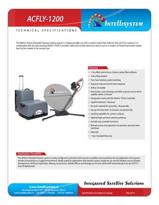
The iNetVu® Airline Checkable Flyaway antenna system is a highly portable unit with a 6-piece carbon fibre reflector that can fit in a suitcase. It is configurable with the auto-pointing iNetVu® 7024C Controller, cables and another electronic device such as a modem or PowerSmart power supply that can be installed in the second case.

Recommended
Recommended
More Related Content
What's hot
What's hot (18)
Similar to IT-ISS ACFLY-1200 - Intellisystem - Integrated Satellite Solutions
Similar to IT-ISS ACFLY-1200 - Intellisystem - Integrated Satellite Solutions (13)
More from Cristian Randieri PhD
More from Cristian Randieri PhD (20)
Recently uploaded
Recently uploaded (20)
IT-ISS ACFLY-1200 - Intellisystem - Integrated Satellite Solutions
- 1. www.intellisystem.it Via Augusto Murri N°1 - 96100 Siracusa (ITALY) info@intellisystem.it +39 (0)931-1756256 +39 335 1880035 Specifications are subject to change May 2016 T e c h n i c a l s p e c i f i c a t i o n s Integrated Satellite Solutions The iNetVu® Airline Checkable Flyaway antenna system is a highly portable unit with a 6-piece carbon fibre reflector that can fit in a suitcase. It is configurable with the auto-pointing iNetVu® 7024C Controller, cables and another electronic device such as a modem or PowerSmart power supply that can be installed in the second case. Application Versatility The Airline Checkable Flyaway system is easily configured to provide instant access to satellite communications for any application that requires remote connectivity in a rugged environment. Ideally suited for applications that require a quick, simple set-up; vertical markets such as Disaster Management, Oil & Gas Exploration, Mining, Construction, Mobile Offices and Emergency Services will benefit tremendously from the ACFLY’s ease of deployment. Features • 1.2m offset, prime focus, 6-piece carbon fibre reflector • 3 Axis Motorization • Two Case Solution, patent pending • Supports manual control when required • Airline checkable • One button, auto-pointing controller acquires any Ku-band satellite within 2 minutes • Designed to work with the iNetVu® 7024C Controller • Captive hardware / fasteners • No tools required for assembly / disassembly • Set-up time less than 10 minutes, one person job • Leveling capability for uneven surfaces • Optimal high-precision antenna pointing • Includes jog controller functions • Remote access and operation via network, web and other interfaces • Patented • 1Year StandardWarranty ACFLY-1200
- 2. www.intellisystem.it Via Augusto Murri N°1 - 96100 Siracusa (ITALY) info@intellisystem.it +39 (0)931-1756256 +39 335 1880035 Specifications are subject to change May 2016 T e c h n i c a l s p e c i f i c a t i o n s Integrated Satellite Solutions ACFLY-1200 Motors Electrical Interface 24VDC 5 Amp (Max.) Cases Case1: 6-piece antenna platform 48.5 x 71 x 39 cm (19”x 28”x 15.3”), 32 kg (70 lbs) Case 2: 3U Rack mount including iNetVu® 7024 Controller + feed + cables: 48.5 x 71 x 39 cm (19”x 28”x 15.3”), 32 kg (70 lbs) Case 3 (Optional): 4U Rack mount 62.2 x 34.3 x 47.6 cm (24.5”x 13.5”x 18.8”),10.7 kg (23.5 lbs) Ku-Band (Linear) Transmit Power 1 to 200 watt Feed 2 Port XPol Receive Transmit Frequency (GHz) 10.70 - 12.75 (1) 13.75 - 14.50 Feed Interface WR75 WR75 Efficiency 70% 70% Midband Gain (± .2 dBi) 41.50 43.00 Antenna NoiseTemp. (K) 10º EL= 45 / 30º EL= 24 Sidelobe Envelope Co-Pol (dBi) 1.5º<Θ<20º 29-25 Log Θ 20º<Θ<26.3º -3.5 26.3º<Θ<48º 32-25 Log Θ 48º<Θ -10Typical Cross-Polarization on Axis >35 dB Within 1dB Beamwidth >30 dB Return Loss 17.7 dB typ. 20 dB typ. Insertion Loss 0.3 dB typ. 0.1 dB typ. Tx/Rx Isolation 40 dB 90 dB VSWR 1.3:1 1.3:1 Shipping Weights & Dimensions* Platform Case: 74 cm x 43 cm x 51 cm (29’’x 17’’x 20’’), 34 kg (75 lbs) Controller Case: 74 cm x 43 cm x 51 cm (29’’x 17’’x 20’’), 34 kg (75 lbs) Mechanical Reflector 1.2m Offset Feed, carbon fibre Platform Geometry Elevation over Azimuth Offset Angle 15º Antenna Optics Single Offset Azimuth ± 180º Elevation 10º - 90º Polarization ± 95º Elevation Deploy Speed Variable 2º /sec typ. Azimuth Deploy Speed Variable 5º /sec typ. Peaking Speed 0.1 /sec Environmental Wind loading Operational With Ballast / Anchors 50 km/h (31 mph) Survival 145 km/h (90 mph) Temperature Operational -30º to 55º C (-22º to 131º F) Solar Radiation 360 BTU/h/sq. ft. Rain 1.3cm/h (0.51 in/h) Vibration per MIL-STD-810F, Annex A, Category 4,Truck/trailer/tracked ShockTest per IEC 60068-2-27 BumpTest per IEC 60068-2-29 Drop andTopple per IEC 60068-2-31 Free- Fall Drop per IEC 60068-2-32, and ISTA 1A Dust andWater Ingress per IEC 60529, IP66 Electrical Rx Tx Cables 2 RG6 Cables -10m (33 ft) each Control Cables Standard 10m (33 ft) Ext. Cable Optional Up to 60m (200 ft) available RF Interface Radio Mounting Back of Reflector AxisTransition Rigid +Twist-flex Guide Waveguide WR75 Cover Flange Interface Coaxial RG6U FType Note: (1) LNB PLLType required with stability better than ± 25 KHz *The shipping weights/dims can vary for particular shipments depending on actual system configuration, quantity, packaging materials and special requirements