KM5S LCD is a professional-grade display for electric PAS bikes. It has USB charging function giving full consideration to the needs of users experience when they ride. It has all our present functions to meet customers DIY needs and personalized requirements. It perfectly solved the water-proof problem with integrated key structure. It has metal frame appearance. It is widely recognized when it launched.
KM5S-U LDC Display products are made of PC plastic. This material ensures normal operation & robust mechanical performance in the temperature range of -20℃ to 60℃.
Model: KM5S-U LCD Display
Size: 88.75mm*50.3mm*47.9mm
Function: PAS Level; Speed; Trip/ODO; Headlight;
Walk/PAS Select/Error Alarm
Communication: UART Default/CAN
Holder: 22.2mm;25.4mm;31.8mm
Voltage: 24V/36V/31.8V
Certificate: CE/ROHS/IP65
Visit us by:
Website: https://www.king-meter.com
LinkedIn: https://www.linkedin.com/company/kingmeter
Facebook: https://www.facebook.com/KingMeterTech
Spain to be banned from participating in Euro 2024.docx
KM5S-U LCD Display CE Certification King-Meter Technology Co.,Ltd
1. Shenzhen GSI Technology Co., Ltd
Report No: GSI130103033001 Date of Issue: January 10, 2013
Page 1 of 40
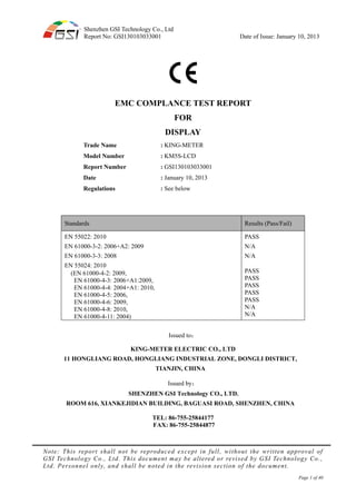
EMC COMPLANCE TEST REPORT
FOR
DISPLAY
Trade Name
Model Number
Report Number
Date
Regulations
: KING-METER
: KM5S-LCD
: GSI130103033001
: January 10, 2013
: See below
Standards Results (Pass/Fail)
EN 55022: 2010
EN 61000-3-2: 2006+A2: 2009
EN 61000-3-3: 2008
PASS
N/A
N/A
EN 55024: 2010
(EN 61000-4-2: 2009,
EN 61000-4-3: 2006+A1:2009,
EN 61000-4-4: 2004+A1: 2010,
EN 61000-4-5: 2006,
EN 61000-4-6: 2009,
EN 61000-4-8: 2010,
EN 61000-4-11: 2004)
PASS
PASS
PASS
PASS
PASS
N/A
N/A
Issued to:
KING-METER ELECTRIC CO., LTD
11 HONGLIANG ROAD, HONGLIANG INDUSTRIAL ZONE, DONGLI DISTRICT,
TIANJIN, CHINA
Issued by:
SHENZHEN GSI Technology CO., LTD.
ROOM 616, XIANKEJIDIAN BUILDING, BAGUASI ROAD, SHENZHEN, CHINA
TEL: 86-755-25844177
FAX: 86-755-25844877
Note: This report shall not be reproduced except in full, without the written approval of
GSI Technology Co., Ltd. This document may be altered or revised by GSI Technology Co.,
Ltd. Personnel only, and shall be noted in the revision section of the document.
2. Shenzhen GSI Technology Co., Ltd
Report No: GSI130103033001 Date of Issue: January 10, 2013
Page 2 of 40
TABLE OF CONTENT
Test Report Declaration Page
1. GENERAL INFORMATION ...................................................................................................................... 5
1.1 Description of Device (EUT).............................................................................................................. 5
1.2 Test Facility ......................................................................................................................................... 6
2. TEST INSTRUMENT USED...................................................................................................................... 7
2.1 For Conducted Emission Test............................................................................................................ 7
2.2 For Radiated Emission Measurement .............................................................................................. 7
2.3 For Harmonic & Flicker Test ............................................................................................................ 7
2.4 For Electrostatic Discharge Immunity Test...................................................................................... 7
2.5 For RF EM Field Test......................................................................................................................... 8
2.6 For Electrical Fast Transient /Burst Immunity Test ....................................................................... 8
2.7 For Surge Immunity Test................................................................................................................... 8
2.8 For Injected Current Susceptibility Test .......................................................................................... 8
2.9 For Voltage Dips and Interruptions Test .......................................................................................... 9
3. POWER LINE CONDUCTED EMISSION TEST.................................................................................... 10
3.1 Block Diagram of Test Setup ........................................................................................................... 10
3.2 Test Standard .................................................................................................................................... 10
3.3 Power Line Conducted Emission Limit.......................................................................................... 10
3.4 EUT Configuration on Test.............................................................................................................. 10
3.5 Operating Condition of EUT........................................................................................................... 10
3.6 Test Procedure .................................................................................................................................. 10
3.7 Power Line Conducted Emission Test Results ................................................................................11
4. RADIATED EMISSION MEASUREMENT ............................................................................................ 12
4.1 Block Diagram of Test...................................................................................................................... 12
4.2 Radiated Emission Limit ................................................................................................................. 12
4.3 EUT Configuration on Measurement ............................................................................................. 12
4.4 Operating Condition of EUT........................................................................................................... 13
4.5. Test Procedure ................................................................................................................................. 13
4.6 Radiated Emission Noise Measurement Result ............................................................................. 13
5. ELECTROSTATIC DISCHARGE IMMUNITY TEST ............................................................................ 14
5.1 Block Diagram of Test Setup ........................................................................................................... 14
5.2 Test Standard .................................................................................................................................... 14
5.3 Severity Levels and Performance Criterion................................................................................... 14
5.4 EUT Configuration........................................................................................................................... 14
5.5 Operating Condition of EUT........................................................................................................... 14
5.6 Test Procedure .................................................................................................................................. 15
5.7 Test Results........................................................................................................................................ 15
6. RF EM FIELD TEST................................................................................................................................. 17
6.1 Block Diagram of Test Setup ........................................................................................................... 17
6.2 Test Standard .................................................................................................................................... 17
6.3 Severity Levels and Performance Criterion................................................................................... 17
6.4 EUT Configuration........................................................................................................................... 17
6.5 Operating Condition of EUT........................................................................................................... 17
6.6 Test Procedure .................................................................................................................................. 17
6.7 Test Results........................................................................................................................................ 17
7. ELECTRICAL FAST TRANSIENT/BURST IMMUNITY TEST............................................................ 17
7.1 Block Diagram of Test Setup ........................................................................................................... 17
7.2 Test Standard .................................................................................................................................... 17
7.3 Severity Levels and Performance Criterion................................................................................... 17
7.4 EUT Configuration........................................................................................................................... 17
3. Shenzhen GSI Technology Co., Ltd
Report No: GSI130103033001 Date of Issue: January 10, 2013
Page 3 of 40
7.5 Operating Condition of EUT........................................................................................................... 17
7.6 Test Procedure .................................................................................................................................. 17
7.7 Test Result ......................................................................................................................................... 17
8. SURGE IMMUNITY TEST ...................................................................................................................... 17
8.1 Block Diagram of Test Setup ........................................................................................................... 17
8.2 Test Standard .................................................................................................................................... 17
8.3 Severity Levels and Performance Criterion................................................................................... 17
8.4 EUT Configuration........................................................................................................................... 17
8.5 Operating Condition of EUT........................................................................................................... 17
8.6 Test Procedure .................................................................................................................................. 17
8.7 Test Result ......................................................................................................................................... 17
9. INJECTED CURRENTS SUSCEPTIBILITY TEST ................................................................................ 17
9.1 Block Diagram of Test Setup ........................................................................................................... 17
9.2 Test Standard .................................................................................................................................... 17
9.3 Severity Levels and Performance Criterion................................................................................... 17
9.4 EUT Configuration........................................................................................................................... 17
9.5 Operating Condition of EUT........................................................................................................... 17
9.6 Test Procedure .................................................................................................................................. 17
9.7Test Results......................................................................................................................................... 17
10.MAGNETIC FIELD SUSCEPTIBILITY TEST ...................................................................................... 17
10.1 Block Diagram of Test.................................................................................................................... 17
10.2 Test Standard .................................................................................................................................. 17
10.3 Severity Levels and Performance Criterion................................................................................. 17
10.4 EUT Configuration on Test............................................................................................................ 17
10.5 Test Procedure ................................................................................................................................ 17
10.6 Test Results...................................................................................................................................... 17
APPENDIX I (2 pages)
APPENDIX II (2 pages)
APPENDIX III (PHOTOS OF EUT) (3 pages)
4. Shenzhen GSI Technology Co., Ltd
Report No: GSI130103033001 Date of Issue: January 10, 2013
Page 4 of 40
TEST REPORT DESCRIPTION
Equipment Under Test
Trade Name
Model Number
Applicant
Address
Manufacturer
Address
Technical Standards
: DISPLAY
: KING-METER
: KM5S-LCD
: KING-METER ELECTRIC CO., LTD
: 11 HONGLIANG ROAD, HONGLIANG INDUSTRIAL ZONE,
DONGLI DISTRICT, TIANJIN, CHINA
: KING-METER ELECTRIC CO., LTD
: 11 HONGLIANG ROAD, HONGLIANG INDUSTRIAL ZONE,
DONGLI DISTRICT, TIANJIN, CHINA
: EN 55022: 2010
EN 55024: 2010
(EN 61000-4-2: 2009, EN 61000-4-3: 2006+A1:2009, EN 61000-4-4:
2004+A1: 2010, EN 61000-4-5: 2006, EN 61000-4-6: 2009)
Report Number
Date of Test
Deviation
Condition of Test Sample
: GSI130103033001
: January 03, 2013 to January 10, 2013
: None
: Normal
The product described above is tested by Shenzhen Emtek Co., Ltd. The measurement results are contained in
this test report and Shenzhen Emtek Co., Ltd assume full responsibility for the accuracy of the test results.
Also, this report shows that the EUT (Equipment Under Test) technically complies with the council the EMC
Directive 2004/108/EC requirements.
The test report is valid for above tested sample only and shall not be reproduced in part without written
approval of Shenzhen GSI Technology Co., Ltd.
Prepared by :
(John)
Approved & Authorized Signer:
(Morris)
5. Shenzhen GSI Technology Co., Ltd
Report No: GSI130103033001 Date of Issue: January 10, 2013
Page 5 of 40
1. GENERAL INFORMATION
1.1 Description of Device (EUT)
Applicant
Manufacturer
Report Number
Date of Test
Equipment under Test
Model Number
Power Supply
Test Voltage
Type of Test
Technical Standards
: KING-METER ELECTRIC CO., LTD
: KING-METER ELECTRIC CO., LTD
: GSI130103033001
: January 03, 2013 to January 10, 2013
: DISPLAY
: KM5S-LCD
: DC 36V
: DC 36V
: EMC Directive 2004/108/EC for CE Marking
: EN 55022: 2010
EN 55024: 2010
(EN 61000-4-2: 2009, EN 61000-4-3: 2006+A1:2009, EN 61000-4-4:
2004+A1: 2010, EN 61000-4-5: 2006, EN 61000-4-6: 2009)
Frequency Range
(EN55022)
Test Site
: 150 kHz to 30MHz for Line Conducted Test
30MHz to 1000MHz for Radiated Emission Measurement.
: Shenzhen Emtek Co., Ltd
Bldg. 69, Majialong, Taipinyang Industry Zone, Nanshan District,
Shenzhen, Guandong
6. Shenzhen GSI Technology Co., Ltd
Report No: GSI130103033001 Date of Issue: January 10, 2013
Page 6 of 40
1.2 Test Facility
Description: There is one 3m semi-anechoic chamber(966) test sites and one line
conducted labs for final test.
There is one 3m semi-anechoic and the Line Conducted labs are
constructed and calibrated to meet the FCC requirements in
documents ANSI C63.4: 2009 and EN 55022 requirements.
Site Filing: A site description is on file with the Federal Communications
Commission, 7435 Oakland Mills Road, Columbia, MD 21046.
Site Accreditation: Accredited by CNAS, 2012
Accredited by TUV. 2012
Instrument Tolerance: All measuring equipment is in accord with ANSI C63.4 and
EN55022 requirements that meet industry regulatory agency and
accreditation agency requirement.
Ground Plane: Two conductive reference ground planes were used during the Line Conducted
Emission, one in vertical and the other in horizontal. The dimensions of these ground planes are
as below. The vertical ground plane was placed distancing 40 cm to the rear of the wooden test
table on where the EUT and the support equipment were placed during test. The horizontal
ground plane projected 50 cm beyond the footprint of the EUT system and distanced 80 cm to the
wooden test table. For Radiated Emission Test, one horizontal conductive ground plane extended
at least 1m beyond the periphery of the EUT and the largest measuring antenna, and covered the
entire area between the EUT and the antenna. It has no holes or gaps having longitudinal
dimensions larger than one-tenth of a wavelength at the highest frequency of measurement up to
1GHz.
7. Shenzhen GSI Technology Co., Ltd
Report No: GSI130103033001 Date of Issue: January 10, 2013
Page 7 of 40
2. TEST INSTRUMENT USED
2.1 For Conducted Emission Test
Item Test Equipment Manufacturer Model No Serial NO. Cal.Date Due bate
1 EMI Test Receiver
ROHDE&
SCHWARZ
ESCS30 100343 11-8-2012 11-8-2013
2 LISN AFJ LS16 16010222119 11-8-2012 11-8-2013
2.2 For Radiated Emission Measurement
Item Test Equipment Manufacturer Model No Serial NO. Cal.Date Due bate
1 Spectrum Analyzer ANRITSU MS2661C 6200140915 11-8-2012 11-8-2013
2 Test Receiver Rohde & Schwarz ESCS30 828985/018 11-8-2012 11-8-2013
3 Bilog Antenna Schwarzbeck VULB9163 142 11-8-2012 11-8-2013
4 50 Coaxial Switch Anritsu Corp MP59B 6100237248 11-8-2012 11-8-2013
5 Cable Schwarzbeck
AK9513(1
m)
CR RX2 11-8-2012 11-8-2013
6 Spectrum Analyzer ANRITSU MS2661C 6200140915 11-8-2012 11-8-2013
7 Test Receiver Rohde & Schwarz ESCS30 828985/018 11-8-2012 11-8-2013
2.3 For Harmonic & Flicker Test
Item Test Equipment Manufacturer Model No Serial NO. Cal.Date Due bate
1
Power Frequency
System
HAEFELY PHF555 080419-03 11-8-2012 11-8-2013
2.4 For Electrostatic Discharge Immunity Test
Item Test Equipment Manufacturer Model No Serial NO. Cal.Date Due bate
1
HAEFELY ESD
TESTER
EM Test PESD 1600 302105 11-8-2012 11-8-2013
8. Shenzhen GSI Technology Co., Ltd
Report No: GSI130103033001 Date of Issue: January 10, 2013
Page 8 of 40
2.5 For RF EM Field Test
Item Test Equipment Manufacturer Model No Serial NO. Cal.Date Due bate
1 Signal Generator Maconi 2022D 119246/003 11-8-2012 11-8-2013
2 Power Amplifier M2S
A00181/
1000
9801-112 11-8-2012 11-8-2013
3 Power Amplifier M2S
AC8113
/800-25
0A
9801-179 11-8-2012 11-8-2013
4 Power Antenna SCHAFFNER
CBL614
0A
1240 11-8-2012 11-8-2013
2.6 For Electrical Fast Transient /Burst Immunity Test
Item Test Equipment Manufacturer Model No Serial NO. Cal.Date Due bate
1
Fast
Transients/Burst
Generator
SCHAFFNER
Modula
6000
34354 11-8-2012 11-8-2013
2.7 For Surge Immunity Test
Item Test Equipment Manufacturer Model No Serial NO. Cal.Date Due bate
1 Surge Tester HAEFELY
PSURGE4.
1
080107-04 11-8-2012 11-8-2013
2.8 For Injected Current Susceptibility Test
Item Test Equipment Manufacturer Model No Serial NO. Cal.Date Due bate
1 Simulator EMTEST CWS500C 0900-12 11-8-2012 11-8-2013
2 CDN EMTEST CDN-M2 5100100100 11-8-2012 11-8-2013
3 CDN EMTEST CDN-M3 0900-11 11-8-2012 11-8-2013
4 Injection Clamp EMTEST
F-2031-23
MM
368 11-8-2012 11-8-2013
5 Attenuator EMTEST ATT6 0010222A 11-8-2012 11-8-2013
9. Shenzhen GSI Technology Co., Ltd
Report No: GSI130103033001 Date of Issue: January 10, 2013
Page 9 of 40
2.9 For Voltage Dips and Interruptions Test
Item Test Equipment Manufacturer Model No Serial NO. Cal.Date Due bate
1 Dips Tester HAEFELY Pline1610 083732-12 11-8-2012 11-8-2013
10. Shenzhen GSI Technology Co., Ltd
Report No: GSI130103033001 Date of Issue: January 10, 2013
Page 10 of 40
3. POWER LINE CONDUCTED EMISSION TEST
3.1 Block Diagram of Test Setup
3.2 Test Standard
EN 55022: 2010
3.3 Power Line Conducted Emission Limit
Limits dB(μV)Frequency
MHz Quasi-peak Level Average Level
0.15 ~ 0.50 66 ~ 56* 56 ~ 46*
0.50 ~ 5.00 56 46
5.00 ~ 30.00 60 50
Notes: 1. *Decreasing linearly with logarithm of frequency.
2. The lower limit shall apply at the transition frequencies.
3.4 EUT Configuration on Test
The equipments are installed on conducted emission test to meet EN 55022 requirement and operating
in a manner which tends to maximize its emission characteristics in a normal application.
3.5 Operating Condition of EUT
3.5.1 Setup the EUT and simulators as shown in Section 3.1.
3.5.2 Turn on the power of all equipments.
3.5.3 Let the EUT work in test mode and test it.
3.6 Test Procedure
The EUT is put on the ground and connected to the DC mains through a Artificial Mains Network
(AMN). This provided a 50ohm coupling impedance for the tested equipments. Both sides of AC line
are checked to find out the maximum conducted emission levels according to the EN55022
regulations during conducted emission test.
The bandwidth of the test receiver is set at 9KHz.
The frequency range from 150 KHz to 30 MHz is investigated.
The test results are listed in Section 3.7 and the scanning waveforms of the test mode are attached
within Appendix I.
DC Mains
L.I.S.N
Test Receiver
EUT
11. Shenzhen GSI Technology Co., Ltd
Report No: GSI130103033001 Date of Issue: January 10, 2013
Page 11 of 40
3.7 Power Line Conducted Emission Test Results
PASS.
The frequency range 150KHz to 30MHz is investigated.
Please refer to Appendix I.
12. Shenzhen GSI Technology Co., Ltd
Report No: GSI130103033001 Date of Issue: January 10, 2013
Page 12 of 40
4. RADIATED EMISSION MEASUREMENT
4.1 Block Diagram of Test
4.1.1 Block diagram of connection between the EUT and simulators
DC Mains
4.1.2 Anechoic Chamber Test Setup Diagram
4.2 Radiated Emission Limit
Limits:
All emanations from a class B device or system, including any network of conductors and apparatus
connected thereto, shall not exceed the level of field strengths specified below:
FREQUENCY DISTANCE FIELD STRENGTHS LIMIT
(MHz) (Meters) (dBμV/m)
30 ~ 230 3 40
230 ~ 1000 3 47
Note: (1) The smaller limit shall apply at the combination point between two frequency bands.
(2) Distance refers to the distance in meters between the measuring instrument antenna and
the closed point of any part of the EUT.
4.3 EUT Configuration on Measurement
The equipments are installed on Radiated Emission Measurement to meet the commission
requirements and operating regulations in a manner which tends to maximize its emission
characteristics in normal application.
1m to 4m
Spectrum
Analyzer
EUT
3m
0.8m
Turntable
Coaxial CableGround Plane
EUT
13. Shenzhen GSI Technology Co., Ltd
Report No: GSI130103033001 Date of Issue: January 10, 2013
Page 13 of 40
4.4 Operating Condition of EUT
4.4.1 Setup the EUT as shown in Section 4.1.
4.4.2 Let the EUT work in test mode and measure it.
4.5. Test Procedure
EUT and its simulators are placed on a turntable, which is 0.8 meter high above ground. The
turntable can rotate 360 degrees to determine the position of the maximum emission level. EUT is
set 3.0 meters away from the receiving antenna, which is mounted on a antenna tower. The antenna
can be moved up and down between 1.0 meter and 4 meters to find out the maximum emission level.
Broadband antenna (calibrated bilog antenna) is used as receiving antenna. Both horizontal and
vertical polarization of the antenna is set on measurement. In order to find the maximum emission
levels, all of the interface cables must be manipulated according to ANSI C63.4 on radiated
emission measurement.
The bandwidth of the EMI test receiver is set at 120KHz.
The frequency range from 30MHz to 1000MHz is checked.
All the test modes are tested and all the scanning waveforms are attached in Appendix II.
4.6 Radiated Emission Noise Measurement Result
PASS.
The frequency range from 30MHz to 1000MHz is investigated.
Please reference to Appendix II.
14. Shenzhen GSI Technology Co., Ltd
Report No: GSI130103033001 Date of Issue: January 10, 2013
Page 14 of 40
5. ELECTROSTATIC DISCHARGE IMMUNITY TEST
5.1 Block Diagram of Test Setup
5.1.1 Block Diagram of the EUT and the simulators
DC Mains
5.1.2 Test Setup
5.2 Test Standard
EN 55024: 2010,
(EN 61000-4-2: 2009 Severity Level: 3 / Air Discharge: ±8KV
Level: 2 / Contact Discharge: ±4KV)
5.3 Severity Levels and Performance Criterion
5.3.1 Severity level
Level Test Voltage
Contact Discharge (KV)
Test Voltage
Air Discharge (KV)
1. ±2 ±2
2. ±4 ±4
3. ±6 ±8
4. ±8 ±15
X Special Special
5.3.2 Performance criterion: B
5.4 EUT Configuration
The configurations of EUT is listed in Section 3.4.
5.5 Operating Condition of EUT
Same as conducted emission measurement, which is listed in Section 3.5 except the test set up was
replaced by Section 7.1.
EUT
AC Mains
ESD
Tester
0.8 m
EUT
15. Shenzhen GSI Technology Co., Ltd
Report No: GSI130103033001 Date of Issue: January 10, 2013
Page 15 of 40
5.6 Test Procedure
5.6.1 Air Discharge:
This test is done on a non-conductive surface. The round discharge tip of the discharge
electrode shall be approached as fast as possible to touch the EUT. After each discharge, the
discharge electrode shall be removed from the EUT. The generator is then re-triggered for a
new single discharge and repeated 10 times for each pre-selected test point. This procedure
shall be repeated until all the air discharge completed.
5.6.2 Contact Discharge:
All the procedure shall be same as Section 5.6.1. Except that the tip of the
discharge electrode shall touch the EUT before the discharge switch is operated.
5.6.3 Indirect discharge for horizontal coupling plane
At least 10 single discharges (in the most sensitive polarity) shall be applied at the front edge
of each HCP opposite the center point of each unit (if applicable) of the EUT and 0.1m from
the front of the EUT. The long axis of the discharge electrode shall be in the plane of the HCP
and perpendicular to its front edge during the discharge.
5.6.4 Indirect discharge for vertical coupling plane
At least 10 single discharges (in the most sensitive polarity) shall be applied to the center of
one vertical edge of the coupling plane. The coupling plane, of dimensions 0.5m X 0.5m, is
placed parallel to, and positioned at a distance of 0.1m from the EUT. Discharges shall be
applied to the coupling plane, with this plane in sufficient different positions that the four
faces of the EUT are completely illuminated.
5.7 Test Results
PASS.
Please refer to the following pages.
16. Shenzhen GSI Technology Co., Ltd
Report No: GSI130103033001 Date of Issue: January 10, 2013
Page 16 of 40
ELECTROSTATIC DISCHARGE TEST RESULTS
EUT : DISPLAY
Model Number : KM5S-LCD
Temperature : 25℃ Humidity : 50%
Air Discharge: ± 8KV
Contact Discharge: ± 4KV # For each point positive 10 times and negative 10 times discharge
Location
Kind
A-Air Discharge
C-Contact Discharge
Result
Metal shell C PASS
Screws C PASS
Ports C PASS
HCP C PASS
VCP of the front C PASS
VCP of the rear C PASS
VCP of the left C PASS
VCP of the right C PASS
Note:
Discharge should be considered on Contact and Air and Horizontal Coupling Plane (HCP) and Vertical
Coupling Plane (VCP).
17. Shenzhen GSI Technology Co., Ltd
Report No: GSI130103033001 Date of Issue: January 10, 2013
Page 17 of 40
6. RF EM FIELD TEST
6.1 Block Diagram of Test Setup
6.1.1 Block Diagram of the EUT and the simulators
DC Mains
6.1.2 R/S Test Setup
6.2 Test Standard
EN 55024: 2010 (EN 61000-4-3: 2006+A1: 2009, Severity Level: 2, 3V / m)
0.8m
Signal
Generator
EUT Monitoring by
using a camera
Control Room
7x4x3Chamber
EUT & Support
Units
PC Controller to
control S.G. & PA as
well as forward power
3 meter
1.5 meter
Power
Amplifier
EUT
18. Shenzhen GSI Technology Co., Ltd
Report No: GSI130103033001 Date of Issue: January 10, 2013
Page 18 of 40
6.3 Severity Levels and Performance Criterion
6.3.1 Severity level
Level Field Strength V/m
1 1
2 3
3 10
X Special
6.3.2 Performance criterion: A
6.4 EUT Configuration
The configurations of EUT are listed in Section 3.4.
6.5 Operating Condition of EUT
6.5.1 Setup the EUT as shown in Section 6.1.
6.5.2 Turn on the power of all equipments.
6.5.3 Let the EUT work in test modes and measure it.
6.6 Test Procedure
The EUT and its simulators are placed on a turn table which is 0.8 meter above ground. EUT is set 3
meter away from the transmitting antenna which is mounted on an antenna tower. Both horizontal
and vertical polarization of the antenna are set on test. Each of the four sides of EUT must be faced
this transmitting antenna and measured individually.
All the scanning conditions are as follows:
Condition of Test Remarks
----------------------------------------- ----------------------------------------
1. Fielded Strength 3 V/m (Severity Level 2)
2. Radiated Signal Modulated
3. Scanning Frequency 80 - 1000 MHz
4. Dwell time of radiated 0.0015 decade/s
5. Waiting Time 1 Sec.
6.7 Test Results
PASS.
Please refer to the following page.
19. Shenzhen GSI Technology Co., Ltd
Report No: GSI130103033001 Date of Issue: January 10, 2013
Page 19 of 40
RF EM FIELD TEST RESULTS
EUT : DISPLAY
Model Number : KM5S-LCD
Temperature : 25℃ Humidity : 50%
Modulation: AM 1KHz 80%
Frequency Rang: 80-1000MHz
Steps 1 %
Horizontal Vertical
Front PASS PASS
Right PASS PASS
Rear PASS PASS
Left PASS PASS
Note:
20. Shenzhen GSI Technology Co., Ltd
Report No: GSI130103033001 Date of Issue: January 10, 2013
Page 20 of 40
7. ELECTRICAL FAST TRANSIENT/BURST IMMUNITY
TEST
7.1 Block Diagram of Test Setup
7.1.1 Block Diagram of the EUT
DC Mains
7.1.2 Block Diagram of the AC Mains
7.2 Test Standard
EN 55024: 2010 (EN 61000-4-4: 2004+A1: 2010, Severity Level, Level 2: 1KV )
7.3 Severity Levels and Performance Criterion
7.3.1 Severity level
7.3.2 Performance criterion: B
7.4 EUT Configuration
The configurations of EUT are listed in Section 3.4.
7.5 Operating Condition of EUT
7.5.1 Setup the EUT as shown in Section 7.1.
7.5.2 Turn on the power of all equipments.
7.5.3 Let the EUT work in test modes and measure it.
Open Circuit Output Test Voltage ± 10%
Level On Power Supply Lines On I/O (Input/Output) Signal data
and control lines
1 0.50 KV 0.25 KV
2 1.00KV 0.50 KV
3 2.00KV 1.00KV
4 4.00KV 2.00 KV
X Special Special
0.1m DC Mains
EUT EFT/B Tester
EUT
21. Shenzhen GSI Technology Co., Ltd
Report No: GSI130103033001 Date of Issue: January 10, 2013
Page 21 of 40
7.6 Test Procedure
The EUT is put on the table which is 0.8 meter high above the ground. This reference ground plane
shall project beyond the EUT by at least 0.1m on all sides and the minimum distance between EUT
and all other conductive structure, except the ground plane beneath the EUT, shall be more than
0.5m.
7.6.1 For input and output AC power ports:
It’s unnecessary to test.
7.6.2 For signal lines ports:
It’s unnecessary to test.
7.6.3 For DC ports:
The EUT is connected to the power mains by using a coupling device which couples the EFT
interference signal to DC power lines. Both polarities of the test voltage should be applied
during compliance test and the duration of the test is 2 mins.
7.7 Test Result
PASS.
Please refer to the following pages
22. Shenzhen GSI Technology Co., Ltd
Report No: GSI130103033001 Date of Issue: January 10, 2013
Page 22 of 40
ELECTRICAL FAST TRANSIENT/BURST TEST RESULTS
Standard : EN 61000-4-4 Result : PASS / FAIL
EUT : DISPLAY
Model Number : KM5S-LCD
Temperature : 25℃ Humidity: 50%
Line : DC Mains Line : Signal line
Coupling : Direct Coupling : Capacitive
Test Time : 120s
Line Test Voltage Result(+) Result(-)
L
N
PE
L、N
L、PE
N、PE
L、N、PE
Signal line
DC line 1KV PASS PASS
Note:
23. Shenzhen GSI Technology Co., Ltd
Report No: GSI130103033001 Date of Issue: January 10, 2013
Page 23 of 40
8. SURGE IMMUNITY TEST
8.1 Block Diagram of Test Setup
8.1.1 Block Diagram of the EUT
DC Mains
8.1.2 Surge Test Setup
8.2 Test Standard
EN 55024: 2010 (EN 61000-4-5: 2006)
Severity Level: Line to Line: Level 1, 0.5KV
8.3 Severity Levels and Performance Criterion
8.3.1 Severity level
Severity Level Open-Circuit Test Voltage
KV
1
2
3
4
*
0.5
1.0
2.0
4.0
Special
8.3.2 Performance criterion: B
8.4 EUT Configuration
The configuration of EUT is listed in Section 3.3.
0.8 m AC Mains
EUT
DC Mains
Surge Tester
EUT
24. Shenzhen GSI Technology Co., Ltd
Report No: GSI130103033001 Date of Issue: January 10, 2013
Page 24 of 40
8.5 Operating Condition of EUT
8.5.1 Setup the EUT as shown in Section 8.1.
8.5.2 Turn on the power of all equipments.
8.5.3 Let the EUT work in test mode and measure it.
8.6 Test Procedure
8.6.1 Set up the EUT and test generator as shown on Section 8.1.2.
8.6.2 For line to line coupling mode, provide a 0.5 KV 1.2/50us voltage surge
(at open-circuit condition) and 8/20us current surge to EUT selected points.
8.6.3 At least 5 positive and 5 negative (polarity) tests with a maximum 1/min repetition rate are
conducted during test.
8.6.4 Different phase angles are done individually.
8.6.5 Record the EUT operating situation during compliance test and decide the EUT immunity
criterion for above each test.
8.7 Test Result
PASS.
Please refer to the following page.
25. Shenzhen GSI Technology Co., Ltd
Report No: GSI130103033001 Date of Issue: January 10, 2013
Page 25 of 40
SURGE IMMUNITY TEST RESULT
EUT : DISPLAY
Model Number : KM5S-LCD
Temperature : 22℃ Humidity : 50%
Location Polarity Phase Angle Number of
Pulse
Pulse Voltage (KV) Result
Line+ to Line- + 0o
5 0.5 PASS
- 0o
5 0.5 PASS
L-PE
N-PE
Remark: Test Equipment :
Surge Tester Psurge4.1
26. Shenzhen GSI Technology Co., Ltd
Report No: GSI130103033001 Date of Issue: January 10, 2013
Page 26 of 40
9. INJECTED CURRENTS SUSCEPTIBILITY TEST
9.1 Block Diagram of Test Setup
9.1.1 Block Diagram of the EUT
9.1.2 Block Diagram of Test Setup
9.2 Test Standard
EN 55024: 2010
(EN 61000-4-6: 2009, Severity Level: Level 2, 3V (rms), (0.15MHz ~ 80MHz)
9.3 Severity Levels and Performance Criterion
9.3.1 Severity level
9.3.2 Performance criterion: A
9.4 EUT Configuration
The configuration of EUT is listed in Section 3.3.
Level Field Strength V
1 1
2 3
3 10
X Special
Ground Reference Support
EUT
CDN DC Mains
Signal
Generator
Power
Amplifier
0.1 m
DC Mains
EUT
27. Shenzhen GSI Technology Co., Ltd
Report No: GSI130103033001 Date of Issue: January 10, 2013
Page 27 of 40
9.5 Operating Condition of EUT
9.5.1 Setup the EUT as shown in Section 9.1.
9.5.2 Turn on the power of all equipments.
9.5.3 Let the EUT work in test mode and measure it.
9.6 Test Procedure
9.6.1 Set up the EUT, CDN and test generators as shown on Section 9.1.2.
9.6.2 Let the EUT work in test mode and measure it.
9.6.3 The EUT are placed on an insulating support 0.1m high above a ground reference plane.
CDN (coupling and decoupling device) is placed on the ground plane about 0.3m from
EUT. Cables between CDN and EUT are as short as possible, and their height above the
ground reference plane shall be between 30 and 50 mm (where possible).
9.6.4 The disturbance signal described below is injected to EUT through CDN.
9.6.5 The EUT operates within its operational mode(s) under intended climatic conditions after
power on.
9.6.6 The frequency range is swept from 150KHz to80MHz using 3V signal level, and with the
disturbance signal 80% amplitude modulated with a 1KHz sine wave.
9.6.7 The rate of sweep shall not exceed 1.5*10-3decades/s. Where the frequency is swept
incrementally, the step size shall not exceed 1% of the start and thereafter 1% of the
preceding frequency value.
9.6.8 Recording the EUT operating situation during compliance testing and decide the EUT
immunity criterion.
9.7Test Results
PASS.
Please refer to the following page.
28. Shenzhen GSI Technology Co., Ltd
Report No: GSI130103033001 Date of Issue: January 10, 2013
Page 28 of 40
INJECTED CURRENTS SUSCEPTIBILITY TEST RESULTS
EUT : DISPLAY
Model Number : KM5S-LCD
Temperature : 22℃ Humidity : 50%
Frequency Range
(MHz)
Injected Position Strength
(Unmodulated)
Criterion Result
0.15 ~ 80 DC Mains 3V A PASS
Test Mode:
Frequency Range
(MHz)
Injected Position Strength
(Unmodulated)
Criterion Result
Remark : 1. Modulation Signal:1KHz 80% AM
Measurement Equipment :
Simulator: CWS 500 (SWITZERLAND EMTEST)
CDN : CDN-M2 (SWITZERLAND EMTEST)
CDN-M3 (SWITZERLAND EMTEST)
Note:
29. Shenzhen GSI Technology Co., Ltd
Report No: GSI130103033001 Date of Issue: January 10, 2013
Page 29 of 40
10.MAGNETIC FIELD SUSCEPTIBILITY TEST
10.1 Block Diagram of Test
10.1.1 Block diagram of test setup
10.1.2 Magnetic field test setup
10.2 Test Standard
EN 55024: 2010 (EN 61000-4-8: 2010, Severity Level: Level 1, 1A / m)
10.3 Severity Levels and Performance Criterion
10.3.1 Severity Levels
Level Field Strength A/m
1 1
2 3
3 10
4 30
5 100
X Special
10.3.2 Performance Criterion: A
10.4 EUT Configuration on Test
The configuration of the EUT is same as Section 3.3.
Ground Reference Support
EUT
AC Mains0.1 m
Magnetic Field
Tester
AC
Transformer
Wood
Induction Coil
DC Mains
EUT
30. Shenzhen GSI Technology Co., Ltd
Report No: GSI130103033001 Date of Issue: January 10, 2013
Page 30 of 40
10.5 Test Procedure
The EUT is placed in the middle of a induction coil (1*1m), under which is a 1*1*0.1m (high)
table, this small table is also placed on a larger table, 0.8 m above the ground. The X, Y and Z
polarization of the induction coil is set on test, so that each side of the EUT is affected by the
magnetic field. Also can reach the same aim by change the position of the EUT.
10.6 Test Results
Note: Not applicant, because no any component can be influenced by power magnetic field.
31. Shenzhen GSI Technology Co., Ltd
Report No: GSI130103033001 Date of Issue: January 10, 2013
Page 31 of 40
APPENDIX I
32. Shenzhen GSI Technology Co., Ltd
Report No: GSI130103033001 Date of Issue: January 10, 2013
Page 32 of 40
Test Mode: On
33. Shenzhen GSI Technology Co., Ltd
Report No: GSI130103033001 Date of Issue: January 10, 2013
Page 33 of 40
Test Mode: On
34. Shenzhen GSI Technology Co., Ltd
Report No: GSI130103033001 Date of Issue: January 10, 2013
Page 34 of 40
APPENDIX II
35. Shenzhen GSI Technology Co., Ltd
Report No: GSI130103033001 Date of Issue: January 10, 2013
Page 35 of 40
Test Mode: On
36. Shenzhen GSI Technology Co., Ltd
Report No: GSI130103033001 Date of Issue: January 10, 2013
Page 36 of 40
Test Mode: On
37. Shenzhen GSI Technology Co., Ltd
Report No: GSI130103033001 Date of Issue: January 10, 2013
Page 37 of 40
APPENDIX III
(PHOTOS OF EUT)
38. Shenzhen GSI Technology Co., Ltd
Report No: GSI130103033001 Date of Issue: January 10, 2013
Page 38 of 40
39. Shenzhen GSI Technology Co., Ltd
Report No: GSI130103033001 Date of Issue: January 10, 2013
Page 39 of 40
40. Shenzhen GSI Technology Co., Ltd
Report No: GSI130103033001 Date of Issue: January 10, 2013
Page 40 of 40