2. Contents
1. AIMS AND MOTIVATION.....................................................................................................................1
2. CONCEPT.............................................................................................................................................1
3. TECHNICAL DEVELOPMENT.................................................................................................................2
3.1 Mechanical Development.............................................................................................................2
3.2 Electrical Design............................................................................................................................3
4. FUTURE WORKS ..................................................................................................................................5
5. CONCLUSION.......................................................................................................................................5
6. REFERENCES........................................................................................................................................6
7. APPENDIX............................................................................................................................................7
7.1 Appendix A – Mechanical..............................................................................................................7
7.2 Appendix B - Electrical ................................................................................................................10
7.3 Appendix C - Software.................................................................................................................16
1. AIMS AND MOTIVATION
Stroke, being the second most common cause of death and the main cause of disability in the UK [1],
is estimated to have a total cost of £ 7 billion a year. [2] There has been a large demand of therapy
hours with post-stroke rehabilitation. After discussion with the therapist, we found that for post-
stroke rehabilitation, the first 6 months period is crucial as this is the period when neuroplasticity is
maintained at a high level and regaining of neurofunction can be effectively achieved through training.
However, there is also a huge demand for therapy hours for early stage patients. Therefore, we
planned to design a rehabilitation device that targets early stage patients whilst also incorporating
flexibility to accommodate a relatively wide target range for late stage patients with greater mobility.
In addition, we plan to motivate the patients and increase their focus throughout the rehabilitation
session by integrating it with an interactive game.
2. CONCEPT
We decided to adopt a game based on “Bejeweled” [3], where the user is supposed to swap pairs of
gems in order to create sets of 3 or more identical gems in a straight line. The game consists of an 8x8
board grid filled with gems. When a set of gems is matched, they will disappear to create an empty
space. Thereafter, more gems will fall into the board from above to fill in these spaces.
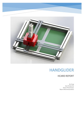
Our device, the HandGlider, will include a handle, to be moved by the patients, which translates their
2D upper limb motion into the swapping or moving of the gems. This handle will be a grippable joystick
which allows translational (but not rotational) movement. This will include a “restricted mode” where
the patients’ movement is restricted to left/right and upward/downward motion, and a “unrestricted
mode” where they are allowed to move anywhere within in the 2D plane. In both cases, the patients
would have to return to a centre position before they can trigger another command for the gem
movement.
3. The HandGlider is designed to primarily be used alongside a therapist, however, it would be portable
and cost effective so that it can be used domestically if needed. The product also aims to enhance the
number of patients able to use the device by being compatible with an arm support [4]. In addition,
for patients who lack grip strength to operate the device, a velcro wrist support will be used to attach
the hand onto the handle.
3. TECHNICAL DEVELOPMENT
3.1 Mechanical Development
We decided to make a device that trains translational motion of the arm using a handle, guided paths
and frames. Our initial concept features 4 Flexlink beams defining the 4 boundaries of our device. In
the square area enclosed by the 4 beams, we have a square aluminium sheet with cross-shaped cut-
through paths. The handle is attached onto the device at the cut-out path in such a way that allows it
to be moved along the path. In this way, the motion of the handle is restricted by the cut-out path on
the metal sheet and hence we achieve a restricted motion for the handle. The novelty of this concept
is that the guided path is only limited to the cut-out shape on the metal. I.e. Figure 1 shows a vertical
and horizontal guided path whereas Figure 2 shows how the cut-out can be modified to accommodate
a diagonal guided path.
Although implementing restricted motion is very important to patients with low-level control, this
concept takes the rehabilitation a step further by also allowing unrestricted motion to any point in the
2D plane of the device. This is an additional feature which allows continued rehabilitation for patients
who require high-level training and adds value to the product. In order to achieve the unrestricted
motion, the handle is detached and the device is simply flipped over. Once flipped, two independent
rectangular aluminium sheets are attached as seen in Figure 3. As one sheet goes horizontally and the
other goes vertically, we planned to use T-slot sliders to attach each aluminium sheet to a pair of
parallel Flexlink beams. This would ensure that the 2 aluminium sheets are free to move in their
respective orthogonal directions. The handle is attached at the point of intersection of the 2
aluminium sheets as this point can span throughout the whole plane. This concept was further
developed by eliminating the need to flip the device and attaching the guiding supports directly on
top, as seen on Figure 4.
After some prototyping, we found that there were major problems with both the unrestricted case
and the handle attachment. For the unrestricted case, we found the movement of the 2 independent
sheets were extremely discontinuous. Due to the nature of the materials and the geometry of the
aluminium sheet, the resources available in the workshop did not allow us to manufacture with very
high precision. This lack of precision led to the attachment of the sheet to the flexlink beam being
slightly loose. This in turn caused the T-slot sliders at each end to move at different speeds creating
movement which was not parallel. In addition to translational motion, rotary motion is also observed
which exerts a tension to the 2 sliders and increases friction dramatically.
For the handle attachment, the problem occurs for both restrained and unrestrained motion. Since
there is only one point where the handle goes through the hole on the sheet, rotation of the handle
is not restricted. Thus, in addition to the translational movement, the user can move their wrist and
rotate the handle during their training. This will cause training of wrong postures and have
deteriorating effect on the rehabilitation process.
Realising the drawbacks of the previous design, we decided to target the friction and the misalignment
specifically for improvement. To demonstrate the functionality of the concept, sliders with ball
bearings and pre-made tracks were used. In order to fix the tracks and ensure they were parallel, they
4. were attached to the Flexlink frame (See Figure 5). This pair of tracks with ball-bearings allowed 1-
degree of freedom.
To achieve 2-degree freedom, a beam was attached such that it was perpendicular to the ball-bearing
tracks. The handle, which was attached to a linear motion slider, was attached onto the perpendicular
beam. The linear motion slider allowed the handle to move horizontally whilst the beam sliding along
the tracks allowing the handle to move vertically, thus achieving 2 degrees of freedom movement (see
Figure 5).
In addition to using the normal handle, we decided to allow easy integration to smart devices so that
we can measure parameters other than distance, such as gripping force and acceleration. Therefore,
we made a customizable case on top of our electronics housing so that it would be compatible with
other smart rehabilitation devices. In our prototype, the top was customised to house the smart
device known as the “gripAble” as the joystick. At a lower function level, user can use it as a normal
handle and at higher level, we can activate the multiples functions that come with the gripAble handle
and acquire more useful data (such as grip strength) for high level rehabilitation.
3.2 Electrical Design
Firstly, we needed to select the most appropriate sensor to calculate 2D handle position in the frame.
We tested a Sharp GP2Y0A21YK IR distance sensor, which projects a narrow beam of light and outputs
an analogue voltage proportional to the distance from the reflection surface. Our testing revealed that
it has a minimal distance of 3cm and a maximal distance of approximately 60 cm with a resolution of
1cm. Different colours of reflective material had little impact on the output, but background ambient
noise was present and could increase under bright sunlight.
We also tested a SRF05 Ultrasound Ping sensor that works the same way as the IR sensor, but with a
minimum distance of 1cm and resolution of 0.2cm. The beam spread was much wider at
approximately 20 cm when the reflection surface was 20cm from the sensor. We further looked at use
of linear encoders. We considered using a photo-interrupter attached to the handle, and a strip
attached to the track with alternately spaced black/white lines that would pass through the encoder
to measure relative distance as the handle moved along the x or y axis. A rotary encoder was also
considered where the shaft would be coupled to the track such that linear motion of the handle caused
the shaft to turn. In both cases we concluded that implementation that would allow for unrestricted
handle motion anywhere in the 2D plane would be too mechanically complicated to pursue for this
project.
We concluded that it was impractical to use the ultrasonic sensors in our design due to their wide
beam width. Despite its non-linear output and reduced distance resolution, the IR sensor was the best
choice, and we designed the dimensions of our mechanical platform according to the sensors’
specifications (allowing for the 3cm dead zone where the sensor would not pick up distance accurately
and not exceeding the 60cm maximum reading distance). We attached the sensors to the handle
rather than the frame to obviate the need for an array of sensors across the frame when calculating
the position of the handle.
Next, we tried to translate these data to accurate handle position. We had two options: using a lookup
table of distance – voltage values, or finding a way to linearise the IR reading to get a continuous
relationship. We completed the first method and then explored the second. Online documentation [5]
suggested that there was linear relationship between the voltage output and the inverse of the
distance. Using the data for method one, we used linear regression to choose appropriate constants
in a linearising function that would map voltage to distance. Unfortunately the output was not
accurate over the entire range of use. We further used polynomial regression directly on the data from
5. part one, but this proved practically more inaccurate than using the inverse relationship. [See Figures
8 and 9 in Appendix B] We thus decided to use a lookup table in our prototype.
We further noticed that the readings were not entirely consistent between sensors, so we would
assume that in product production the lookup table values would be measured in a calibration stage
prior to consumer use, or sensors with a lower tolerance value would be used. We also decided to use
four IR sensors, one on each side of the handle, to ensure accurate readings as we noticed that
precision decreased with distance from the sensor. A potential issue with using the free movement
mode with IR sensors was that it was not possible to cover or channel the IR beams to prevent user
obstruction (when gripping the handle incorrectly). Using four sensors would give us effectively two
readings for each distance calculation, allowing us to detect and compensate for these errors should
they occur. We also noted that the product should not be used in bright sunlight as this added noise
to our sensor readings.
We then used an Arduino Micro to digitise and process the analogue data sent by the sensors. We
chose to use Bluetooth to communicate wireless data between the handle and computer due to its
widespread integration in devices for point to point communication. We used a HC-06 (JY-MCU)
Bluetooth module, which acts as a transparent wire in a serial connection between the Arduino and
computer, appearing as a Windows COM port on the latter when paired. We spent considerable time
trying to integrate the Bluecove library [6] into our java game application but concluded that using the
RXTX serial library [7] was more appropriate. Unfortunately, the module proved unreliable with it only
appearing as a COM port, accessible from the java application, some of the time. In addition to this,
the module interfered with the power supply rails when using the Arduino powered from a 9V battery,
causing the sensor readings to fluctuate with the module signals. With the limited project time
remaining, we decided to focus on a wired design, with the expectation that robust Bluetooth
hardware could be used at a later stage for a wireless connection. In this time frame we were however
unable to fully integrate the RXTX serial library into the java application, and instead decided, for the
prototype only, to use the Arduino Micro to directly send commands to control the computer mouse
whilst the game was running. This performed the desired functionality whereby exceeding an adaptive
sensor level threshold would result in triggering of actions in the program, which are described in
more detail below. The wired prototype also used the wired computer to provide a regulated 5V
power supply to the Arduino rather than a lithium ion polymer rechargeable battery, desired in further
prototyping.
After connecting the relevant hardware, we moved on to the software design of the game. The source
code of the original game, freegemas, programmed in Java using the libGDX application framework,
was first obtained via github. The game was then modified according to our desired format, with
appended functionalities.
The main functionality was achieved in the prototype, as the user’s handle movements correspond to
sensor distances from the frame boundary, which were then compared to an adaptive threshold to
trigger a series of mouse commands. For example, moving the handle beyond the threshold away
from the user (up) would result in an attempt in the game to swap a selected gem with that above it.
Similar swaps occur for left, right and down user motions. This adaptive threshold was initially set to
a default minimum, but will increase if the patient proceeds successfully moving beyond the threshold
a set number of times, thus increasing the difficulty gradually within one therapy session.
An algorithm was next devised such that after a point was scored (with a gem swap resulting in a
match of three or more gems in a straight line), the cursor would automatically move to a gem in the
game which could also be swapped to form a match. As not all gems can form a match when swapped,
the user must normally visually search for an appropriate gem and reposition the cursor above it using
their able hand to control the computer mouse. This two-handed process could be tedious, tiring and
potentially impossible for the patient, thus this optional shortcut allows them to stay focussed and
6. motivated for longer, potentially enabling more disabled patients to carry out the session alone
without the aid of an assigned therapist. [Further explanation in Appendix C]
Further functionalities were added to analyse the linear distance readings from the sensors to obtain
2D position of the handle on the plane of motion in real-time during the unrestricted motion training
session. We used the Processing language to read serial data from the Arduino and plot a feedback
graph in real-time, allowing the patient to obtain visual feedback on their performance in achieving
straight line motions. Figure 10 in Appendix B shows an example graph.
4. FUTURE WORKS
In terms of electronic design, we would firstly finalise the integration of serial data reading into the
java application and use a more robust Bluetooth device for wireless communication. We would also
integrate the real-time feedback graph plotting into the java application (after increasing its precision),
including triggering of warning messages to the user when movement goes outside the desired
straight path boundaries. Inclusion of haptic feedback on the handle, activated on these warnings,
could also help in training. The graphs from a whole session with a patient could be accessible
afterwards for the therapist to study the patients’ progress by extrapolating recurrent problems with
certain hand motions, allowing them to conduct suitable rehabilitation strategies accordingly. There
would also be potential for cloud patient data storage and analysis to observe patterns over large
numbers of patients. We would also allow for the user to use diagonal motions to trigger game actions,
as these motions will be useful in the rehabilitation of some patients. A further application design
addition to give patients the opportunity to train high level position control could be to allow the user
could also use the handle to control the exact positioning of the mouse cursor between points in
addition to triggering the gem swapping.
We would also aim to integrate the application to other mobile platforms in order to increase
portability and reduce workspace in future designs. An additional ‘’sign in functionality’’ will also be
implemented to store the unique game settings, threshold and training data for each user. In a clinical
setting, this will provide a seamless and user - friendly method for therapists to make separate clinical
commentaries and studies for different patients using a single machine.
We expect that some patients will have difficulty gripping the handle, hence we want to expand the
handle shapes further than the gripAble, for example for palm down grip. We would however like to
make use of the gripAble functionalities such as grip strength measurements. This could allow us, for
example, to require the patient exceed a specified force level before a game action was triggered,
training different body functionalities.
In terms of mechanical design, although our decision to use Flexlink beams and T-slot sliders were
justified at the time, the prototyping proved that it required very high precision manufacturing. Given
more time, a possible improvement on the design could be made using cylindrical rods and linear
bearings, as seen in Figures 6 and 7.The advantages of this concept is that it is quite lightweight if
aluminium rods were used. Provided that the bearings are of good quality the concept should also be
able to provide fluid, rigid movement. This design was inspired by the mechanism design found on
some 3D printers [8].
5. CONCLUSION
The HandGlider strives to differentiate itself from competitors in terms of its versatility, targeting both
early and late stage post stroke patients through the restricted and unrestricted training modes. In
addition to promoting neural plasticity by training different degrees of upper limb motion, we aimed
to make the rehabilitation process engaging as to increase the patient’s focus and attention to
accelerate the recovery process. Although the HandGlider is primarily designed to be used alongside
a therapist, due to its portability and user friendly application, it can be used for domestic, self-training
7. purposes. A one-off prototype of the HandGlider cost approximately £200 for the prototype (including
the 3D printing costs), however, in mass production we estimate this cost can be brought down to
£120 per device. This makes the product highly lucrative as competitor products, such as the Tailwind
Arm Rehab, costs in excess of £2500 [9]. However, it remains complementary to clinical applications
and research, and could bridge the gap between these two fields via cloud storage and big data
analysis of various patients’ upper limb motions throughout their rehabilitation processes. With the
addition of other equipment such as arm supports and other handle attachments, the HandGlider will
act as a base to train other types of upper limb motion in a cost efficient and interactive manner.
6. REFERENCES
1. Coronary heart disease statistics. London: British Hearth Foundation, 1999. <Book>
2. Economic burden of stroke in England - King’s College London <http://www.nao.org.uk/wp-
content/uploads/2005/11/0506452_economic_analysis.pdf> date accessed [27/03/2015]
3. Official Bejeweled website <bejeweled.popcap.com/html5/> date accessed [13/02/2015]
4. Armon Products - Arm Support <http://www.armonproducts.com/home.html> date
accessed [12/04/2015]
5. Linearising Sharp Ranger Data <https://acroname.com/articles/linearizing-sharp-ranger-
data>date accessed [15/03/2015]
6. Bluecove main page < http://bluecove.org/ > date accessed [15/03/2015]
7. RXTX main wiki page <http://rxtx.qbang.org/wiki/index.php/Main_Page > date accessed
[15/03/2015]
8. <https://icah.org.uk/wp-content/uploads/2014/09/Ultimaker1-1-1038x576.jpg>
9. Tailwind arm rehabilition device <http://www.elderstore.net/Products/Tailwind-Arm-
Rehabilitation-Device__KE65505.aspx> date accessed [12/04/2015]
8. 7. APPENDIX
7.1 Appendix A – Mechanical
Figure 1: Solidworks render showing vertical and horizontal guided movement
Figure 2: Solidworks render showing diagonal guided movement
9. Figure 3: Solidworks render showing unguided movement
Figure 4: Solidworks render of final concept design
10. Figure 5: Working prototype HandGlider
Figure 6: Solidworks render showing redesigned concept using rods and bearings
11. Figure 7: Solidworks render showing redesigned concept using rods and bearings
7.2 Appendix B - Electrical
Below is an example of a real-time feedback graph plotted in Processing. The blue line indicates the
handle movement upwards from the origin and the red line indicates the return motion. The ideal
motion would be straight up and down the y centre axis, but here the user has difficulty with straight
motions, more so for the upwards motion. As such both up and downwards motions would result in a
warning being triggered. Future development would make these graphs more precise.
Figure 10: Feedback graph demo
16. Figures 8 and 9 show the collected ‘raw data’ of the IR sensor output - distance relationship (in red)
and the two method used to find an equation to map between output and distance. We can see that
although the inverse relationship method results in a smoother curve, there are larger maximum
errors than using order 5 polynomial regression. However, we found that in practise neither were
accurate enough compared to simply using a lookup table of the collected data values.
Figure 8: Inverse Relationship IR data graph
Figure 9: Polynomial regression IR data graph
17. 7.3 Appendix C - Software
The code for the game can be obtained from the following github URL
[https://github.com/saltares/freegemas-gdx.git]. Further details into the code behind each appended
functionality are shown below:
1. Altering the Time limit of 10 minutes
The StateGame.java file was modified by changing the _reamainingTime variable in the
resetGame() function to the appropriate time, according to the length of the rehabilitation
session.
2. Integrate movement of gem according to the handle motion.
The Bluetooth module is first called at the Loading State of the game, where the assets,
pictures and widgets are loaded from the source file. This will connect the application to the
handle for future functionalities to be called. The serial data is then collected and assigned to
a variable inside the update() function, which is called at a rate of 53 times per second
throughout the runtime of the game.
An if statement is then formed at the Waiting State of the game to form an action when the
serial data exceeds the preset threshold after the handle have moved past the threshold
distance in a particular direction. After which, the cursor will left-click the gem, check if the
swapping of the gem is a feasible solution and swaps the gem in the desired adjacent box
accordingly. This is done by modifying the touchDown function within the InputProcessor
interface. If there is not a feasible solution by swapping the gem, or if the gem is previously
selected without the input from the handle, the cursor will simply move to the adjacent box
in the preferred direction without performing any other action.
However, due to the aforementioned constraints in Section 3.2, we decided to utilise the
wired design and Arduino Micro commands for our prototype. Despite that, this functionality
can be easily implemented in future designs.
3. Automated setting of cursor position to the next best solution for gem movement.
A board.solutions() function was created, which returns the coordinate of the optimal gem
coordinate that can form a match when the gem is moved upwards, downwards, to the left
and/or to the right. This function is called at the InitialGems state (after loading the animation
and pictures) and after the FallingGems state (after a gem has been successfully swapped by
the handle).
This is done by forming a loop within the function that goes through each gem on the board
until a solution is found, calling an in built swapping function to swap the current gem in all
four directions, and finally check if a match can be made by swapping the gems using the
checkClickedSquare() function. The cursor is then set at the returned coordinates using the
setCursorPosition() function in the Input Class.
![Contents
1. AIMS AND MOTIVATION.....................................................................................................................1
2. CONCEPT.............................................................................................................................................1
3. TECHNICAL DEVELOPMENT.................................................................................................................2
3.1 Mechanical Development.............................................................................................................2
3.2 Electrical Design............................................................................................................................3
4. FUTURE WORKS ..................................................................................................................................5
5. CONCLUSION.......................................................................................................................................5
6. REFERENCES........................................................................................................................................6
7. APPENDIX............................................................................................................................................7
7.1 Appendix A – Mechanical..............................................................................................................7
7.2 Appendix B - Electrical ................................................................................................................10
7.3 Appendix C - Software.................................................................................................................16
1. AIMS AND MOTIVATION
Stroke, being the second most common cause of death and the main cause of disability in the UK [1],
is estimated to have a total cost of £ 7 billion a year. [2] There has been a large demand of therapy
hours with post-stroke rehabilitation. After discussion with the therapist, we found that for post-
stroke rehabilitation, the first 6 months period is crucial as this is the period when neuroplasticity is
maintained at a high level and regaining of neurofunction can be effectively achieved through training.
However, there is also a huge demand for therapy hours for early stage patients. Therefore, we
planned to design a rehabilitation device that targets early stage patients whilst also incorporating
flexibility to accommodate a relatively wide target range for late stage patients with greater mobility.
In addition, we plan to motivate the patients and increase their focus throughout the rehabilitation
session by integrating it with an interactive game.
2. CONCEPT
We decided to adopt a game based on “Bejeweled” [3], where the user is supposed to swap pairs of
gems in order to create sets of 3 or more identical gems in a straight line. The game consists of an 8x8
board grid filled with gems. When a set of gems is matched, they will disappear to create an empty
space. Thereafter, more gems will fall into the board from above to fill in these spaces.
Our device, the HandGlider, will include a handle, to be moved by the patients, which translates their
2D upper limb motion into the swapping or moving of the gems. This handle will be a grippable joystick
which allows translational (but not rotational) movement. This will include a “restricted mode” where
the patients’ movement is restricted to left/right and upward/downward motion, and a “unrestricted
mode” where they are allowed to move anywhere within in the 2D plane. In both cases, the patients
would have to return to a centre position before they can trigger another command for the gem
movement.](data:image/gif;base64,R0lGODlhAQABAIAAAAAAAP///yH5BAEAAAAALAAAAAABAAEAAAIBRAA7)