Downloaded 50 times

![6
1.4 References
[1] E. Korshunova, M.Petkovic, V.D Brand, M.R. Mousavi, "Reverse
Engineering of UML Class, Sequence, and Activity Diagrams from C++
Source Code", Proc. of WCRE, Benevento, Italy, Oct. 2006
[2] M. John Decker, K..Swartz, M. L. Collard, J. I. Maletic, A Tool for
Efficiently Reverse Engineering Accurate UML Class Diagrams , Conf.,
Raleigh, NC, USA, Oct. 2016
[3] A.Jain, S.Soner, A.Holkar, Reverse engineering: Extracting
information from C++ code , Conf., San Juan, PR, Oct 2010
[4] P.Tonella, A.Potrich, Reverse engineering of the UML class diagram
from C++ code in presence of weakly typed containers , Conf.,
Florence,Italy, Nov 2001
[5] A.Sutton, J. I. Maletic, Recovering UML class models from C++: A
detailed explanation , Conf., MA USA, March 2007
[6] R. Kollmann, P.Selonen, E. Stroulia, A. Zündorf, A Study on the
Current State of the Art in Tool-Supported UML-Based Static Reverse
Engineering , Conf., USA, Nov 2002](https://image.slidesharecdn.com/ssg562g02srs-170921163532/85/Sample-SRS-format-6-320.jpg)
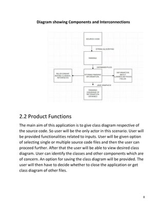


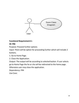

This document is a Software Requirements Specification (SRS) for a tool that converts Java source code into UML class diagrams, addressing the need for improved visualization and maintenance of object-oriented designs. It outlines the purpose, specific functionalities, operating environment, and constraints of the software, including user requirements and interaction scenarios. The project aims to provide a user-friendly interface and efficient algorithmic support for visualizing class relationships, benefiting both novice and professional Java developers.