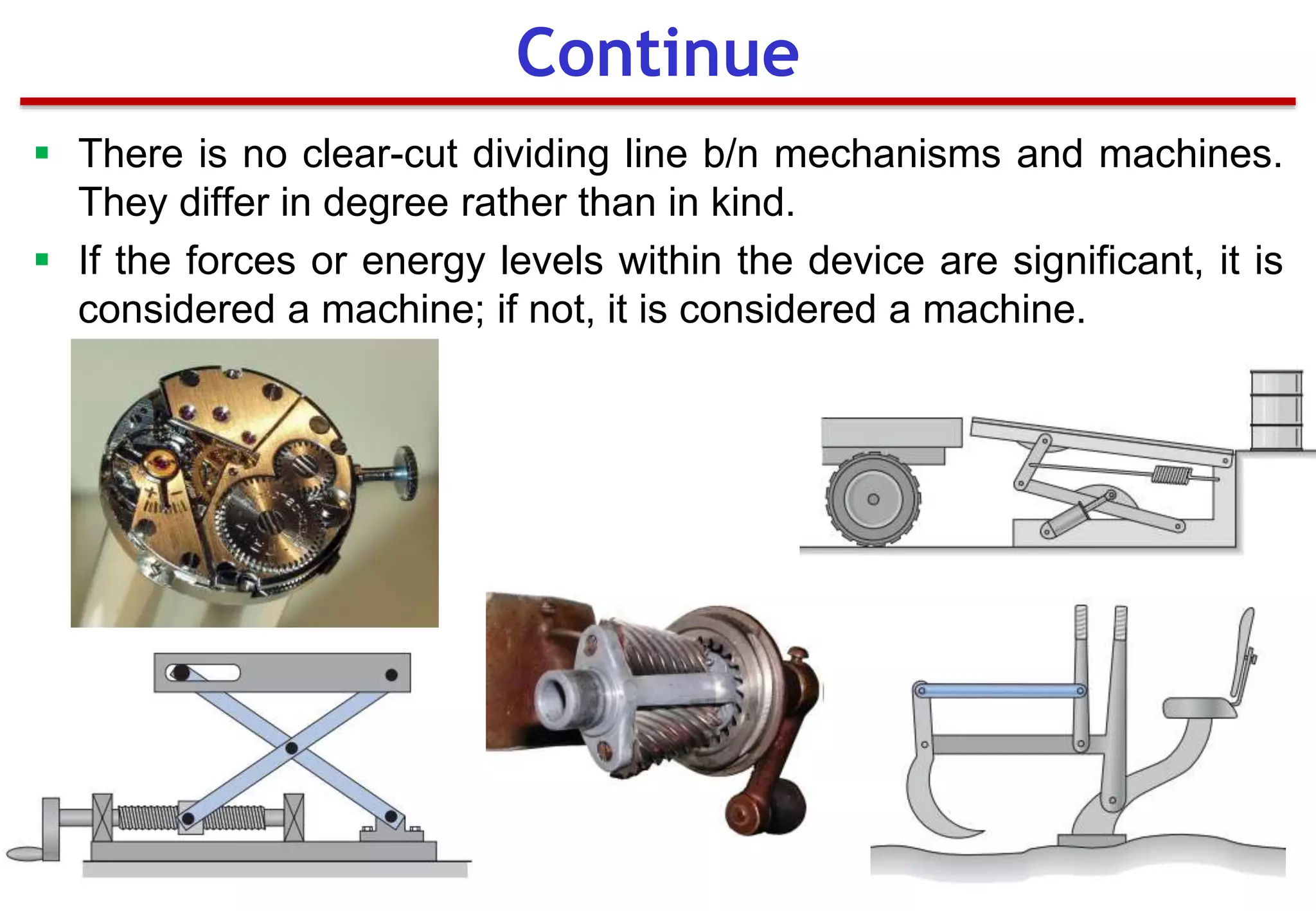
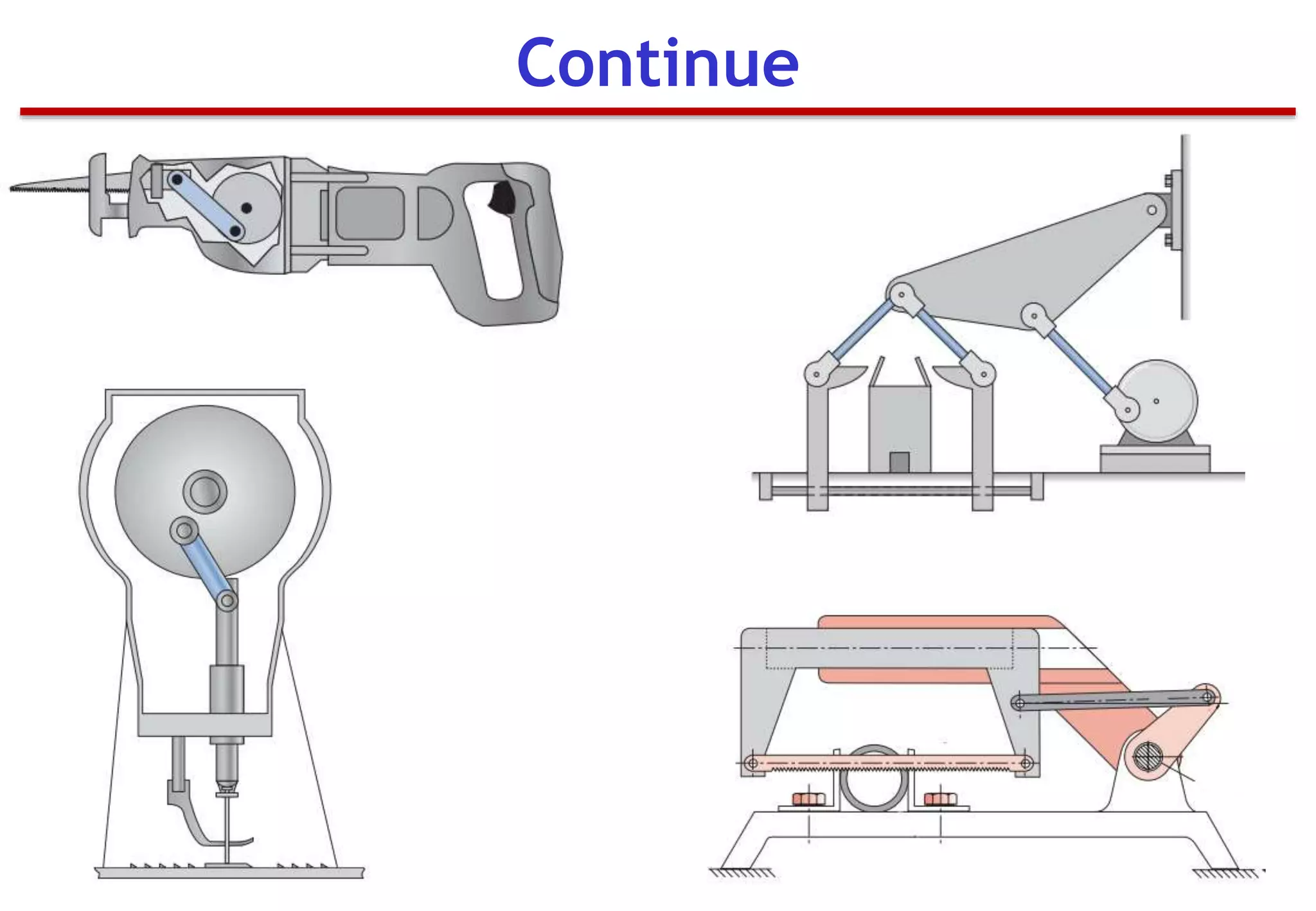
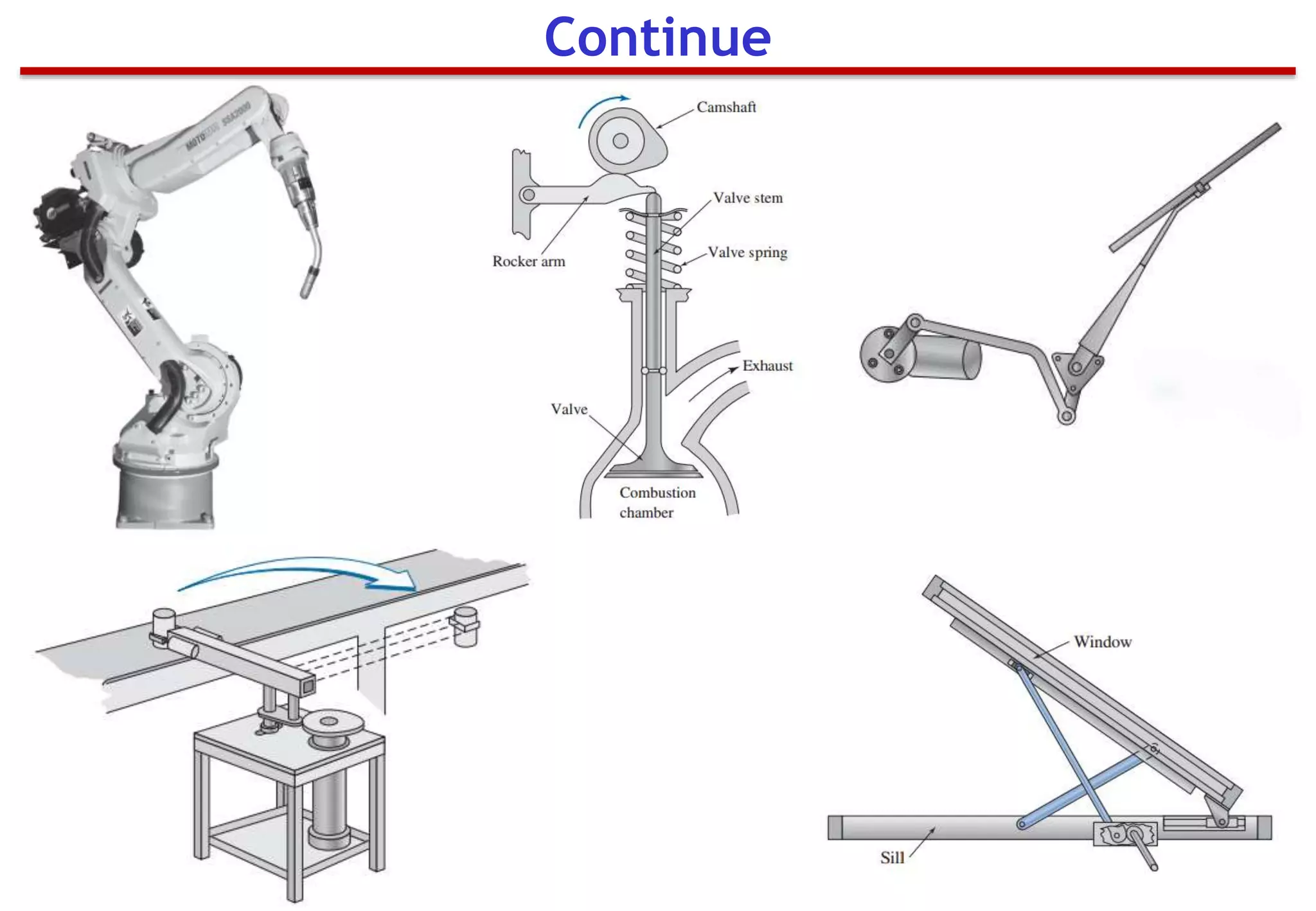
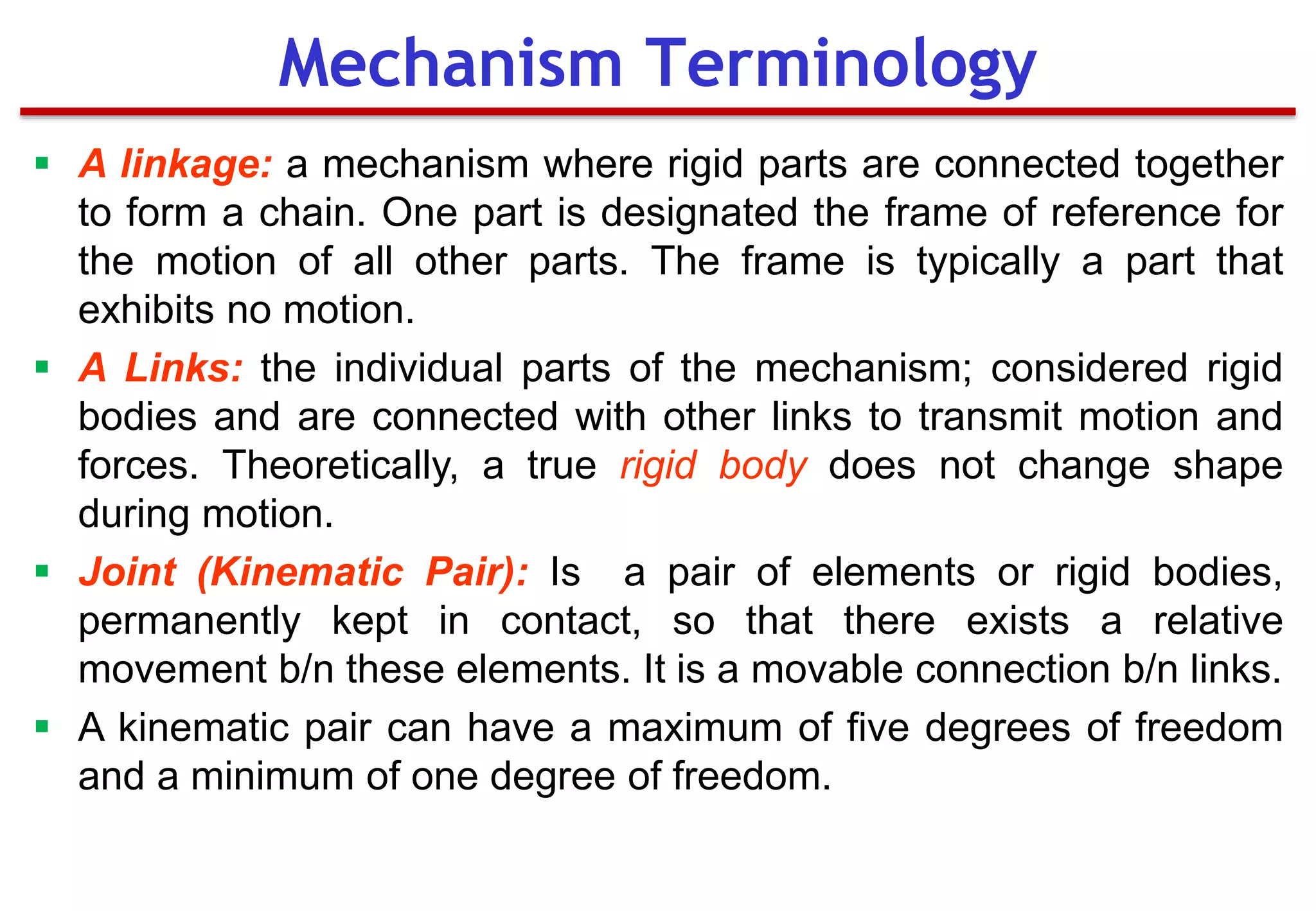
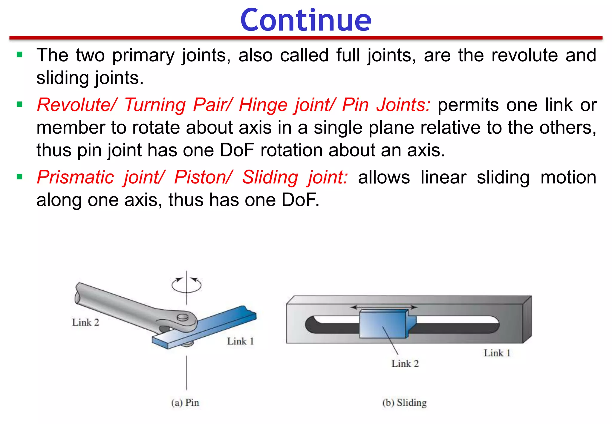
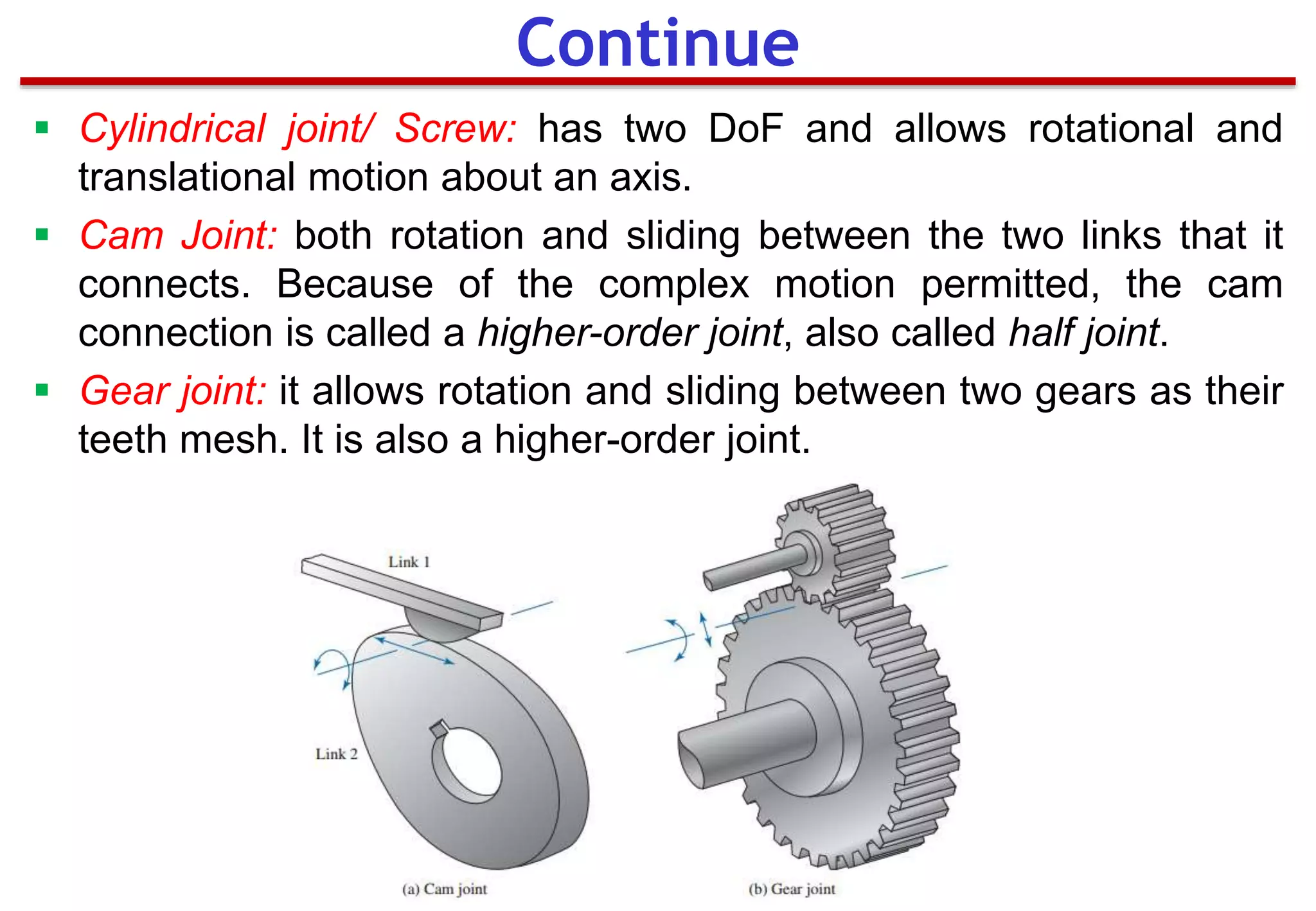
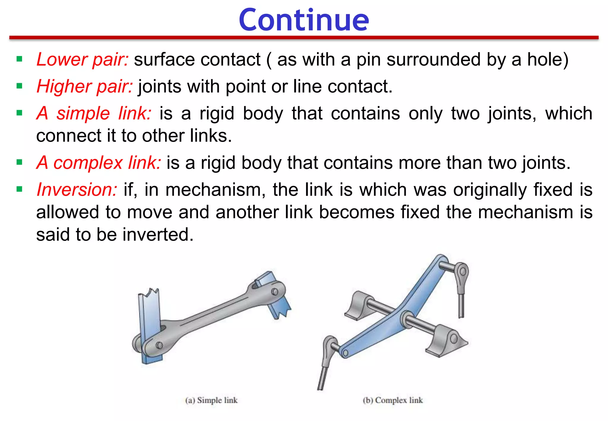
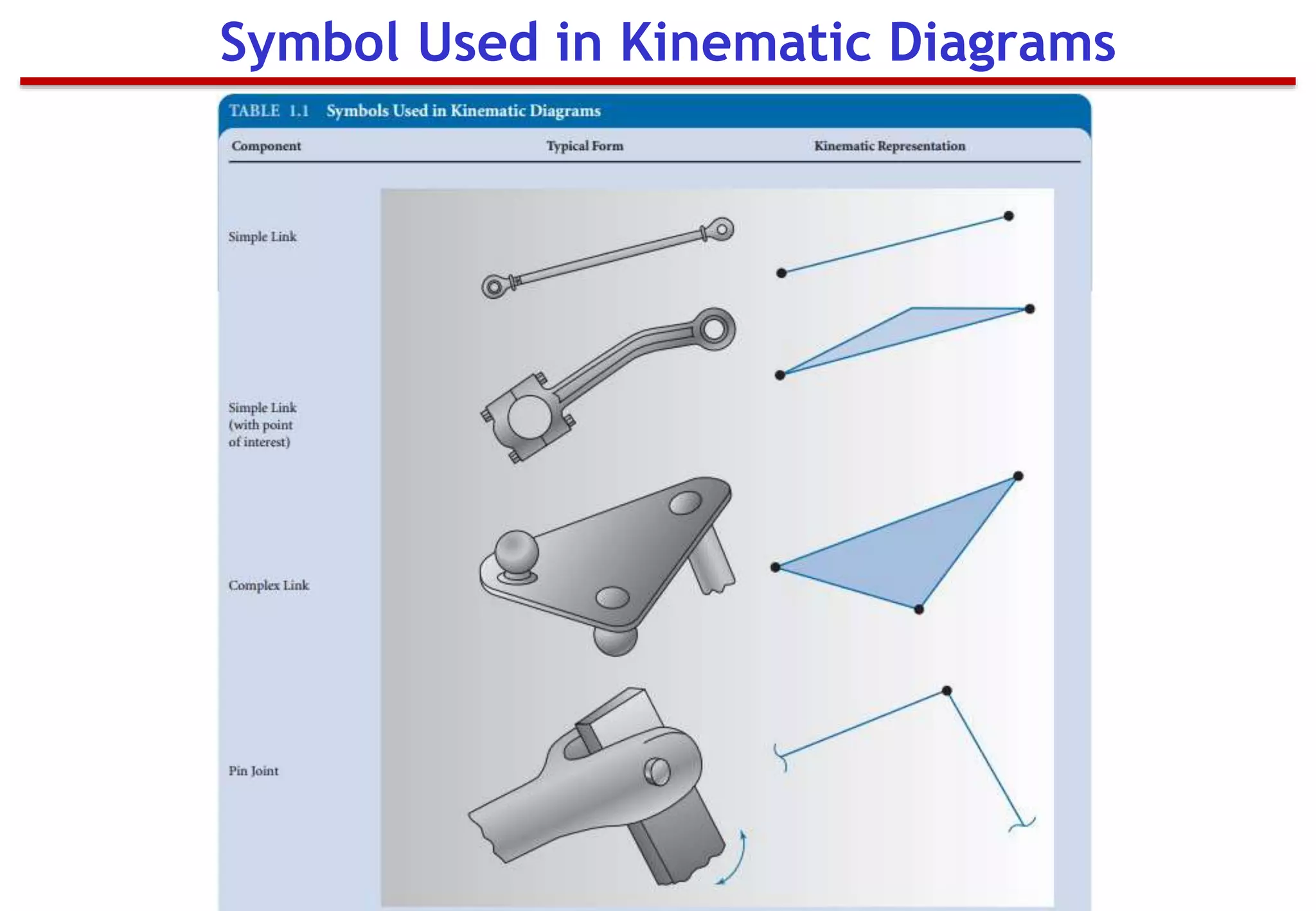
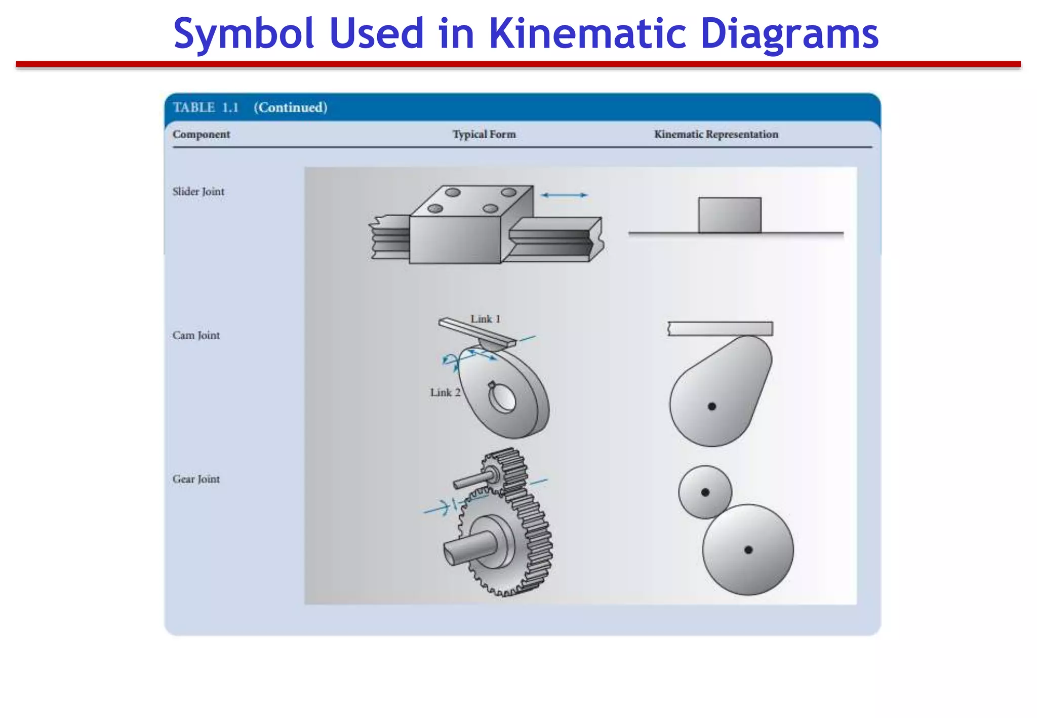
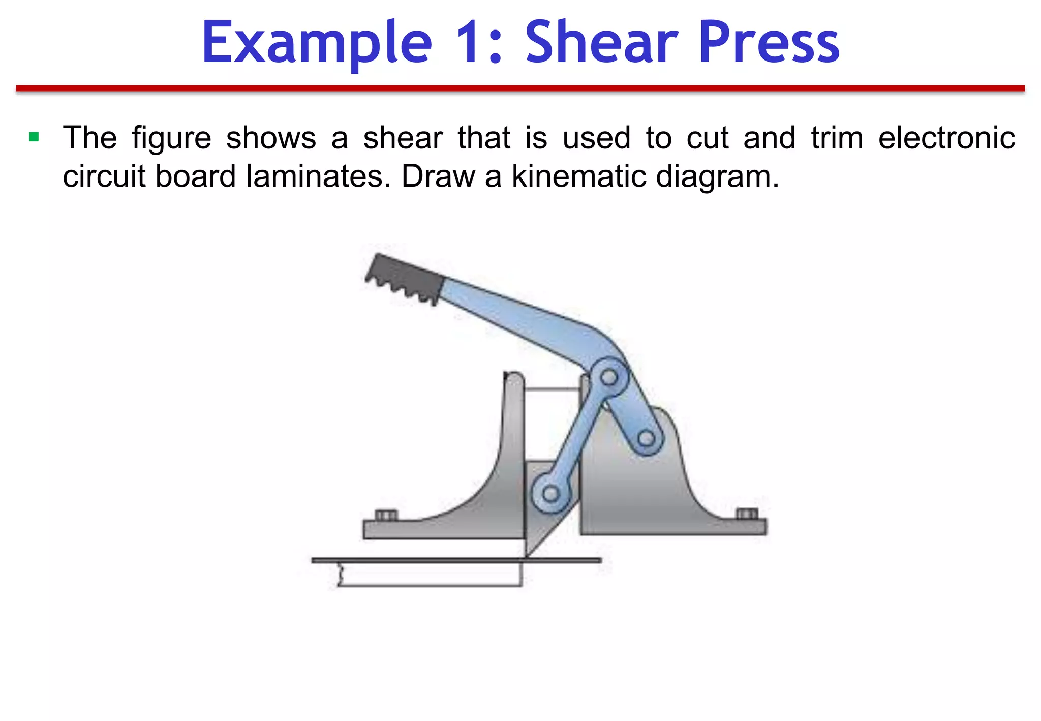
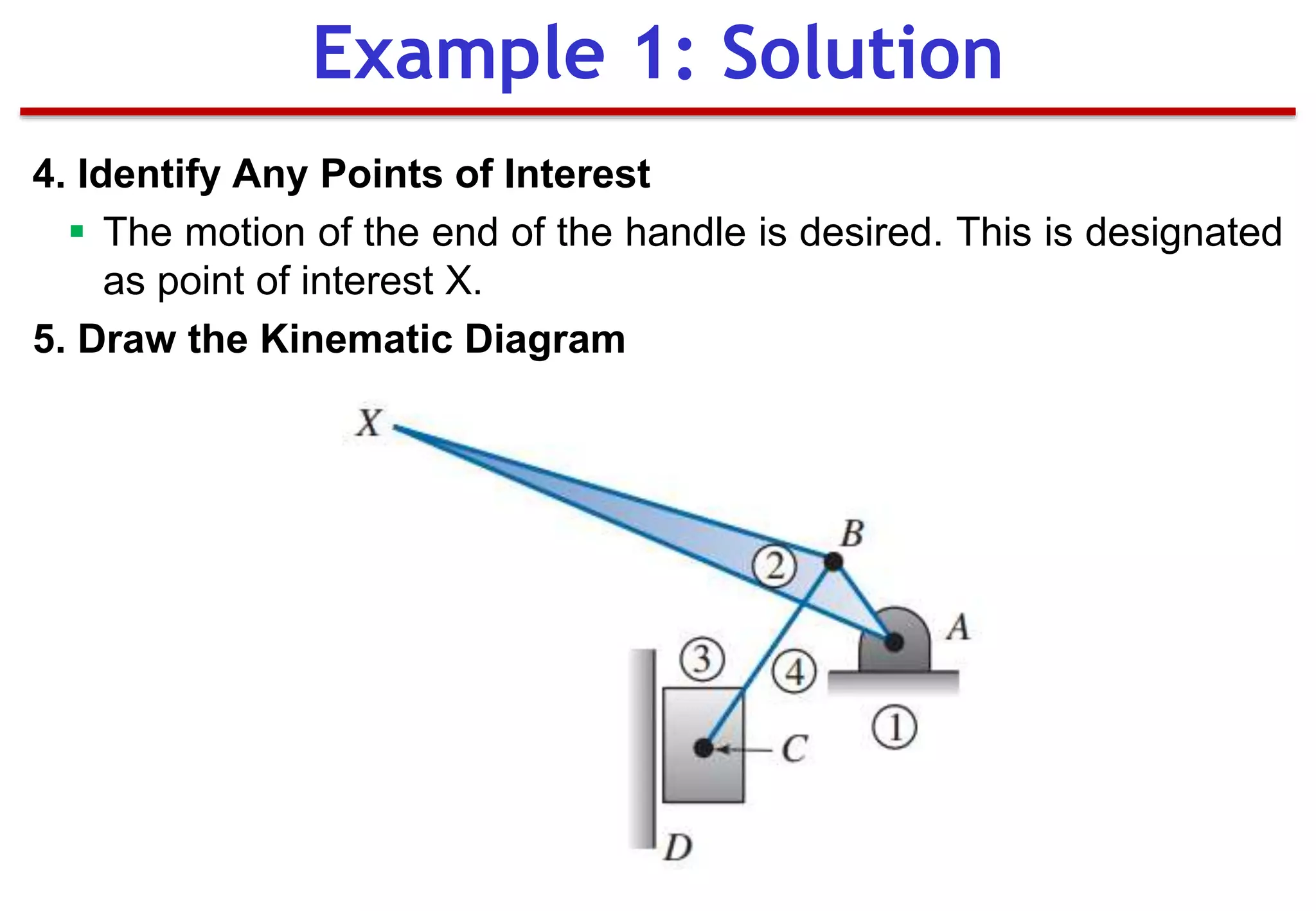
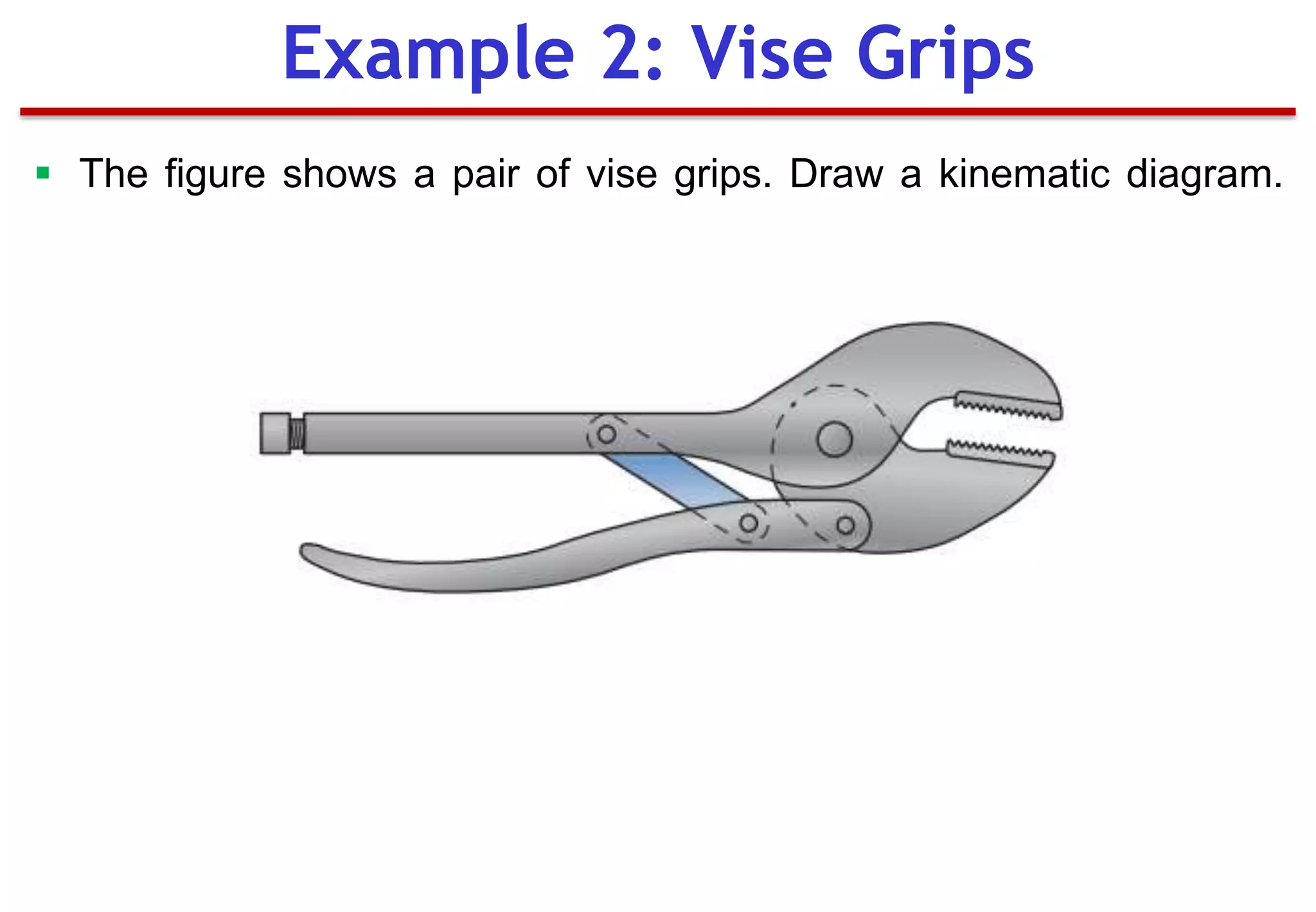
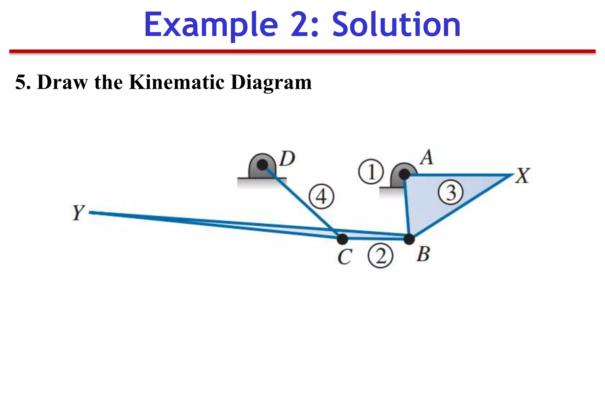
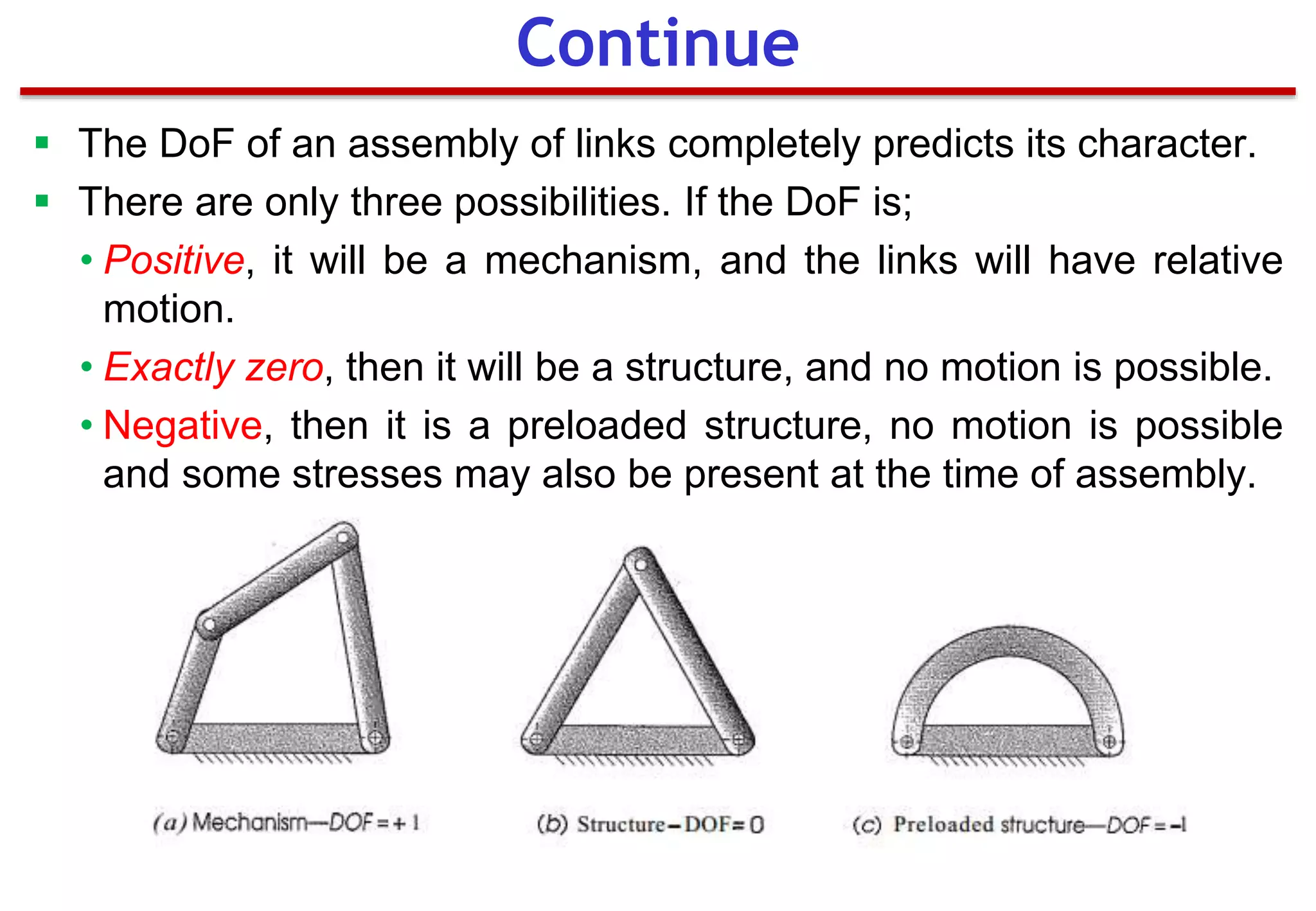
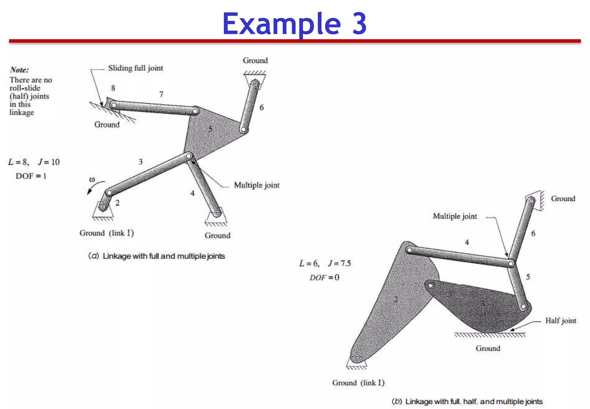
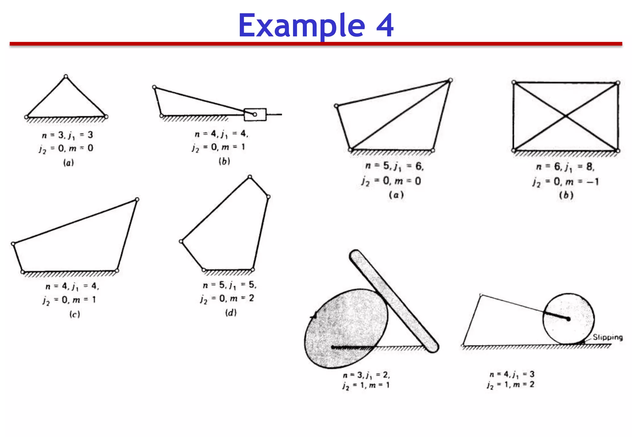
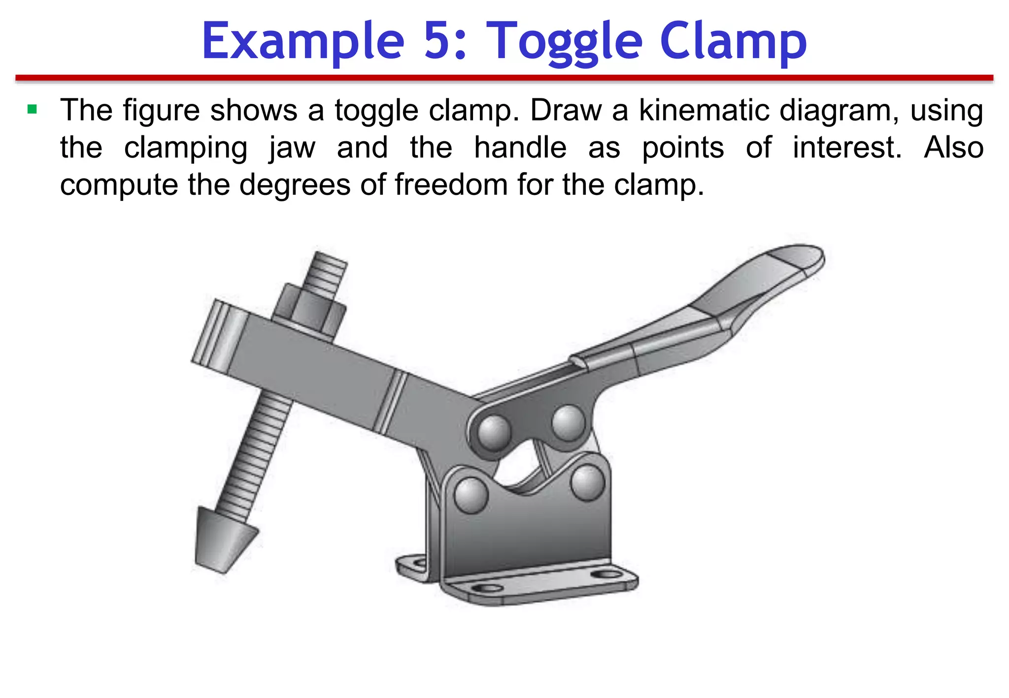
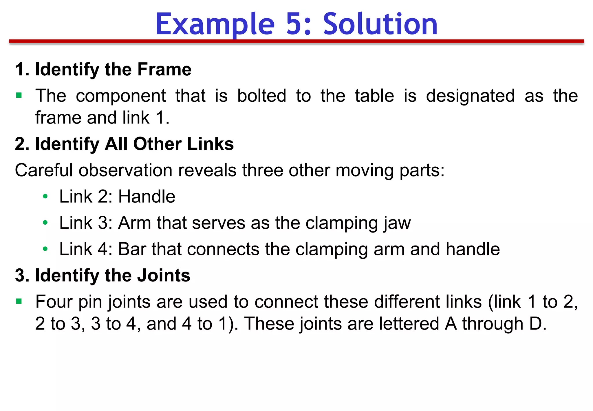
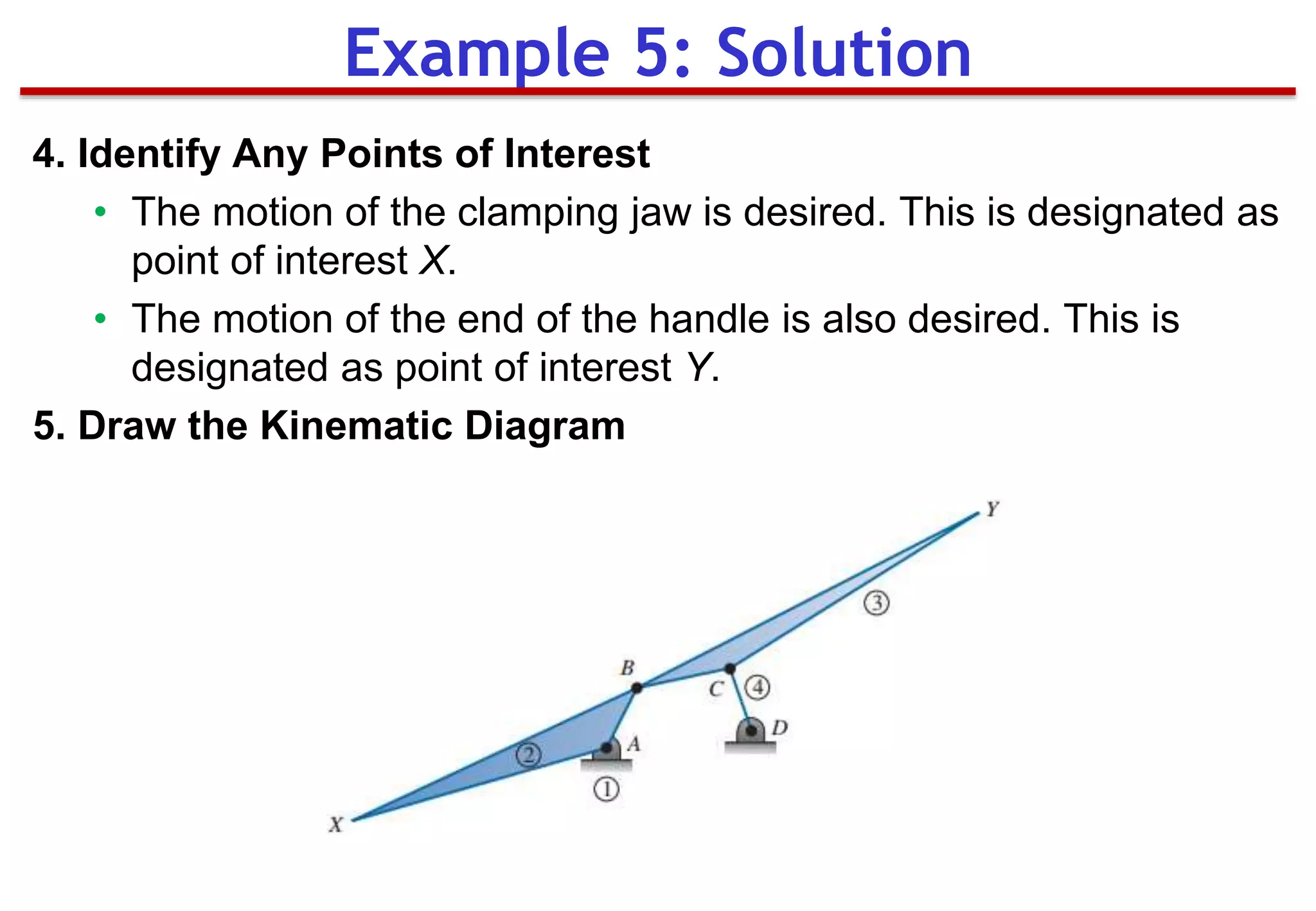
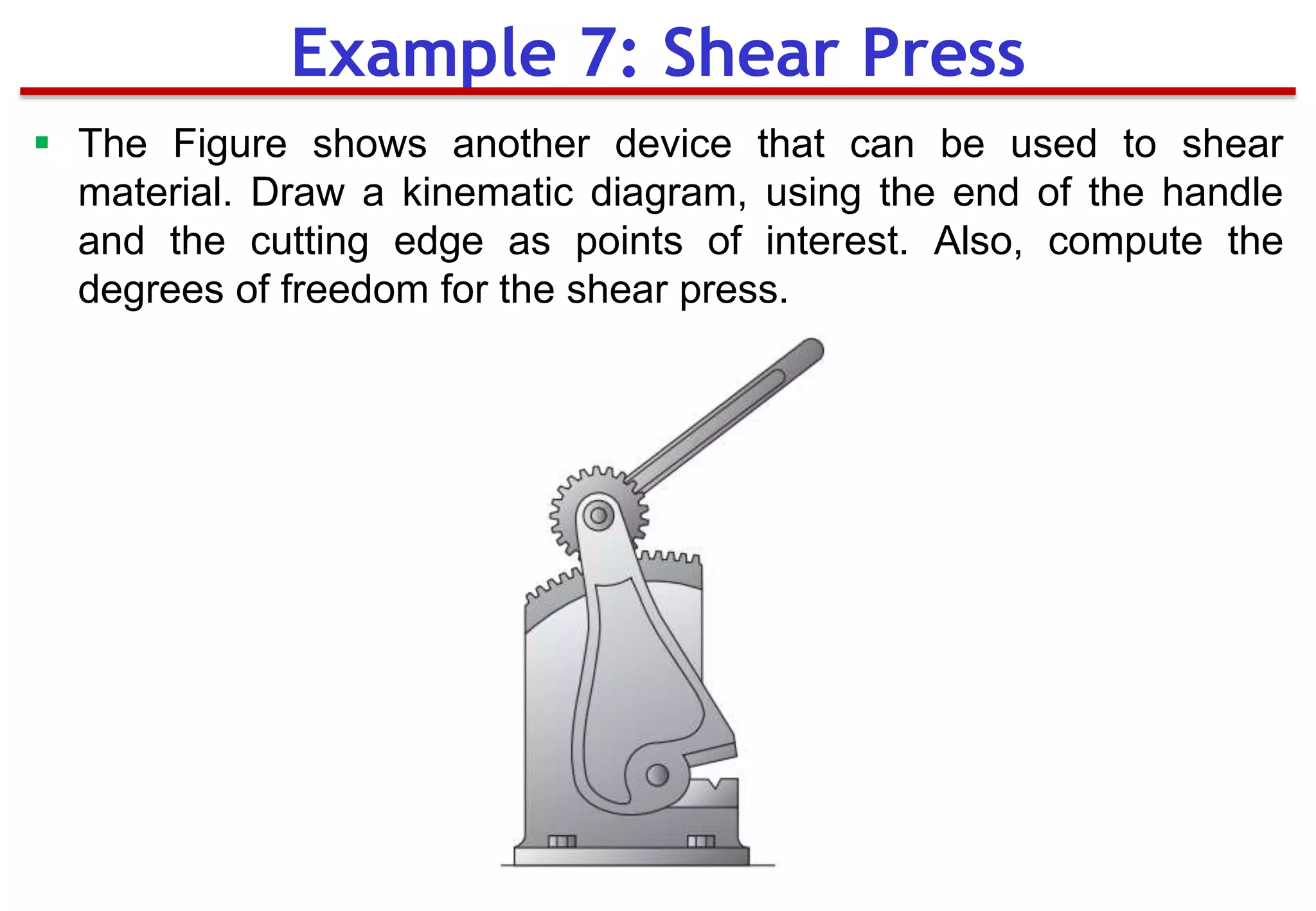
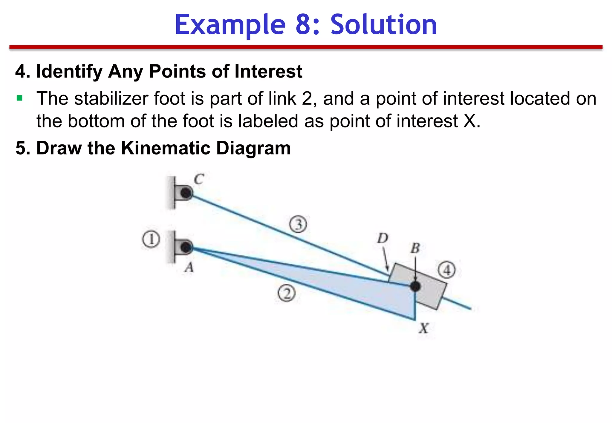
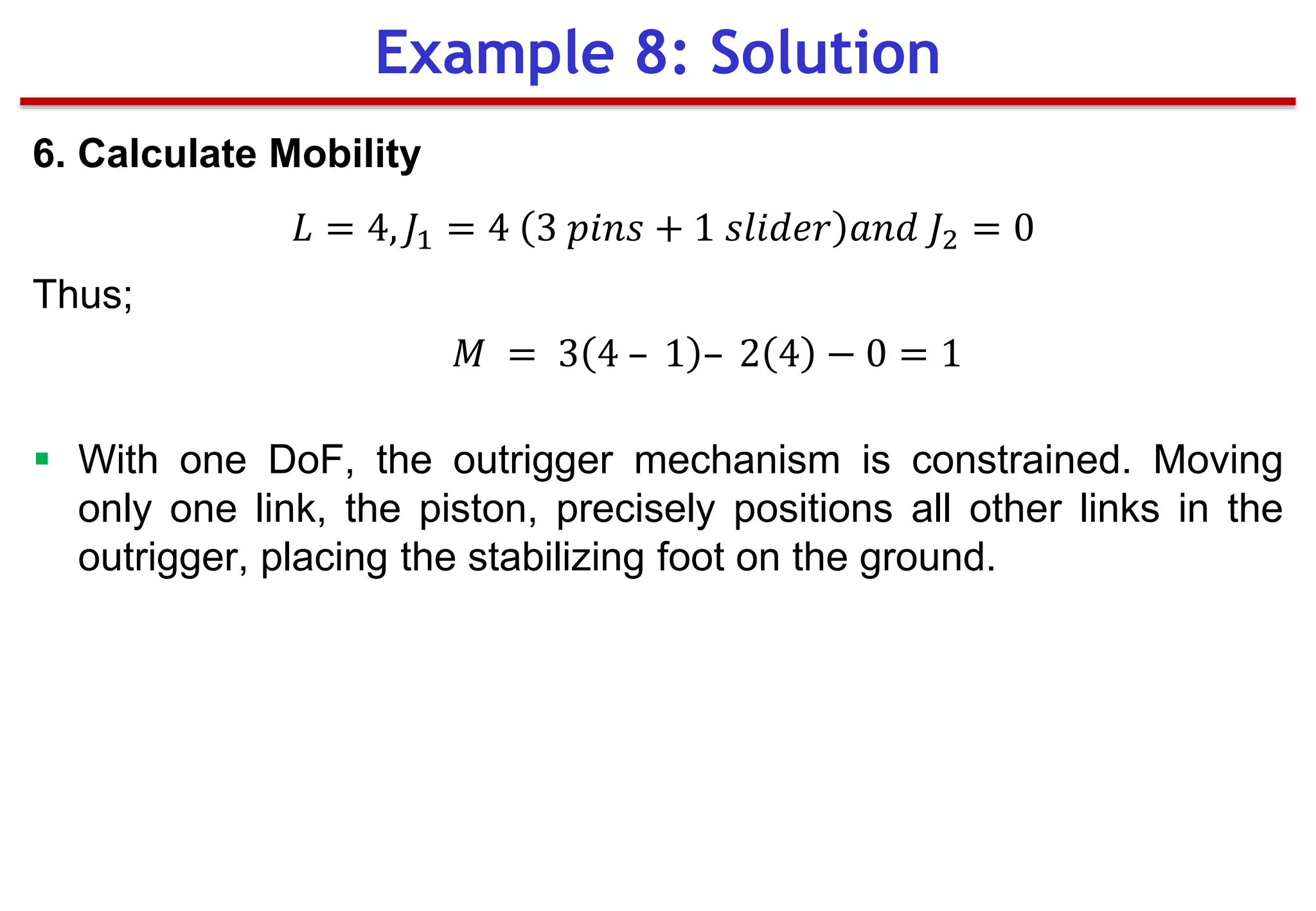
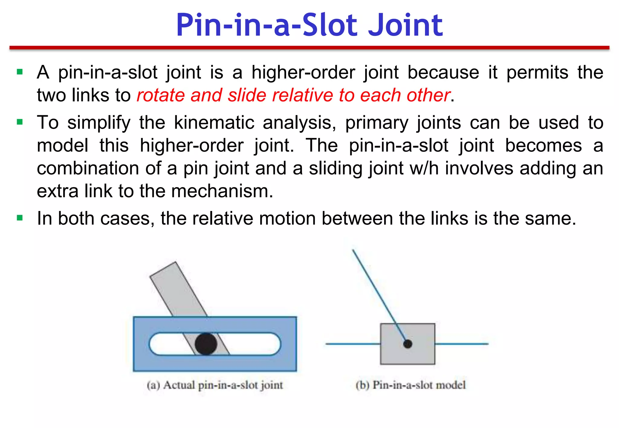
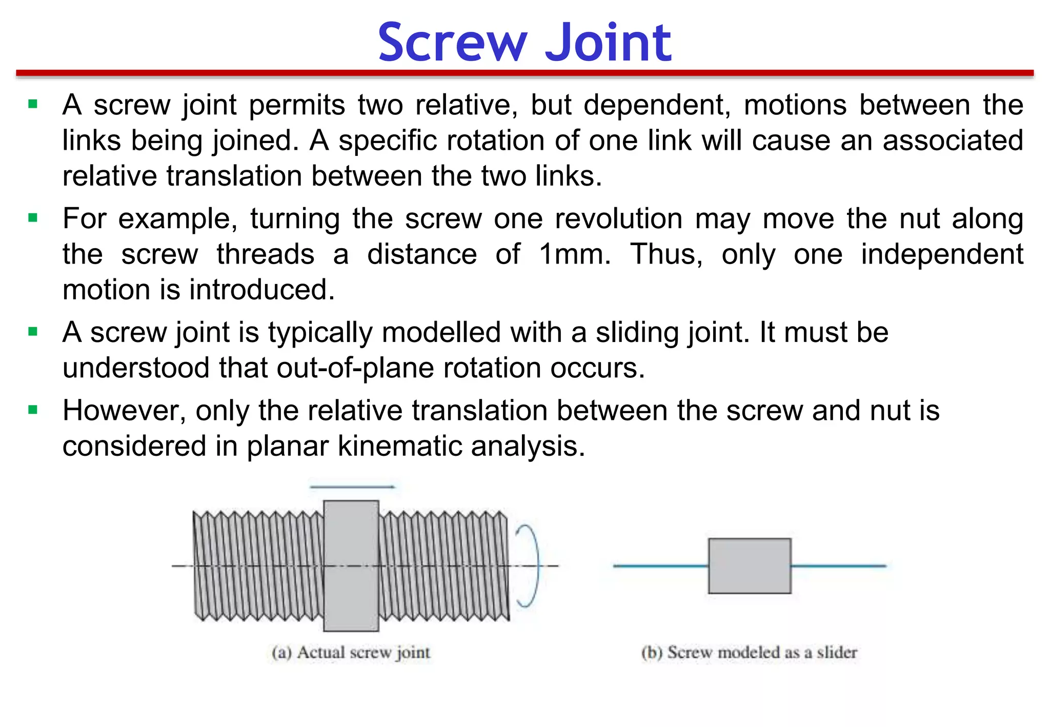
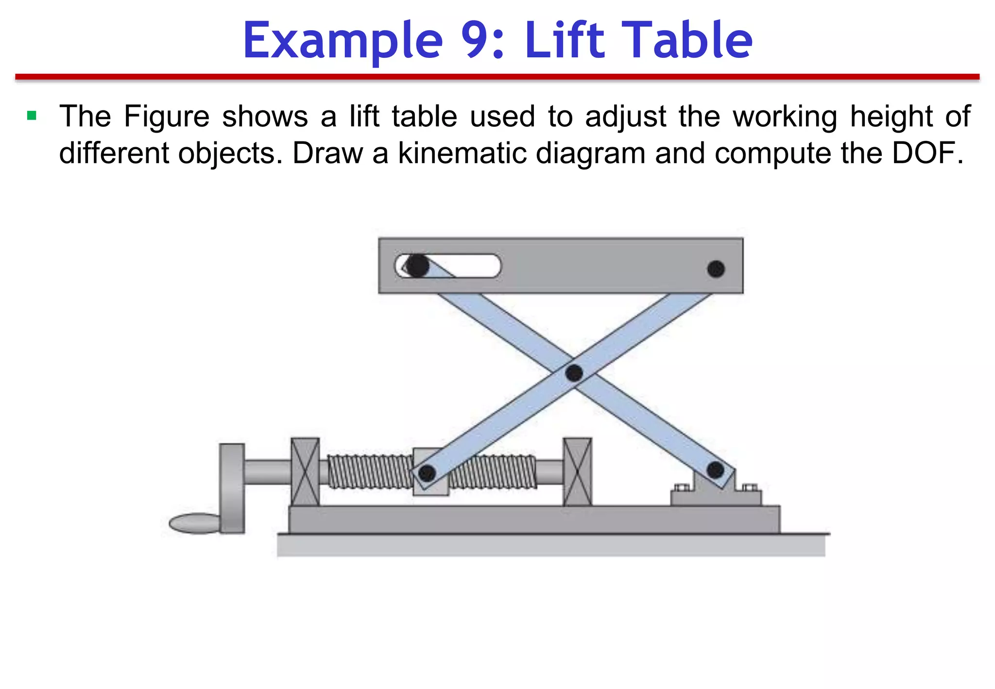
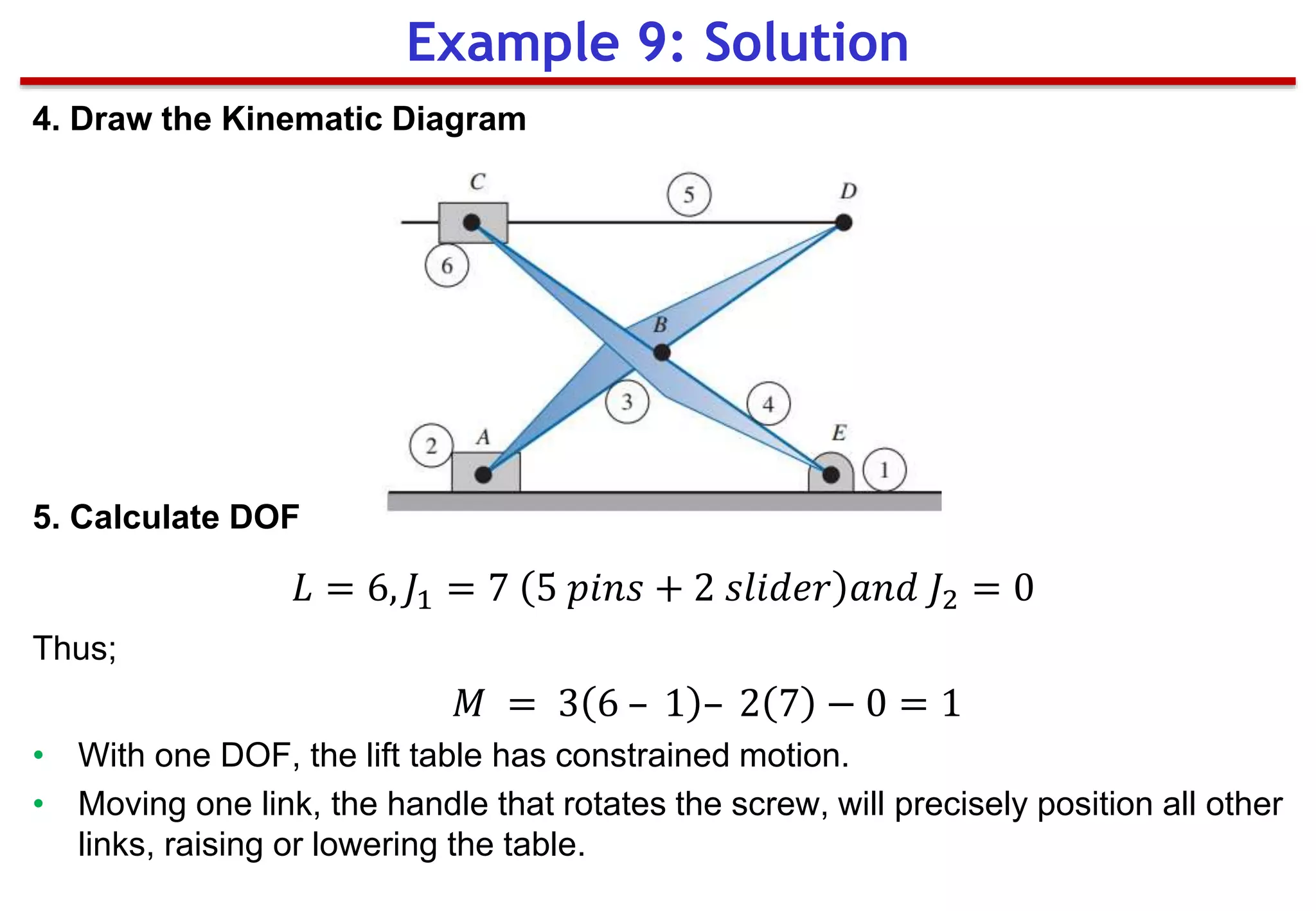
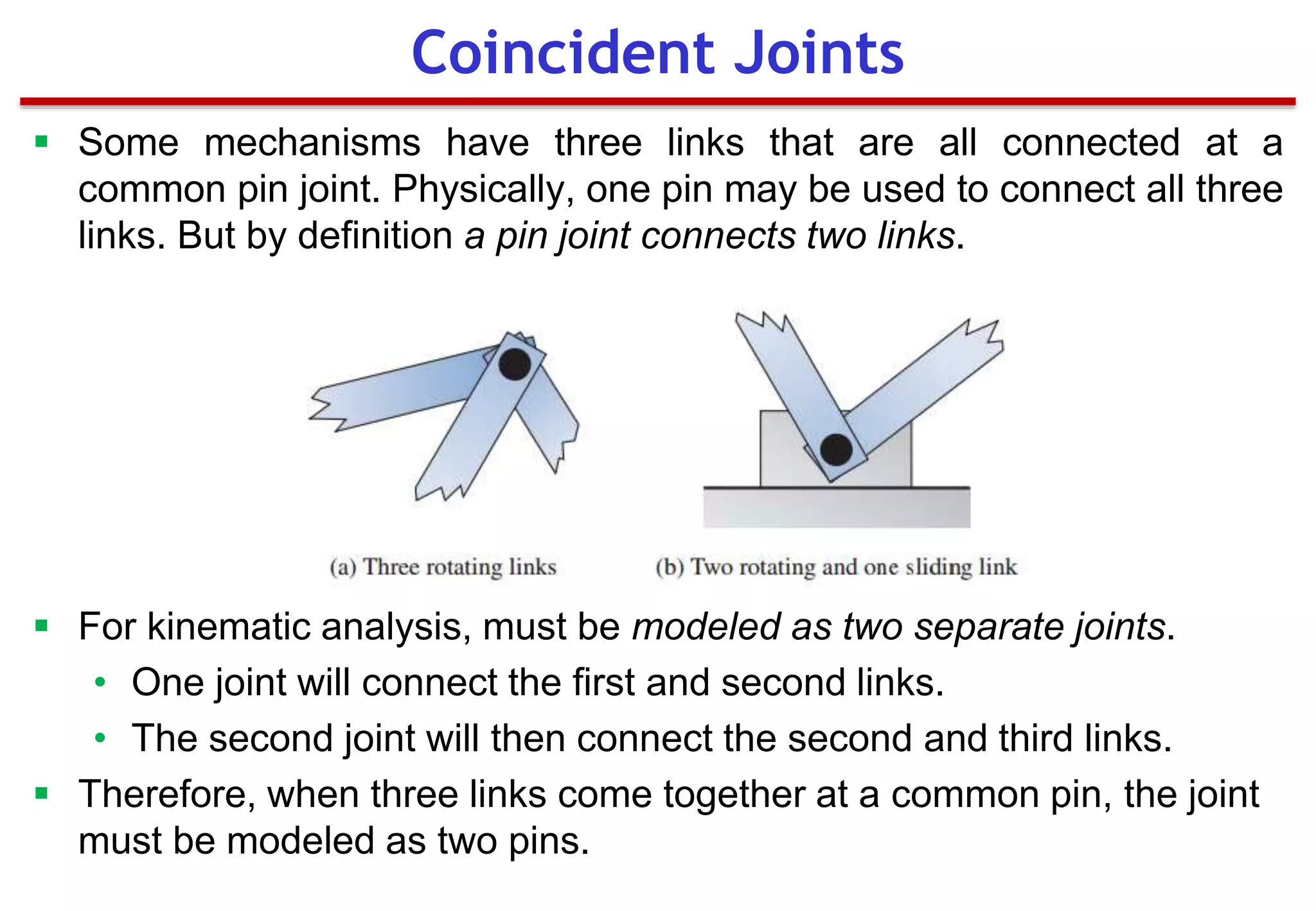
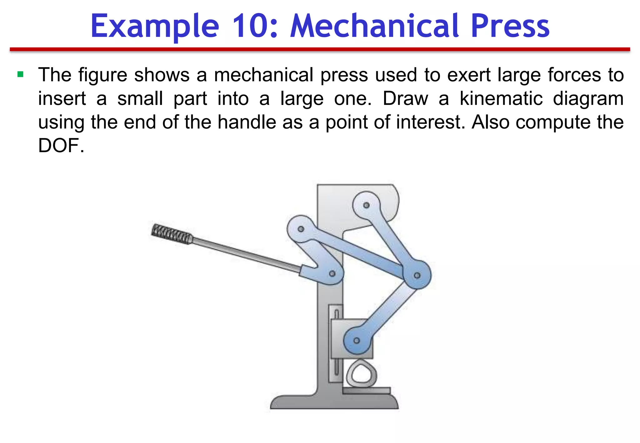
SlideShare a Scribd company logo
1 of 62
Mechanisms of Machinery
(MEng 3071)
Chapter 1
Introduction
University of Gondar
Institute of Technology
School of Mechanical & Industrial Engineering
Prepared by: Biniam T.
28 October 2018
Outline
▀ Introduction (Basics)
▀ Machines and Mechanisms
▀ Kinematics and Kinetics of
Mechanisms
▀ Mechanism Terminology
▀ Kinematic Diagrams
▀ Examples 1 & 2.
 Kinematic Inversion
 Mobility (Degree of Freedom)
▀ Examples 3 – 8.
Mechanisms of Machinery
 The theory of machines and mechanism is used to understand
the relationship b/n geometry and motions of the parts of a
machine, or mechanism, and the forces that produce these
motion.
 Kinematics: The study of motion without regard to forces.
 Kinetics: The study of forces on systems in motion.
 The initial problem in design analysis of mechanical systems is
determining the system’s motion, kinematics; primary focus of
this course.
 Secondary problem is power source selection to provide
sufficient force to operate the machine. The study of dynamic
forces is termed as kinetics.
Mechanism and Machine
 A mechanism is a device that transforms motion to some desirable
pattern and typically develops very low forces and transmits little
power.
 It can also defined as a system of elements arranged to transmit
motion in a predetermined fashion.
 Shortly, it is a means of transmitting, controlling, or constraining
relative movement. Some example of common mechanisms are a
pencil sharpener, a camera shutter, an analog clock, a folding chair
and an umbrella.
 A machine typically contains mechanisms that are designed to
provide significant forces and transmit power. It is used to alter,
transmit, and direct forces to accomplish a specific objective.
 Example: A chain saw machine that directs forces to the chain with
the objective of cutting wood.
Continue
 There is no clear-cut dividing line b/n mechanisms and machines.
They differ in degree rather than in kind.
 If the forces or energy levels within the device are significant, it is
considered a machine; if not, it is considered a machine.
Continue
Continue
Mechanism Terminology
 A linkage: a mechanism where rigid parts are connected together
to form a chain. One part is designated the frame of reference for
the motion of all other parts. The frame is typically a part that
exhibits no motion.
 A Links: the individual parts of the mechanism; considered rigid
bodies and are connected with other links to transmit motion and
forces. Theoretically, a true rigid body does not change shape
during motion.
 Joint (Kinematic Pair): Is a pair of elements or rigid bodies,
permanently kept in contact, so that there exists a relative
movement b/n these elements. It is a movable connection b/n links.
 A kinematic pair can have a maximum of five degrees of freedom
and a minimum of one degree of freedom.
Continue
 The two primary joints, also called full joints, are the revolute and
sliding joints.
 Revolute/ Turning Pair/ Hinge joint/ Pin Joints: permits one link or
member to rotate about axis in a single plane relative to the others,
thus pin joint has one DoF rotation about an axis.
 Prismatic joint/ Piston/ Sliding joint: allows linear sliding motion
along one axis, thus has one DoF.
Continue
 Cylindrical joint/ Screw: has two DoF and allows rotational and
translational motion about an axis.
 Cam Joint: both rotation and sliding between the two links that it
connects. Because of the complex motion permitted, the cam
connection is called a higher-order joint, also called half joint.
 Gear joint: it allows rotation and sliding between two gears as their
teeth mesh. It is also a higher-order joint.
Continue
 Lower pair: surface contact ( as with a pin surrounded by a hole)
 Higher pair: joints with point or line contact.
 A simple link: is a rigid body that contains only two joints, which
connect it to other links.
 A complex link: is a rigid body that contains more than two joints.
 Inversion: if, in mechanism, the link is which was originally fixed is
allowed to move and another link becomes fixed the mechanism is
said to be inverted.
Continue
 Form Closed: joint is kept together or closed by its geometry.
 Force closed: requires some external force to keep it together or
closed. This force could be supplied by gravity, a spring, or any
external means.
 Joint order: defined as the number of links joined minus one. It has
significance in the proper determination of overall DoF of assembly.
 A point of interest: is a point on a link where the motion is of special
interest. Once kinematic analysis is performed, the displacement,
velocity, and accelerations of that point are determined.
 An actuator: is the component that drives the mechanism.
Common actuators include motors (electric and hydraulic),
engines, cylinders (hydraulic and pneumatic), ball-screw motors,
and solenoids.
 Manually operated machines utilize human motion, such as turning
a crank, as the actuator.
 Motion can be thought of as a time series of displacement between
successive position of a point or a particle.
 Type of Motion:
• Rectilinear Motion: moves along a straight line
• Plane Motion: Confined to one plane, can be either rectilinear or
curvilinear.
• Helical Motion: when a body moves so that each point of the body
has motion of rotation about a fixed axis and at the same time has
translational parallel to the axis.
• Spherical Motion: when a body moves so that each point on the
body has motion about a fixed point and remains at a constant
distance from the fixed point.
• Spacial Motion: when the motion of a body is not confined to a
plane, the body is said to have Spacial motion. Helical and
spherical motion are special cases of Spacial motion.
Motion
 Coordinate are mathematical ways or models that describes the
position and motion of a dynamic system or a mechanism.
 Independent coordinate: these are the minimum number of
coordinates that describes the position of a system. The number of
independent is coordinates is equal to the DoF of the system.
 Dependent coordinate: these are number of coordinates (which are
not independent) interrelated through certain independent equation
known as constraint equations. The number dependent coordinate
larger than the DoF.
 For a system defined by using ‘n’ coordinates and having ‘m’
independent constraint equations, the number of DoF ‘f’ is given by
𝑓 = 𝑛 − 𝑚
Coordinate Systems
 In analyzing the motion of a machine, it is often difficult to visualize
the movement of the components in a full assembly drawing.
 A pictorial of an entire machine becomes complex; difficult to focus
on motion of mechanism under consideration.
 It is easier to represent the parts in skeleton form so that only the
dimensions that influence the motion of the mechanism are shown.
 These “stripped-down” sketches of mechanisms are often referred
to as kinematic diagrams.
 For convenient reference, the links are numbered, starting with the
frame as link number 1.
 To avoid confusion, the joints should be lettered.
 Drawn to a scale proportional to the actual mechanism.
Kinematic Diagrams
Symbol Used in Kinematic Diagrams
Example 1: Shear Press
 The figure shows a shear that is used to cut and trim electronic
circuit board laminates. Draw a kinematic diagram.
1. Identify the Frame
 1st Step: decide the part that will be designated as the frame. The
motion of all other links will be determined relative to the frame.
 In some cases, its selection is obvious as the frame is firmly
attached to the ground.
 In this problem, the large base that is bolted to the table is
designated as the frame.
 The motion of all other links is determined relative to the base.
The base is numbered as link 1.
Example 1: Solution
2. Identify All Other Links
Careful observation reveals three other moving parts:
 Link 2: Handle
 Link 3: Cutting blade
 Link 4: Bar that connects the cutter with the handle
3. Identify the Joints
 Pin joints are used to connect link 1 to 2, link 2 to 4, and link 3 to
4. These joints are lettered A through C.
 The cutter slides up and down, along the base. This sliding joint
connects link 4 to 1 (ground), and is lettered D.
Example 1: Solution
4. Identify Any Points of Interest
 The motion of the end of the handle is desired. This is designated
as point of interest X.
5. Draw the Kinematic Diagram
Example 1: Solution
Example 2: Vise Grips
 The figure shows a pair of vise grips. Draw a kinematic diagram.
1. Identify the Frame
 No parts are attached to the ground. The selection of the frame is
rather arbitrary.
 The top handle is designated as the frame. The motion of all
other links is determined relative to the top handle. The top
handle is numbered as link 1.
2. Identify All Other Links
Careful observation reveals three other moving parts:
 Link 2: Bottom handle
 Link 3: Bottom jaw
 Link 4: Bar that connects the top and bottom handle
Example 2: Solution
3. Identify the Joints
 Four pin joints are used to connect these different links (link 1 to
2, 2 to 3, 3 to 4, and 4 to 1).
 These joints are lettered A through D.
4. Identify Any Points of Interest
 The motion of the end of the bottom jaw is desired.
 This is designated as point of interest X.
 Finally, the motion of the end of the lower handle is also desired.
This is designated as point of interest Y.
Example 2: Solution
5. Draw the Kinematic Diagram
Example 2: Solution
 As seen in the previous examples, the first step in drawing a
kinematic diagram is selecting a member to serve as the frame.
 In some cases, the selection of a frame is arbitrary, as in the vise
grips from Example 2.
 As different links are chosen as a frame, the relative motion of the
links is not altered, but the absolute motion can be drastically
different.
 In Example 2, an important result of kinematic analysis is the
distance that the handle must be moved in order to open the jaw.
 This is a question of relative position of the links: the handle and
jaw. Because the relative motion of the links does not change with
the selection of a frame, the choice of a frame link is often not
important.
 Utilizing alternate links to serve as the fixed link is termed kinematic
inversion.
Kinematic Inversion
 The number of input parameters (usually pair variables) that must
be controlled independently to bring the device into a particular
position or orientation.
 The number of independent inputs required to precisely position all
links of the mechanism with respect to the ground.
 It can also be defined as the number of actuators needed to
operate the mechanism.
 A mechanism actuator could be manually moving one link to
another position, connecting a motor to the shaft of one link, or
pushing a piston of a hydraulic cylinder.
 Mechanisms with one DOF are termed Constrained Mechanisms.
 Most commercially produced mechanisms have 1 DOF.
 In contrast, robotic arms can have >= DOF.
Degree of Freedom
(Mobility)
 The DoF of an assembly of links completely predicts its character.
 There are only three possibilities. If the DoF is;
• Positive, it will be a mechanism, and the links will have relative
motion.
• Exactly zero, then it will be a structure, and no motion is possible.
• Negative, then it is a preloaded structure, no motion is possible
and some stresses may also be present at the time of assembly.
Continue
Generally;
 If DOF <= 0: Locked mechanisms.
• These mechanisms are unable to move and form a structure.
E.g. a truss: structure composed of simple links connected with
pin joints (zero DOF).
 DOF > 1: Unconstrained mechanisms.
• Need more than one driver to precisely operate them.
 To determine the overall DoF of any mechanisms, we must
account for the number of links and joints.
Continue
 DOF for planar linkages joined with common joints can be calculated
through Gruebler’s equation:
𝑀 = 3𝐿– 2𝐽 – 3𝐺
Where;
• M= degree of freedom or mobility
• L = total number of links in the mechanism
• 𝐽 = total number joints
• 𝐺 = number of grounded links
 In mechanism, even if more than one link is grounded, the net effect will
be to create one larger, higher-order ground link.
 The G always one, and the equation becomes:
𝑀 = 3 𝐿– 1 − 2𝐽
 The value of 𝐽 in the above equations must reflect the value of all joints in
the mechanism. That is, half joint count as 0.5 and full joint as 1.
Gruebler’s Equation
 It is the modification of Gruebler’s equation.
𝑀 = 3 𝐿 – 1 – 2𝐽1 – 𝐽2
Where;
• L = total number of links in the mechanism
• 𝐽1 = total number of full joints (pins or sliding joints)
• 𝐽2 = total number of half joints (cam or gear joints)
 The value of 𝐽1 and 𝐽2 must be carefully determined to account for
all full, half, and multiple joints in any linkage.
 Multiple joints count as one less than the number of links joined at
that joint and add to the ‘’full’’ (𝐽1) category.
Kutzbach’s Equation
Example 3
Example 4
Example 5: Toggle Clamp
 The figure shows a toggle clamp. Draw a kinematic diagram, using
the clamping jaw and the handle as points of interest. Also
compute the degrees of freedom for the clamp.
1. Identify the Frame
 The component that is bolted to the table is designated as the
frame and link 1.
2. Identify All Other Links
Careful observation reveals three other moving parts:
• Link 2: Handle
• Link 3: Arm that serves as the clamping jaw
• Link 4: Bar that connects the clamping arm and handle
3. Identify the Joints
 Four pin joints are used to connect these different links (link 1 to 2,
2 to 3, 3 to 4, and 4 to 1). These joints are lettered A through D.
Example 5: Solution
4. Identify Any Points of Interest
• The motion of the clamping jaw is desired. This is designated as
point of interest X.
• The motion of the end of the handle is also desired. This is
designated as point of interest Y.
5. Draw the Kinematic Diagram
Example 5: Solution
6. Calculate Mobility
 Having four links and four pin joints,
𝐿 = 4, 𝐽1 = 4 𝑎𝑛𝑑 𝐽2 = 0
Thus;
𝑀 = 3 4 – 1 – 2 4 − 0 = 1
 With one degree of freedom, the clamp mechanism is constrained.
Moving only one link, the handle, precisely positions all other links
in the clamp.
Example 5: Solution
Example 6: Can Crusher
 The Figure shows a beverage can crusher used to reduce the size
of cans for easier storage prior to recycling. Draw a kinematic
diagram, using the end of the handle as a point of interest. Also
compute the degrees of freedom for the device.
1. Identify the Frame
 The back portion of the device serves as a base/can be attached to a
wall. This component is designated as the frame; link 1.
2. Identify All Other Links
Careful observation shows three other moving parts:
• Link 2: Handle
• Link 3: Block that serves as the crushing surface
• Link 4: Bar that connects the crushing block and handle
3. Identify the Joints
 One pin joint connects the handle to the base; labeled as A.
 A second pin is used to connect link 4 to the handle; labeled B.
 The third pin connects the crushing block and link 4; labeled C.
 The crushing block slides vertically during operation; therefore, a
sliding joint connects the crushing block to the base; labeled D.
Example 6: Solution
4. Identify Any Points of Interest
 The motion of the handle end is desired; point of interest X.
5. Draw the Kinematic Diagram
Example 6: Solution
6. Calculate mobility
𝐿 = 4, 𝐽1 = 4 (3 𝑝𝑖𝑛𝑠 + 1 𝑠𝑙𝑖𝑑𝑒𝑟) 𝑎𝑛𝑑 𝐽2 = 0
Thus;
𝑀 = 3 4 – 1 – 2 4 − 0 = 1
 With one degree of freedom, the can crusher mechanism is
constrained. Moving only one link, the handle, precisely positions
all other links and crushes a beverage can placed under the
crushing block.
Example 6: Solution
Example 7: Shear Press
 The Figure shows another device that can be used to shear
material. Draw a kinematic diagram, using the end of the handle
and the cutting edge as points of interest. Also, compute the
degrees of freedom for the shear press.
1. Identify the Frame
 The base is bolted to a working surface and can be designated as the
frame. The frame is numbered as link 1.
2. Identify All Other Links
Careful observation reveals two other moving parts:
• Link 2: Gear/handle
• Link 3: Cutting lever
3. Identify the Joints
 Two pin joints are used to connect these different parts.
• One pin connects the cutting lever to the frame; labeled as A.
• A second pin is used to connect the gear/handle to the cutting
lever. It is labeled B.
• The gear/handle is also connected to the frame with a gear joint.
This higher-order joint is labeled C.
Example 7: Solution
4. Identify Any Points of Interest
 The motion of the handle end is desired and is designated as point
of interest X. The motion of the cutting surface is also desired and
is designated as point of interest Y.
5. Draw the Kinematic Diagram
Example 7: Solution
6. Calculate Mobility
𝐿 = 3, 𝐽1 = 2 𝑎𝑛𝑑 𝐽2 = 1 (𝑔𝑒𝑎𝑟 𝑐𝑜𝑛𝑛𝑒𝑐𝑡𝑖𝑜𝑛)
Thus;
𝑀 = 3 3 – 1 – 2 2 − 1 = 1
 With one degree of freedom, the shear press mechanism is
constrained. Moving only one link, the handle, precisely positions
all other links and brings the cutting edge onto the work piece.
Example 7: Solution
 In order to operate a mechanism, an actuator/driver device, is
required to provide the input motion and energy.
 Common components used to drive a mechanism with a limited
linear stroke include Hydraulic Cylinders.
 The cylinder unit contains a rod and piston assembly that slides
relative to a cylinder. For kinematic purposes, these are two links
(piston/rod and cylinder), connected with a sliding joint.
 The cylinder and rod end usually have provisions for pin joints.
Actuators and Drivers
 The Figure shows an outrigger foot to stabilize a utility truck. Draw
a kinematic diagram, using the bottom of the stabilizing foot as a
point of interest. Also compute the DOF.
Example 8
1. Identify the Frame
 The truck is designated as the frame, link 1. The motion of all other links is
determined relative to the truck.
2. Identify All Other Links
Careful observation reveals three other moving parts:
• Link 2: Outrigger leg
• Link 3: Cylinder
• Link 4: Piston/rod
3. Identify the Joints
 Three pin joints are used to connect these different parts.
• One connects the outrigger leg with the truck frame; labeled as joint A.
• One connects the outrigger leg with the cylinder rod; labeled as joint B.
• One pin joint connects the cylinder to the truck frame; labeled as joint C.
• One sliding joint is present in the cylinder unit. This connects the
piston/rod with the cylinder. It is labeled as joint D.
Example 8: Solution
4. Identify Any Points of Interest
 The stabilizer foot is part of link 2, and a point of interest located on
the bottom of the foot is labeled as point of interest X.
5. Draw the Kinematic Diagram
Example 8: Solution
6. Calculate Mobility
𝐿 = 4, 𝐽1 = 4 3 𝑝𝑖𝑛𝑠 + 1 𝑠𝑙𝑖𝑑𝑒𝑟 𝑎𝑛𝑑 𝐽2 = 0
Thus;
𝑀 = 3 4 – 1 – 2 4 − 0 = 1
 With one DoF, the outrigger mechanism is constrained. Moving
only one link, the piston, precisely positions all other links in the
outrigger, placing the stabilizing foot on the ground.
Example 8: Solution
 A pin-in-a-slot joint is a higher-order joint because it permits the
two links to rotate and slide relative to each other.
 To simplify the kinematic analysis, primary joints can be used to
model this higher-order joint. The pin-in-a-slot joint becomes a
combination of a pin joint and a sliding joint w/h involves adding an
extra link to the mechanism.
 In both cases, the relative motion between the links is the same.
Pin-in-a-Slot Joint
 A screw joint permits two relative, but dependent, motions between the
links being joined. A specific rotation of one link will cause an associated
relative translation between the two links.
 For example, turning the screw one revolution may move the nut along
the screw threads a distance of 1mm. Thus, only one independent
motion is introduced.
 A screw joint is typically modelled with a sliding joint. It must be
understood that out-of-plane rotation occurs.
 However, only the relative translation between the screw and nut is
considered in planar kinematic analysis.
Screw Joint
 The Figure shows a lift table used to adjust the working height of
different objects. Draw a kinematic diagram and compute the DOF.
Example 9: Lift Table
1. Identify the Frame
 The bottom base plate rests on a fixed surface (frame). The bearing at the
bottom right is bolted to the base plate.
 Likewise, the two bearings that support the screw on the left are bolted to the
base plate.
 Only the relative translation of the nut will be included in the kinematic model.
 The screw will also be considered as part of the frame w/h will be numbered as
link 1.
2. Identify All Other Links
Careful observation reveals five other moving parts:
• Link 2: Nut
• Link 3: Support arm that ties the nut to the table
• Link 4: Support arm that ties the fixed bearing to the slot in the table
• Link 5: Table
• Link 6: Extra link used to model the pin in slot joint with separate pin and
slider joints
Example 9: Solution
3. Identify the Joints
• A sliding joint is used to model the motion between the screw and
the nut.
• Pin joint (A) connects the nut to the support arm (link 3).
• Pin joint (B) connects the two support arms: link 3 and link 4.
• Pin joint (C) connects link 3 to link 6.
• A sliding joint joins link 6 to the table, link 5.
• Pin joint (D) connects the table to the support arm, link 3.
• Pin joint (E) connects the base to the support arm (link 4).
Example 9: Solution
4. Draw the Kinematic Diagram
5. Calculate DOF
𝐿 = 6, 𝐽1 = 7 5 𝑝𝑖𝑛𝑠 + 2 𝑠𝑙𝑖𝑑𝑒𝑟 𝑎𝑛𝑑 𝐽2 = 0
Thus;
𝑀 = 3 6 – 1 – 2 7 − 0 = 1
• With one DOF, the lift table has constrained motion.
• Moving one link, the handle that rotates the screw, will precisely position all other
links, raising or lowering the table.
Example 9: Solution
 Some mechanisms have three links that are all connected at a
common pin joint. Physically, one pin may be used to connect all three
links. But by definition a pin joint connects two links.
 For kinematic analysis, must be modeled as two separate joints.
• One joint will connect the first and second links.
• The second joint will then connect the second and third links.
 Therefore, when three links come together at a common pin, the joint
must be modeled as two pins.
Coincident Joints
 The figure shows a mechanical press used to exert large forces to
insert a small part into a large one. Draw a kinematic diagram
using the end of the handle as a point of interest. Also compute the
DOF.
Example 10: Mechanical Press
1. Identify the Frame
• The bottom base for the mechanical press sits on a workbench and
remains stationary during operation. Therefore, this bottom base is
designated as the frame.
• The motion of all other links is determined relative to the bottom base.
The frame is numbered as link 1.
2. Identify All Other Links
Careful observation reveals five other moving parts:
– Link 2: Handle
– Link 3: Arm that connects the handle to the other arms
– Link 4: Arm that connects the base to the other arms
– Link 5: Press head
– Link 6: Arm that connects the head to the other arms
Example 10: Solution
3. Identify the Joints
– One pin connects the handle to the base labeled as joint A.
– Another connects link 3 to the handle labeled as joint B.
– Another connects link 4 to the base labeled as C.
– Another connects link 6 to the press head labeled as D.
– It appears that a pin is used to connect the three arms—links 3, 4, and
6—together. Because three separate links are joined at a common
point, this must be modeled as two separate joints. They are labeled as
E and F.
– A sliding joint connects the press head with the base labeled as G.
4. Identify Any Points of Interest
Motion of the end of the handle is desired and is labeled as point of interest
X.
Example 10: Solution
5. Draw the Kinematic Diagram
6. Calculate Mobility
– n = 6, jp = (6 pins + 1 slider) = 7, jh = 0
M = 3(n - 1) - 2jp - jh = 3(6 - 1) - 2(7) - 0 = 15 - 14 = 1
• With one DOF, the press mechanism is constrained.
• Moving only one link, the handle, precisely positions all other links in the
press, sliding the press head onto the work piece.
Example 10: Solution
Chapter 1 Introduction to Mechanisms of Machinery

More Related Content

What's hot (20)

KOM-UNIT-1-BASICS OF MECHANISMS
KOM-UNIT-1-BASICS OF MECHANISMSKOM-UNIT-1-BASICS OF MECHANISMS
KOM-UNIT-1-BASICS OF MECHANISMS
 
Fundamentals of Kinematics and Mechanisms
Fundamentals of Kinematics and MechanismsFundamentals of Kinematics and Mechanisms
Fundamentals of Kinematics and Mechanisms
 
Simple mechanism
Simple mechanismSimple mechanism
Simple mechanism
 
MACHINE DESIGN QUESTION BANK ...
MACHINE DESIGN QUESTION BANK                                                 ...MACHINE DESIGN QUESTION BANK                                                 ...
MACHINE DESIGN QUESTION BANK ...
 
Mechanisms
MechanismsMechanisms
Mechanisms
 
Belt drive. ppt
Belt drive. pptBelt drive. ppt
Belt drive. ppt
 
Instantaneous center method
Instantaneous center methodInstantaneous center method
Instantaneous center method
 
7.velocity analysis
7.velocity analysis7.velocity analysis
7.velocity analysis
 
kinematic synthesis
kinematic synthesiskinematic synthesis
kinematic synthesis
 
Kinematic Diagram for pdf.pdf
Kinematic Diagram for pdf.pdfKinematic Diagram for pdf.pdf
Kinematic Diagram for pdf.pdf
 
Spur gears
Spur gearsSpur gears
Spur gears
 
Theory of machines by rs. khurmi_ solution manual _ chapter 11
Theory of machines by rs. khurmi_ solution manual _ chapter 11Theory of machines by rs. khurmi_ solution manual _ chapter 11
Theory of machines by rs. khurmi_ solution manual _ chapter 11
 
Fundamentals and types of mechanisms
Fundamentals and types of mechanismsFundamentals and types of mechanisms
Fundamentals and types of mechanisms
 
Clutches
ClutchesClutches
Clutches
 
Machine elements
Machine elementsMachine elements
Machine elements
 
KInematic of Machine(Mechanical Engineering)
KInematic of Machine(Mechanical Engineering)KInematic of Machine(Mechanical Engineering)
KInematic of Machine(Mechanical Engineering)
 
Hooke's joint
Hooke's jointHooke's joint
Hooke's joint
 
Gear trains
Gear trainsGear trains
Gear trains
 
Belts and Rope Drives
Belts and Rope DrivesBelts and Rope Drives
Belts and Rope Drives
 
DEGREE OF FREEDOM OF A KINEMATIC MECHANISM
DEGREE OF FREEDOM  OF A KINEMATIC MECHANISMDEGREE OF FREEDOM  OF A KINEMATIC MECHANISM
DEGREE OF FREEDOM OF A KINEMATIC MECHANISM
 

Similar to Chapter 1 Introduction to Mechanisms of Machinery

Kinematics of machines
Kinematics of machines Kinematics of machines
Kinematics of machines Akash Majeed
 
kom unit-1.pdf
kom unit-1.pdfkom unit-1.pdf
kom unit-1.pdfpnaveen5
 
Auto sem3 111301_nol
Auto sem3 111301_nolAuto sem3 111301_nol
Auto sem3 111301_nolmoralwar
 
module1introductiontokinematics-181227112050.pdf
module1introductiontokinematics-181227112050.pdfmodule1introductiontokinematics-181227112050.pdf
module1introductiontokinematics-181227112050.pdfAjitKhushwah1
 
1introductiontokinematics-.pdf
1introductiontokinematics-.pdf1introductiontokinematics-.pdf
1introductiontokinematics-.pdfRavichandran R
 
Module 1 introduction to kinematics of machinery
Module 1 introduction to kinematics of machineryModule 1 introduction to kinematics of machinery
Module 1 introduction to kinematics of machinerytaruian
 
module1introductiontokinematics-181227112050.pptx
module1introductiontokinematics-181227112050.pptxmodule1introductiontokinematics-181227112050.pptx
module1introductiontokinematics-181227112050.pptxAjitKhushwah1
 
Introduction to theory of machines
Introduction to theory of machinesIntroduction to theory of machines
Introduction to theory of machinesYOGESH KUMAR
 
Mechanism and machines, Inversion, Link pair chain, Kinematics of machine, de...
Mechanism and machines, Inversion, Link pair chain, Kinematics of machine, de...Mechanism and machines, Inversion, Link pair chain, Kinematics of machine, de...
Mechanism and machines, Inversion, Link pair chain, Kinematics of machine, de...R A Shah
 
Kinemetic chains, Pairs, Joints, Four bar Mechanisms (KOM)
Kinemetic chains, Pairs, Joints, Four bar Mechanisms (KOM)Kinemetic chains, Pairs, Joints, Four bar Mechanisms (KOM)
Kinemetic chains, Pairs, Joints, Four bar Mechanisms (KOM)University of Windsor
 
MODULE-1 INTRODUCTION.pptx
MODULE-1 INTRODUCTION.pptxMODULE-1 INTRODUCTION.pptx
MODULE-1 INTRODUCTION.pptxManjunathtv2
 
Introduction to Machine.pptx
Introduction to Machine.pptxIntroduction to Machine.pptx
Introduction to Machine.pptxViddya Patil
 
Material and mechanical 5082_Lecture_1.pdf
Material and mechanical 5082_Lecture_1.pdfMaterial and mechanical 5082_Lecture_1.pdf
Material and mechanical 5082_Lecture_1.pdfDrBarkatUllaha
 
Finite element modelling
Finite element modellingFinite element modelling
Finite element modellingDeepak Antil
 

Similar to Chapter 1 Introduction to Mechanisms of Machinery (20)

2nd unit
2nd unit2nd unit
2nd unit
 
Kinematics of machines
Kinematics of machines Kinematics of machines
Kinematics of machines
 
kom unit-1.pdf
kom unit-1.pdfkom unit-1.pdf
kom unit-1.pdf
 
Auto sem3 111301_nol
Auto sem3 111301_nolAuto sem3 111301_nol
Auto sem3 111301_nol
 
module1introductiontokinematics-181227112050.pdf
module1introductiontokinematics-181227112050.pdfmodule1introductiontokinematics-181227112050.pdf
module1introductiontokinematics-181227112050.pdf
 
1introductiontokinematics-.pdf
1introductiontokinematics-.pdf1introductiontokinematics-.pdf
1introductiontokinematics-.pdf
 
Module 1 introduction to kinematics of machinery
Module 1 introduction to kinematics of machineryModule 1 introduction to kinematics of machinery
Module 1 introduction to kinematics of machinery
 
module1introductiontokinematics-181227112050.pptx
module1introductiontokinematics-181227112050.pptxmodule1introductiontokinematics-181227112050.pptx
module1introductiontokinematics-181227112050.pptx
 
Introduction to theory of machines
Introduction to theory of machinesIntroduction to theory of machines
Introduction to theory of machines
 
Mechanism and machines, Inversion, Link pair chain, Kinematics of machine, de...
Mechanism and machines, Inversion, Link pair chain, Kinematics of machine, de...Mechanism and machines, Inversion, Link pair chain, Kinematics of machine, de...
Mechanism and machines, Inversion, Link pair chain, Kinematics of machine, de...
 
Unit1 ap kom
Unit1 ap komUnit1 ap kom
Unit1 ap kom
 
Kinemetic chains, Pairs, Joints, Four bar Mechanisms (KOM)
Kinemetic chains, Pairs, Joints, Four bar Mechanisms (KOM)Kinemetic chains, Pairs, Joints, Four bar Mechanisms (KOM)
Kinemetic chains, Pairs, Joints, Four bar Mechanisms (KOM)
 
Unit -1 Mechanisms
Unit -1 MechanismsUnit -1 Mechanisms
Unit -1 Mechanisms
 
theory of machine
theory of machinetheory of machine
theory of machine
 
Unit1 ap
Unit1 apUnit1 ap
Unit1 ap
 
MODULE-1 INTRODUCTION.pptx
MODULE-1 INTRODUCTION.pptxMODULE-1 INTRODUCTION.pptx
MODULE-1 INTRODUCTION.pptx
 
Introduction to Machine.pptx
Introduction to Machine.pptxIntroduction to Machine.pptx
Introduction to Machine.pptx
 
Material and mechanical 5082_Lecture_1.pdf
Material and mechanical 5082_Lecture_1.pdfMaterial and mechanical 5082_Lecture_1.pdf
Material and mechanical 5082_Lecture_1.pdf
 
Finite element modelling
Finite element modellingFinite element modelling
Finite element modelling
 
Mechanisms
MechanismsMechanisms
Mechanisms
 

Recently uploaded

Software Development Life Cycle By Team Orange (Dept. of Pharmacy)
Software Development Life Cycle By  Team Orange (Dept. of Pharmacy)Software Development Life Cycle By  Team Orange (Dept. of Pharmacy)
Software Development Life Cycle By Team Orange (Dept. of Pharmacy)Suman Mia
 
HARDNESS, FRACTURE TOUGHNESS AND STRENGTH OF CERAMICS
HARDNESS, FRACTURE TOUGHNESS AND STRENGTH OF CERAMICSHARDNESS, FRACTURE TOUGHNESS AND STRENGTH OF CERAMICS
HARDNESS, FRACTURE TOUGHNESS AND STRENGTH OF CERAMICSRajkumarAkumalla
 
Call for Papers - African Journal of Biological Sciences, E-ISSN: 2663-2187, ...
Call for Papers - African Journal of Biological Sciences, E-ISSN: 2663-2187, ...Call for Papers - African Journal of Biological Sciences, E-ISSN: 2663-2187, ...
Call for Papers - African Journal of Biological Sciences, E-ISSN: 2663-2187, ...Christo Ananth
 
OSVC_Meta-Data based Simulation Automation to overcome Verification Challenge...
OSVC_Meta-Data based Simulation Automation to overcome Verification Challenge...OSVC_Meta-Data based Simulation Automation to overcome Verification Challenge...
OSVC_Meta-Data based Simulation Automation to overcome Verification Challenge...Soham Mondal
 
VIP Call Girls Service Kondapur Hyderabad Call +91-8250192130
VIP Call Girls Service Kondapur Hyderabad Call +91-8250192130VIP Call Girls Service Kondapur Hyderabad Call +91-8250192130
VIP Call Girls Service Kondapur Hyderabad Call +91-8250192130Suhani Kapoor
 
(ANJALI) Dange Chowk Call Girls Just Call 7001035870 [ Cash on Delivery ] Pun...
(ANJALI) Dange Chowk Call Girls Just Call 7001035870 [ Cash on Delivery ] Pun...(ANJALI) Dange Chowk Call Girls Just Call 7001035870 [ Cash on Delivery ] Pun...
(ANJALI) Dange Chowk Call Girls Just Call 7001035870 [ Cash on Delivery ] Pun...ranjana rawat
 
SPICE PARK APR2024 ( 6,793 SPICE Models )
SPICE PARK APR2024 ( 6,793 SPICE Models )SPICE PARK APR2024 ( 6,793 SPICE Models )
SPICE PARK APR2024 ( 6,793 SPICE Models )Tsuyoshi Horigome
 
Call Girls Delhi {Jodhpur} 9711199012 high profile service
Call Girls Delhi {Jodhpur} 9711199012 high profile serviceCall Girls Delhi {Jodhpur} 9711199012 high profile service
Call Girls Delhi {Jodhpur} 9711199012 high profile servicerehmti665
 
(SHREYA) Chakan Call Girls Just Call 7001035870 [ Cash on Delivery ] Pune Esc...
(SHREYA) Chakan Call Girls Just Call 7001035870 [ Cash on Delivery ] Pune Esc...(SHREYA) Chakan Call Girls Just Call 7001035870 [ Cash on Delivery ] Pune Esc...
(SHREYA) Chakan Call Girls Just Call 7001035870 [ Cash on Delivery ] Pune Esc...ranjana rawat
 
Structural Analysis and Design of Foundations: A Comprehensive Handbook for S...
Structural Analysis and Design of Foundations: A Comprehensive Handbook for S...Structural Analysis and Design of Foundations: A Comprehensive Handbook for S...
Structural Analysis and Design of Foundations: A Comprehensive Handbook for S...Dr.Costas Sachpazis
 
main PPT.pptx of girls hostel security using rfid
main PPT.pptx of girls hostel security using rfidmain PPT.pptx of girls hostel security using rfid
main PPT.pptx of girls hostel security using rfidNikhilNagaraju
 
Porous Ceramics seminar and technical writing
Porous Ceramics seminar and technical writingPorous Ceramics seminar and technical writing
Porous Ceramics seminar and technical writingrakeshbaidya232001
 
(ANVI) Koregaon Park Call Girls Just Call 7001035870 [ Cash on Delivery ] Pun...
(ANVI) Koregaon Park Call Girls Just Call 7001035870 [ Cash on Delivery ] Pun...(ANVI) Koregaon Park Call Girls Just Call 7001035870 [ Cash on Delivery ] Pun...
(ANVI) Koregaon Park Call Girls Just Call 7001035870 [ Cash on Delivery ] Pun...ranjana rawat
 
Analog to Digital and Digital to Analog Converter
Analog to Digital and Digital to Analog ConverterAnalog to Digital and Digital to Analog Converter
Analog to Digital and Digital to Analog ConverterAbhinavSharma374939
 
HARMONY IN THE NATURE AND EXISTENCE - Unit-IV
HARMONY IN THE NATURE AND EXISTENCE - Unit-IVHARMONY IN THE NATURE AND EXISTENCE - Unit-IV
HARMONY IN THE NATURE AND EXISTENCE - Unit-IVRajaP95
 
Extrusion Processes and Their Limitations
Extrusion Processes and Their LimitationsExtrusion Processes and Their Limitations
Extrusion Processes and Their Limitations120cr0395
 
Model Call Girl in Narela Delhi reach out to us at 🔝8264348440🔝
Model Call Girl in Narela Delhi reach out to us at 🔝8264348440🔝Model Call Girl in Narela Delhi reach out to us at 🔝8264348440🔝
Model Call Girl in Narela Delhi reach out to us at 🔝8264348440🔝soniya singh
 
Call Girls Service Nagpur Tanvi Call 7001035870 Meet With Nagpur Escorts
Call Girls Service Nagpur Tanvi Call 7001035870 Meet With Nagpur EscortsCall Girls Service Nagpur Tanvi Call 7001035870 Meet With Nagpur Escorts
Call Girls Service Nagpur Tanvi Call 7001035870 Meet With Nagpur EscortsCall Girls in Nagpur High Profile
 

Recently uploaded (20)

Software Development Life Cycle By Team Orange (Dept. of Pharmacy)
Software Development Life Cycle By  Team Orange (Dept. of Pharmacy)Software Development Life Cycle By  Team Orange (Dept. of Pharmacy)
Software Development Life Cycle By Team Orange (Dept. of Pharmacy)
 
DJARUM4D - SLOT GACOR ONLINE | SLOT DEMO ONLINE
DJARUM4D - SLOT GACOR ONLINE | SLOT DEMO ONLINEDJARUM4D - SLOT GACOR ONLINE | SLOT DEMO ONLINE
DJARUM4D - SLOT GACOR ONLINE | SLOT DEMO ONLINE
 
HARDNESS, FRACTURE TOUGHNESS AND STRENGTH OF CERAMICS
HARDNESS, FRACTURE TOUGHNESS AND STRENGTH OF CERAMICSHARDNESS, FRACTURE TOUGHNESS AND STRENGTH OF CERAMICS
HARDNESS, FRACTURE TOUGHNESS AND STRENGTH OF CERAMICS
 
Call for Papers - African Journal of Biological Sciences, E-ISSN: 2663-2187, ...
Call for Papers - African Journal of Biological Sciences, E-ISSN: 2663-2187, ...Call for Papers - African Journal of Biological Sciences, E-ISSN: 2663-2187, ...
Call for Papers - African Journal of Biological Sciences, E-ISSN: 2663-2187, ...
 
OSVC_Meta-Data based Simulation Automation to overcome Verification Challenge...
OSVC_Meta-Data based Simulation Automation to overcome Verification Challenge...OSVC_Meta-Data based Simulation Automation to overcome Verification Challenge...
OSVC_Meta-Data based Simulation Automation to overcome Verification Challenge...
 
VIP Call Girls Service Kondapur Hyderabad Call +91-8250192130
VIP Call Girls Service Kondapur Hyderabad Call +91-8250192130VIP Call Girls Service Kondapur Hyderabad Call +91-8250192130
VIP Call Girls Service Kondapur Hyderabad Call +91-8250192130
 
(ANJALI) Dange Chowk Call Girls Just Call 7001035870 [ Cash on Delivery ] Pun...
(ANJALI) Dange Chowk Call Girls Just Call 7001035870 [ Cash on Delivery ] Pun...(ANJALI) Dange Chowk Call Girls Just Call 7001035870 [ Cash on Delivery ] Pun...
(ANJALI) Dange Chowk Call Girls Just Call 7001035870 [ Cash on Delivery ] Pun...
 
SPICE PARK APR2024 ( 6,793 SPICE Models )
SPICE PARK APR2024 ( 6,793 SPICE Models )SPICE PARK APR2024 ( 6,793 SPICE Models )
SPICE PARK APR2024 ( 6,793 SPICE Models )
 
Call Girls Delhi {Jodhpur} 9711199012 high profile service
Call Girls Delhi {Jodhpur} 9711199012 high profile serviceCall Girls Delhi {Jodhpur} 9711199012 high profile service
Call Girls Delhi {Jodhpur} 9711199012 high profile service
 
(SHREYA) Chakan Call Girls Just Call 7001035870 [ Cash on Delivery ] Pune Esc...
(SHREYA) Chakan Call Girls Just Call 7001035870 [ Cash on Delivery ] Pune Esc...(SHREYA) Chakan Call Girls Just Call 7001035870 [ Cash on Delivery ] Pune Esc...
(SHREYA) Chakan Call Girls Just Call 7001035870 [ Cash on Delivery ] Pune Esc...
 
Structural Analysis and Design of Foundations: A Comprehensive Handbook for S...
Structural Analysis and Design of Foundations: A Comprehensive Handbook for S...Structural Analysis and Design of Foundations: A Comprehensive Handbook for S...
Structural Analysis and Design of Foundations: A Comprehensive Handbook for S...
 
main PPT.pptx of girls hostel security using rfid
main PPT.pptx of girls hostel security using rfidmain PPT.pptx of girls hostel security using rfid
main PPT.pptx of girls hostel security using rfid
 
Porous Ceramics seminar and technical writing
Porous Ceramics seminar and technical writingPorous Ceramics seminar and technical writing
Porous Ceramics seminar and technical writing
 
(ANVI) Koregaon Park Call Girls Just Call 7001035870 [ Cash on Delivery ] Pun...
(ANVI) Koregaon Park Call Girls Just Call 7001035870 [ Cash on Delivery ] Pun...(ANVI) Koregaon Park Call Girls Just Call 7001035870 [ Cash on Delivery ] Pun...
(ANVI) Koregaon Park Call Girls Just Call 7001035870 [ Cash on Delivery ] Pun...
 
Analog to Digital and Digital to Analog Converter
Analog to Digital and Digital to Analog ConverterAnalog to Digital and Digital to Analog Converter
Analog to Digital and Digital to Analog Converter
 
HARMONY IN THE NATURE AND EXISTENCE - Unit-IV
HARMONY IN THE NATURE AND EXISTENCE - Unit-IVHARMONY IN THE NATURE AND EXISTENCE - Unit-IV
HARMONY IN THE NATURE AND EXISTENCE - Unit-IV
 
Extrusion Processes and Their Limitations
Extrusion Processes and Their LimitationsExtrusion Processes and Their Limitations
Extrusion Processes and Their Limitations
 
9953056974 Call Girls In South Ex, Escorts (Delhi) NCR.pdf
9953056974 Call Girls In South Ex, Escorts (Delhi) NCR.pdf9953056974 Call Girls In South Ex, Escorts (Delhi) NCR.pdf
9953056974 Call Girls In South Ex, Escorts (Delhi) NCR.pdf
 
Model Call Girl in Narela Delhi reach out to us at 🔝8264348440🔝
Model Call Girl in Narela Delhi reach out to us at 🔝8264348440🔝Model Call Girl in Narela Delhi reach out to us at 🔝8264348440🔝
Model Call Girl in Narela Delhi reach out to us at 🔝8264348440🔝
 
Call Girls Service Nagpur Tanvi Call 7001035870 Meet With Nagpur Escorts
Call Girls Service Nagpur Tanvi Call 7001035870 Meet With Nagpur EscortsCall Girls Service Nagpur Tanvi Call 7001035870 Meet With Nagpur Escorts
Call Girls Service Nagpur Tanvi Call 7001035870 Meet With Nagpur Escorts
 

Chapter 1 Introduction to Mechanisms of Machinery

  • 1. Mechanisms of Machinery (MEng 3071) Chapter 1 Introduction University of Gondar Institute of Technology School of Mechanical & Industrial Engineering Prepared by: Biniam T. 28 October 2018
  • 2. Outline ▀ Introduction (Basics) ▀ Machines and Mechanisms ▀ Kinematics and Kinetics of Mechanisms ▀ Mechanism Terminology ▀ Kinematic Diagrams ▀ Examples 1 & 2.  Kinematic Inversion  Mobility (Degree of Freedom) ▀ Examples 3 – 8.
  • 3. Mechanisms of Machinery  The theory of machines and mechanism is used to understand the relationship b/n geometry and motions of the parts of a machine, or mechanism, and the forces that produce these motion.  Kinematics: The study of motion without regard to forces.  Kinetics: The study of forces on systems in motion.  The initial problem in design analysis of mechanical systems is determining the system’s motion, kinematics; primary focus of this course.  Secondary problem is power source selection to provide sufficient force to operate the machine. The study of dynamic forces is termed as kinetics.
  • 4. Mechanism and Machine  A mechanism is a device that transforms motion to some desirable pattern and typically develops very low forces and transmits little power.  It can also defined as a system of elements arranged to transmit motion in a predetermined fashion.  Shortly, it is a means of transmitting, controlling, or constraining relative movement. Some example of common mechanisms are a pencil sharpener, a camera shutter, an analog clock, a folding chair and an umbrella.  A machine typically contains mechanisms that are designed to provide significant forces and transmit power. It is used to alter, transmit, and direct forces to accomplish a specific objective.  Example: A chain saw machine that directs forces to the chain with the objective of cutting wood.
  • 5. Continue  There is no clear-cut dividing line b/n mechanisms and machines. They differ in degree rather than in kind.  If the forces or energy levels within the device are significant, it is considered a machine; if not, it is considered a machine.
  • 8. Mechanism Terminology  A linkage: a mechanism where rigid parts are connected together to form a chain. One part is designated the frame of reference for the motion of all other parts. The frame is typically a part that exhibits no motion.  A Links: the individual parts of the mechanism; considered rigid bodies and are connected with other links to transmit motion and forces. Theoretically, a true rigid body does not change shape during motion.  Joint (Kinematic Pair): Is a pair of elements or rigid bodies, permanently kept in contact, so that there exists a relative movement b/n these elements. It is a movable connection b/n links.  A kinematic pair can have a maximum of five degrees of freedom and a minimum of one degree of freedom.
  • 9. Continue  The two primary joints, also called full joints, are the revolute and sliding joints.  Revolute/ Turning Pair/ Hinge joint/ Pin Joints: permits one link or member to rotate about axis in a single plane relative to the others, thus pin joint has one DoF rotation about an axis.  Prismatic joint/ Piston/ Sliding joint: allows linear sliding motion along one axis, thus has one DoF.
  • 10. Continue  Cylindrical joint/ Screw: has two DoF and allows rotational and translational motion about an axis.  Cam Joint: both rotation and sliding between the two links that it connects. Because of the complex motion permitted, the cam connection is called a higher-order joint, also called half joint.  Gear joint: it allows rotation and sliding between two gears as their teeth mesh. It is also a higher-order joint.
  • 11. Continue  Lower pair: surface contact ( as with a pin surrounded by a hole)  Higher pair: joints with point or line contact.  A simple link: is a rigid body that contains only two joints, which connect it to other links.  A complex link: is a rigid body that contains more than two joints.  Inversion: if, in mechanism, the link is which was originally fixed is allowed to move and another link becomes fixed the mechanism is said to be inverted.
  • 12. Continue  Form Closed: joint is kept together or closed by its geometry.  Force closed: requires some external force to keep it together or closed. This force could be supplied by gravity, a spring, or any external means.  Joint order: defined as the number of links joined minus one. It has significance in the proper determination of overall DoF of assembly.  A point of interest: is a point on a link where the motion is of special interest. Once kinematic analysis is performed, the displacement, velocity, and accelerations of that point are determined.  An actuator: is the component that drives the mechanism. Common actuators include motors (electric and hydraulic), engines, cylinders (hydraulic and pneumatic), ball-screw motors, and solenoids.  Manually operated machines utilize human motion, such as turning a crank, as the actuator.
  • 13.  Motion can be thought of as a time series of displacement between successive position of a point or a particle.  Type of Motion: • Rectilinear Motion: moves along a straight line • Plane Motion: Confined to one plane, can be either rectilinear or curvilinear. • Helical Motion: when a body moves so that each point of the body has motion of rotation about a fixed axis and at the same time has translational parallel to the axis. • Spherical Motion: when a body moves so that each point on the body has motion about a fixed point and remains at a constant distance from the fixed point. • Spacial Motion: when the motion of a body is not confined to a plane, the body is said to have Spacial motion. Helical and spherical motion are special cases of Spacial motion. Motion
  • 14.  Coordinate are mathematical ways or models that describes the position and motion of a dynamic system or a mechanism.  Independent coordinate: these are the minimum number of coordinates that describes the position of a system. The number of independent is coordinates is equal to the DoF of the system.  Dependent coordinate: these are number of coordinates (which are not independent) interrelated through certain independent equation known as constraint equations. The number dependent coordinate larger than the DoF.  For a system defined by using ‘n’ coordinates and having ‘m’ independent constraint equations, the number of DoF ‘f’ is given by 𝑓 = 𝑛 − 𝑚 Coordinate Systems
  • 15.  In analyzing the motion of a machine, it is often difficult to visualize the movement of the components in a full assembly drawing.  A pictorial of an entire machine becomes complex; difficult to focus on motion of mechanism under consideration.  It is easier to represent the parts in skeleton form so that only the dimensions that influence the motion of the mechanism are shown.  These “stripped-down” sketches of mechanisms are often referred to as kinematic diagrams.  For convenient reference, the links are numbered, starting with the frame as link number 1.  To avoid confusion, the joints should be lettered.  Drawn to a scale proportional to the actual mechanism. Kinematic Diagrams
  • 16. Symbol Used in Kinematic Diagrams
  • 17. Symbol Used in Kinematic Diagrams
  • 18. Example 1: Shear Press  The figure shows a shear that is used to cut and trim electronic circuit board laminates. Draw a kinematic diagram.
  • 19. 1. Identify the Frame  1st Step: decide the part that will be designated as the frame. The motion of all other links will be determined relative to the frame.  In some cases, its selection is obvious as the frame is firmly attached to the ground.  In this problem, the large base that is bolted to the table is designated as the frame.  The motion of all other links is determined relative to the base. The base is numbered as link 1. Example 1: Solution
  • 20. 2. Identify All Other Links Careful observation reveals three other moving parts:  Link 2: Handle  Link 3: Cutting blade  Link 4: Bar that connects the cutter with the handle 3. Identify the Joints  Pin joints are used to connect link 1 to 2, link 2 to 4, and link 3 to 4. These joints are lettered A through C.  The cutter slides up and down, along the base. This sliding joint connects link 4 to 1 (ground), and is lettered D. Example 1: Solution
  • 21. 4. Identify Any Points of Interest  The motion of the end of the handle is desired. This is designated as point of interest X. 5. Draw the Kinematic Diagram Example 1: Solution
  • 22. Example 2: Vise Grips  The figure shows a pair of vise grips. Draw a kinematic diagram.
  • 23. 1. Identify the Frame  No parts are attached to the ground. The selection of the frame is rather arbitrary.  The top handle is designated as the frame. The motion of all other links is determined relative to the top handle. The top handle is numbered as link 1. 2. Identify All Other Links Careful observation reveals three other moving parts:  Link 2: Bottom handle  Link 3: Bottom jaw  Link 4: Bar that connects the top and bottom handle Example 2: Solution
  • 24. 3. Identify the Joints  Four pin joints are used to connect these different links (link 1 to 2, 2 to 3, 3 to 4, and 4 to 1).  These joints are lettered A through D. 4. Identify Any Points of Interest  The motion of the end of the bottom jaw is desired.  This is designated as point of interest X.  Finally, the motion of the end of the lower handle is also desired. This is designated as point of interest Y. Example 2: Solution
  • 25. 5. Draw the Kinematic Diagram Example 2: Solution
  • 26.  As seen in the previous examples, the first step in drawing a kinematic diagram is selecting a member to serve as the frame.  In some cases, the selection of a frame is arbitrary, as in the vise grips from Example 2.  As different links are chosen as a frame, the relative motion of the links is not altered, but the absolute motion can be drastically different.  In Example 2, an important result of kinematic analysis is the distance that the handle must be moved in order to open the jaw.  This is a question of relative position of the links: the handle and jaw. Because the relative motion of the links does not change with the selection of a frame, the choice of a frame link is often not important.  Utilizing alternate links to serve as the fixed link is termed kinematic inversion. Kinematic Inversion
  • 27.  The number of input parameters (usually pair variables) that must be controlled independently to bring the device into a particular position or orientation.  The number of independent inputs required to precisely position all links of the mechanism with respect to the ground.  It can also be defined as the number of actuators needed to operate the mechanism.  A mechanism actuator could be manually moving one link to another position, connecting a motor to the shaft of one link, or pushing a piston of a hydraulic cylinder.  Mechanisms with one DOF are termed Constrained Mechanisms.  Most commercially produced mechanisms have 1 DOF.  In contrast, robotic arms can have >= DOF. Degree of Freedom (Mobility)
  • 28.  The DoF of an assembly of links completely predicts its character.  There are only three possibilities. If the DoF is; • Positive, it will be a mechanism, and the links will have relative motion. • Exactly zero, then it will be a structure, and no motion is possible. • Negative, then it is a preloaded structure, no motion is possible and some stresses may also be present at the time of assembly. Continue
  • 29. Generally;  If DOF <= 0: Locked mechanisms. • These mechanisms are unable to move and form a structure. E.g. a truss: structure composed of simple links connected with pin joints (zero DOF).  DOF > 1: Unconstrained mechanisms. • Need more than one driver to precisely operate them.  To determine the overall DoF of any mechanisms, we must account for the number of links and joints. Continue
  • 30.  DOF for planar linkages joined with common joints can be calculated through Gruebler’s equation: 𝑀 = 3𝐿– 2𝐽 – 3𝐺 Where; • M= degree of freedom or mobility • L = total number of links in the mechanism • 𝐽 = total number joints • 𝐺 = number of grounded links  In mechanism, even if more than one link is grounded, the net effect will be to create one larger, higher-order ground link.  The G always one, and the equation becomes: 𝑀 = 3 𝐿– 1 − 2𝐽  The value of 𝐽 in the above equations must reflect the value of all joints in the mechanism. That is, half joint count as 0.5 and full joint as 1. Gruebler’s Equation
  • 31.  It is the modification of Gruebler’s equation. 𝑀 = 3 𝐿 – 1 – 2𝐽1 – 𝐽2 Where; • L = total number of links in the mechanism • 𝐽1 = total number of full joints (pins or sliding joints) • 𝐽2 = total number of half joints (cam or gear joints)  The value of 𝐽1 and 𝐽2 must be carefully determined to account for all full, half, and multiple joints in any linkage.  Multiple joints count as one less than the number of links joined at that joint and add to the ‘’full’’ (𝐽1) category. Kutzbach’s Equation
  • 34. Example 5: Toggle Clamp  The figure shows a toggle clamp. Draw a kinematic diagram, using the clamping jaw and the handle as points of interest. Also compute the degrees of freedom for the clamp.
  • 35. 1. Identify the Frame  The component that is bolted to the table is designated as the frame and link 1. 2. Identify All Other Links Careful observation reveals three other moving parts: • Link 2: Handle • Link 3: Arm that serves as the clamping jaw • Link 4: Bar that connects the clamping arm and handle 3. Identify the Joints  Four pin joints are used to connect these different links (link 1 to 2, 2 to 3, 3 to 4, and 4 to 1). These joints are lettered A through D. Example 5: Solution
  • 36. 4. Identify Any Points of Interest • The motion of the clamping jaw is desired. This is designated as point of interest X. • The motion of the end of the handle is also desired. This is designated as point of interest Y. 5. Draw the Kinematic Diagram Example 5: Solution
  • 37. 6. Calculate Mobility  Having four links and four pin joints, 𝐿 = 4, 𝐽1 = 4 𝑎𝑛𝑑 𝐽2 = 0 Thus; 𝑀 = 3 4 – 1 – 2 4 − 0 = 1  With one degree of freedom, the clamp mechanism is constrained. Moving only one link, the handle, precisely positions all other links in the clamp. Example 5: Solution
  • 38. Example 6: Can Crusher  The Figure shows a beverage can crusher used to reduce the size of cans for easier storage prior to recycling. Draw a kinematic diagram, using the end of the handle as a point of interest. Also compute the degrees of freedom for the device.
  • 39. 1. Identify the Frame  The back portion of the device serves as a base/can be attached to a wall. This component is designated as the frame; link 1. 2. Identify All Other Links Careful observation shows three other moving parts: • Link 2: Handle • Link 3: Block that serves as the crushing surface • Link 4: Bar that connects the crushing block and handle 3. Identify the Joints  One pin joint connects the handle to the base; labeled as A.  A second pin is used to connect link 4 to the handle; labeled B.  The third pin connects the crushing block and link 4; labeled C.  The crushing block slides vertically during operation; therefore, a sliding joint connects the crushing block to the base; labeled D. Example 6: Solution
  • 40. 4. Identify Any Points of Interest  The motion of the handle end is desired; point of interest X. 5. Draw the Kinematic Diagram Example 6: Solution
  • 41. 6. Calculate mobility 𝐿 = 4, 𝐽1 = 4 (3 𝑝𝑖𝑛𝑠 + 1 𝑠𝑙𝑖𝑑𝑒𝑟) 𝑎𝑛𝑑 𝐽2 = 0 Thus; 𝑀 = 3 4 – 1 – 2 4 − 0 = 1  With one degree of freedom, the can crusher mechanism is constrained. Moving only one link, the handle, precisely positions all other links and crushes a beverage can placed under the crushing block. Example 6: Solution
  • 42. Example 7: Shear Press  The Figure shows another device that can be used to shear material. Draw a kinematic diagram, using the end of the handle and the cutting edge as points of interest. Also, compute the degrees of freedom for the shear press.
  • 43. 1. Identify the Frame  The base is bolted to a working surface and can be designated as the frame. The frame is numbered as link 1. 2. Identify All Other Links Careful observation reveals two other moving parts: • Link 2: Gear/handle • Link 3: Cutting lever 3. Identify the Joints  Two pin joints are used to connect these different parts. • One pin connects the cutting lever to the frame; labeled as A. • A second pin is used to connect the gear/handle to the cutting lever. It is labeled B. • The gear/handle is also connected to the frame with a gear joint. This higher-order joint is labeled C. Example 7: Solution
  • 44. 4. Identify Any Points of Interest  The motion of the handle end is desired and is designated as point of interest X. The motion of the cutting surface is also desired and is designated as point of interest Y. 5. Draw the Kinematic Diagram Example 7: Solution
  • 45. 6. Calculate Mobility 𝐿 = 3, 𝐽1 = 2 𝑎𝑛𝑑 𝐽2 = 1 (𝑔𝑒𝑎𝑟 𝑐𝑜𝑛𝑛𝑒𝑐𝑡𝑖𝑜𝑛) Thus; 𝑀 = 3 3 – 1 – 2 2 − 1 = 1  With one degree of freedom, the shear press mechanism is constrained. Moving only one link, the handle, precisely positions all other links and brings the cutting edge onto the work piece. Example 7: Solution
  • 46.  In order to operate a mechanism, an actuator/driver device, is required to provide the input motion and energy.  Common components used to drive a mechanism with a limited linear stroke include Hydraulic Cylinders.  The cylinder unit contains a rod and piston assembly that slides relative to a cylinder. For kinematic purposes, these are two links (piston/rod and cylinder), connected with a sliding joint.  The cylinder and rod end usually have provisions for pin joints. Actuators and Drivers
  • 47.  The Figure shows an outrigger foot to stabilize a utility truck. Draw a kinematic diagram, using the bottom of the stabilizing foot as a point of interest. Also compute the DOF. Example 8
  • 48. 1. Identify the Frame  The truck is designated as the frame, link 1. The motion of all other links is determined relative to the truck. 2. Identify All Other Links Careful observation reveals three other moving parts: • Link 2: Outrigger leg • Link 3: Cylinder • Link 4: Piston/rod 3. Identify the Joints  Three pin joints are used to connect these different parts. • One connects the outrigger leg with the truck frame; labeled as joint A. • One connects the outrigger leg with the cylinder rod; labeled as joint B. • One pin joint connects the cylinder to the truck frame; labeled as joint C. • One sliding joint is present in the cylinder unit. This connects the piston/rod with the cylinder. It is labeled as joint D. Example 8: Solution
  • 49. 4. Identify Any Points of Interest  The stabilizer foot is part of link 2, and a point of interest located on the bottom of the foot is labeled as point of interest X. 5. Draw the Kinematic Diagram Example 8: Solution
  • 50. 6. Calculate Mobility 𝐿 = 4, 𝐽1 = 4 3 𝑝𝑖𝑛𝑠 + 1 𝑠𝑙𝑖𝑑𝑒𝑟 𝑎𝑛𝑑 𝐽2 = 0 Thus; 𝑀 = 3 4 – 1 – 2 4 − 0 = 1  With one DoF, the outrigger mechanism is constrained. Moving only one link, the piston, precisely positions all other links in the outrigger, placing the stabilizing foot on the ground. Example 8: Solution
  • 51.  A pin-in-a-slot joint is a higher-order joint because it permits the two links to rotate and slide relative to each other.  To simplify the kinematic analysis, primary joints can be used to model this higher-order joint. The pin-in-a-slot joint becomes a combination of a pin joint and a sliding joint w/h involves adding an extra link to the mechanism.  In both cases, the relative motion between the links is the same. Pin-in-a-Slot Joint
  • 52.  A screw joint permits two relative, but dependent, motions between the links being joined. A specific rotation of one link will cause an associated relative translation between the two links.  For example, turning the screw one revolution may move the nut along the screw threads a distance of 1mm. Thus, only one independent motion is introduced.  A screw joint is typically modelled with a sliding joint. It must be understood that out-of-plane rotation occurs.  However, only the relative translation between the screw and nut is considered in planar kinematic analysis. Screw Joint
  • 53.  The Figure shows a lift table used to adjust the working height of different objects. Draw a kinematic diagram and compute the DOF. Example 9: Lift Table
  • 54. 1. Identify the Frame  The bottom base plate rests on a fixed surface (frame). The bearing at the bottom right is bolted to the base plate.  Likewise, the two bearings that support the screw on the left are bolted to the base plate.  Only the relative translation of the nut will be included in the kinematic model.  The screw will also be considered as part of the frame w/h will be numbered as link 1. 2. Identify All Other Links Careful observation reveals five other moving parts: • Link 2: Nut • Link 3: Support arm that ties the nut to the table • Link 4: Support arm that ties the fixed bearing to the slot in the table • Link 5: Table • Link 6: Extra link used to model the pin in slot joint with separate pin and slider joints Example 9: Solution
  • 55. 3. Identify the Joints • A sliding joint is used to model the motion between the screw and the nut. • Pin joint (A) connects the nut to the support arm (link 3). • Pin joint (B) connects the two support arms: link 3 and link 4. • Pin joint (C) connects link 3 to link 6. • A sliding joint joins link 6 to the table, link 5. • Pin joint (D) connects the table to the support arm, link 3. • Pin joint (E) connects the base to the support arm (link 4). Example 9: Solution
  • 56. 4. Draw the Kinematic Diagram 5. Calculate DOF 𝐿 = 6, 𝐽1 = 7 5 𝑝𝑖𝑛𝑠 + 2 𝑠𝑙𝑖𝑑𝑒𝑟 𝑎𝑛𝑑 𝐽2 = 0 Thus; 𝑀 = 3 6 – 1 – 2 7 − 0 = 1 • With one DOF, the lift table has constrained motion. • Moving one link, the handle that rotates the screw, will precisely position all other links, raising or lowering the table. Example 9: Solution
  • 57.  Some mechanisms have three links that are all connected at a common pin joint. Physically, one pin may be used to connect all three links. But by definition a pin joint connects two links.  For kinematic analysis, must be modeled as two separate joints. • One joint will connect the first and second links. • The second joint will then connect the second and third links.  Therefore, when three links come together at a common pin, the joint must be modeled as two pins. Coincident Joints
  • 58.  The figure shows a mechanical press used to exert large forces to insert a small part into a large one. Draw a kinematic diagram using the end of the handle as a point of interest. Also compute the DOF. Example 10: Mechanical Press
  • 59. 1. Identify the Frame • The bottom base for the mechanical press sits on a workbench and remains stationary during operation. Therefore, this bottom base is designated as the frame. • The motion of all other links is determined relative to the bottom base. The frame is numbered as link 1. 2. Identify All Other Links Careful observation reveals five other moving parts: – Link 2: Handle – Link 3: Arm that connects the handle to the other arms – Link 4: Arm that connects the base to the other arms – Link 5: Press head – Link 6: Arm that connects the head to the other arms Example 10: Solution
  • 60. 3. Identify the Joints – One pin connects the handle to the base labeled as joint A. – Another connects link 3 to the handle labeled as joint B. – Another connects link 4 to the base labeled as C. – Another connects link 6 to the press head labeled as D. – It appears that a pin is used to connect the three arms—links 3, 4, and 6—together. Because three separate links are joined at a common point, this must be modeled as two separate joints. They are labeled as E and F. – A sliding joint connects the press head with the base labeled as G. 4. Identify Any Points of Interest Motion of the end of the handle is desired and is labeled as point of interest X. Example 10: Solution
  • 61. 5. Draw the Kinematic Diagram 6. Calculate Mobility – n = 6, jp = (6 pins + 1 slider) = 7, jh = 0 M = 3(n - 1) - 2jp - jh = 3(6 - 1) - 2(7) - 0 = 15 - 14 = 1 • With one DOF, the press mechanism is constrained. • Moving only one link, the handle, precisely positions all other links in the press, sliding the press head onto the work piece. Example 10: Solution