SlideShare a Scribd company logo
1 of 60
Malaviya National Institute of Technology Jaipur
#Conclave of Rolling Processes#
Submitted by
Basitti Hitesh
2017PMT5094
Early equipment for metal rolling
The equipment that followed to create sheet products proved
to be of very simple design.
It is not known who created the first rolling mill. However, one
of the earliest drawings is by Leonardo da Vinci. It even shows
the need for larger diameter backup rolls to support longer,
smaller diameter work rolls as shown in the fig.
15th – 17th century
In the middle of the fifteenth century small mills produced gold
lace, and other decorative work, in soft metals.
There is evidence for rolling of lead and tin on simple 2-high
mills with cast-iron rolls at the beginning of the seventeenth
century.
What is Rolling?
Definition of Rolling Process
The process of plastically deforming metal by passing it between rolls
is known as Rolling.
Rolling is a process of reducing the thickness (or changing the cross-
section) of a long work piece by compressive forces applied through
a set of rolls.
Rolling is a metal forming process in which stock is passed through
one or more pairs of rolls to reduce the thickness and to make
thickness uniform.
Rolling Process
Hot Rolling Cold Rolling
Done above Recrystallization Temperature (Tᵣ) Done below Room temperature
Typical arrangement of rollers for rolling mills
Two High Mill,(Pull over)
The stock is returned to the entrance for
further reduction
Typical arrangement of rollers for rolling mills
Two High Mill (Reversing)
The work can be passed back and forth through the rolls
by reversing their direction of rotation.
Typical arrangement of rollers for rolling mills
Three High Rolling Mill
Consists of Upper and Lower driven rolls and a middle roll,
which rotates by friction.
Typical arrangement of rollers for rolling mills
 This is based on the principle that small-diameter rolls lower the
roll forces and reduce Spreading.
 Moreover, when worn or broken, small rolls can be replaced at less
cost than can large ones.
 However, small rolls deflect more under roll forces and have to be
supported by other rolls.
Typical arrangement of rollers for rolling mills
Cluster (Sendzimir) Mill
 Each of the work rolls is supported by two backing rolls.
 Although the cost of a Sendzimir mill facility can be millions of dollars, it is
particularly suitable for cold rolling thin sheet of High-Strength metals.
Typical arrangement of rollers for rolling mills
Continuous (Tandem) Rolling Mill
• Here, uses a series of rolling mill and each set is called a stand.
• The strip will be moving at different velocity at each stage in the mill.
• Used for cold rolling of Steel sheets, Al, Cu alloys.
• High Capacity and low labor cost.
 The speed of each set of rolls is synchronized so that the input speed of each stand is equal to the
output speed of preceding stand.
 The uncoiler and wind up reel not only feed the stock into the rolls and coiling up the final
product but also provide back tension and front tension to the strip.
Tandem Rolling Mill (contd..)
Typical arrangement of rollers for rolling mills
Planetary rolling mill
• Consists of a pair of heavy backing rolls surrounded by a large no. of
planetary rolls.
• Each planetary rolls gives an almost constant reduction to the slab.
• As each pair of planetary rolls ceases to have contact with the work piece,
another pair of rolls makes contact and repeat that reduction.
• The overall reduction is the summation of a series of small reductions by
each pair of rolls. Therefore, the planetary mill can reduces a hot slab
directly to strip in one pass through the mill.
• The operation requires feed rolls to introduce the slab into the mill, and a
pair of planishing rolls on the exit to improve the surface finish.
Types of Planetary Rolling Mill
Rolling Processes
• Continuous Rolling
• Transverse Rolling
• Shaped Rolling or Section Rolling
• Ring Rolling
• Powder Rolling
• Continuous Casting and Hot Rolling
• Thread Rolling
Continuous Rolling (Conventional Hot or Cold Rolling)
The objective is to decrease the thickness of the metal with an increase in
length and with little increase in width.
Transverse Rolling or Roll Forging or Cross Rolling
In this operation, the cross section of a round bar is shaped by
passing it through a pair of rolls with profiled grooves. Roll forging
typically is used to produce tapered shafts and leaf springs, table
knives, and hand tools.
Here, rolls are revolved in one direction.
Shaped Rolling or Section Rolling
A special type of cold rolling in which flat slab is progressively bent into
complex shapes by passing it through a series of driven rolls.
No appreciable change in the thickness of the metal during this process.
Suitable for producing molded sections such as irregular shaped channels
and trim.
Ring Rolling (Seamless rings)
Here, a thick ring is expanded into a large
diameter thinner one.
The ring is placed between two rolls, one of
the which is driven while the other is idle. Its
thickness is reduced by bringing the rolls closer
together as they rotate.
Typical applications are large rings for rockets
and turbines.
Powder Rolling
Metal powder is introduced between the rolls and compacted
into a green strip, which is subsequently sintered and subjected
to further hot working and/or cold working and annealing
cycles.
Advantages
• Cut down the initial hot ingot breakdown step.
• Economical
• Minimize contamination in hot rolling.
• Provide fine grain size with a minimum of preferred
orientation.
Continuous casting and Hot Rolling
Metal is melted, cast and hot rolled continuously
through a series of rolling mills within the same
process.
Usually for steel sheet production.
The main benefits from the direct rolling technology are:
 Low Capital investment for main equipment in case of green field units.
 Low Operational cost of rolled steel depending on unit costs
 Low inventory and working-capital requirements
 Reduced requirements of personnel / manpower.
 Reduced civil works and infrastructure costs.
 Reduced energy consumption.
 Smooth mill operation due to consistent temperature of the input stock.
 Higher product yield& consistent quality product.
 Low CO2 emissions.
 Saving of space.
 Production of finished rolled products from scrap in lesser time.
Thread Rolling
 Dies are pressed against the surface of cylindrical blank. As the
blank rolls against the in-feeding die faces, the material is displaced
to form the roots of the thread, and the displaced material flows
radially outward to form the thread’s crest.
 The grain structure of the material is not cut, but is distorted to
follow the thread form.
 Rolled threads are produced in a single pass at speeds far in excess of those
used to cut threads.
 The resultant thread has a greater resistance to mechanical stress and an
increase in fatigue strength. Also the surface is burnished and work hardened.
Analysis of Rolling process
Assumptions
1. The arc of contact between the rolls and the metal is a part of a
circle.
2. The co-efficient of friction, ‘μ’ is constant in theory, but in reality ‘μ’
varies along the arc of contact.
3. The metal is considered to deform plastically during rolling.
4. The volume of metal is constant before and after rolling. In practical,
the volume might decrease a little bit due to close-up of pores.
5. The velocity of the rolls is assumed to be constant.
6. The metal only extends in the rolling direction and no extension in
the width of the material.
7. The cross sectional area normal to the rolling direction is not
distorted.
Since, there is no change in metal volume at a given pt.
per unit time throughout the process.
Where ‘b’ is the width of the sheet
‘v’ is the velocity of any thickness ‘h’ intermediate
between ho & hf
When ho ˃ hf, we then have vo ˂ vf
The velocity of the sheet must steadily increase from
entrance to exit such that a vertical element in the sheet
remain undistorted.
At a point along the surface of contact between
the roll and the sheet, two forces act on the
metal:
1) a radial force Pr and
2) a tangential frictional force F.
At one pt. along the contact length, called the Neutral
point or No slip point, the velocity of the strip is the same
as that of the roll.
To the left of this pt., the roll moves faster than the strip,
to the, to the right of this pt., the strip moves faster than
the roll.
Because the surface speed of the rigid roll is
constant, there is relative sliding between the roll
and the strip along the arc of contact in the roll
gap.
The amount of slip between the rolls and the work can
be measured by means of the forward slip, a term
used in rolling that is defined:
Where s = forward slip
vf = final (exiting) work velocity, m/s (ft/sec) and
vr = roll speed, m/s (ft/sec).
The roll pull the material into the roll gap through a net frictional force on the
material. It can be seen that this net frictional force must be to the right;
consequently, the frictional force to the left of the neutral pt. must higher than
the frictional force to the right.
For the workpiece to enter the throat of the roll, the component of the
friction force must be equal to or greater than the horizontal component of
the normal force.
But we know,
Therefore,
If tan α > μ, the workpiece cannot be drawn.
If μ = 0, rolling cannot occur.
Therefore Free engagement will occur when μ > tan α
The Maximum Reduction (Draft)
From triangle ABC, we have
As ‘a’ much smaller than ‘R’, we can ignore a².
Where ∆h=2a
The distribution of roll pressure along the arc of contact shows that the
pressure rises to a maximum at the neutral point and then falls off.
The pressure distribution does not come to a sharp peak at the neutral point,
which indicates that the neutral point is not really a line on the roll surface
but an area.
The area under the curve is proportional to the rolling load.
The area in shade represents the force required to overcome frictional forces
between the roll and the sheet.
The area under the dashed line AB represents the force required to
deform the metal in plane homogeneous compression.
The specific roll pressure, ‘p’ is the rolling load divided by the contact area.
Roll force Calculation
Note that this force appears in the figure as perpendicular to the plane of the strip,
rather than at an angle. This is because, in practice, the arc of contact is very small
compared with the roll radius, so we can assume that the roll force is perpendicular to
the strip without causing significant error in calculations. The roll force in flat rolling
can be estimated from the formula
Where = average flow stress, MPa (lb/in2); and the product (wL) is the roll-
work contact area, mm2 (in2).
The main variables in rolling are:
• The roll diameter.
• The deformation resistance of the metal as influenced by metallurgy, temperature and strain rate.
• The friction between the rolls and the workpiece.
• The presence of the front tension and/or back tension in the plane of the sheet.
We consider in three conditions:
1) No friction condition
2) Normal friction condition
3) Sticky friction condition
No friction situation
In the case of no friction situation, the rolling load (P)
is given by the roll pressure (p) times the area of contact
between the metal and the rolls (bLp).
Where the roll pressure (p) is the yield stress in plane strain
when there is no change in the width (b) of the sheet.
Normal friction situation
In the normal case of friction situation in plane strain, the average pressure p can be calculated as.
Where Q = μLp/h
h = the mean thickness between entry and exit from the rolls.
We have,
Therefore the rolling load P increases with the roll radius √R, depending on the
contribution from the friction hill.
• The rolling load also increases as the sheet entering the rolls becomes thinner (due
to the term eQ).
• At one point, no further reduction in thickness can be achieved if the deformation
resistance of the sheet is greater than the roll pressure. The rolls in contact with the
sheet are both severely elastically deformed.
• Small-diameter rolls which are properly stiffened against deflection by backup rolls
can produce a greater reduction before roll flattening become significant and no
further reduction of the sheet is possible.
Example: The rolling of aluminium cooking foil.
Roll diameter < 10 mm with as many as 18
backing rolls.
Sticky friction situation
Continuing the analogy with compression in plane strain
And,
The torque in rolling can be estimated by assuming that the roll force is
centered on the work as it passes between the rolls, and that it acts with a
moment arm of one-half the contact length L. Thus, torque for each roll is
T=0.5FL
The power required per roll can be estimated by assuming that (F) acts in the
middle of the arc of contact; thus, in Fig. (5-4), a = L/2. Therefore, the total
power (for two rolls), in S.I. units, is
Power (in kW)
Where F is in newtons , L is in meters, and N is the revolutions per minute of the roll.
In traditional English units, the total power can be expressed as
Torque, and Power requirements
Defects
Roll Bending
Because of the forces acting on them, rolls undergo changes in
shape during rolling. Just as a straight beam deflects under a
transverse load, roll forces tend to bend the rolls elastically during
rolling.
Insufficient camber
Possible effects of insufficient camber (a) : edge wrinkling (b), warping (c), centerline cracking (d), and (e) residual stresses.
Over camber
Effects of over-cambering(a): residual stresses(b), edge cracking (c), centerline splitting (d), and (e). wavy center
Classification of Defects
Change in rollers orientation causing formation of wavy edges on rolled sheets.
Edge cracking
 Steels used for machining automotive or precision machinery
parts contain non-metallic inclusions like MnS or metallic
inclusions such as Pb,Bi,Sn etc.
 Homogeneous distribution of such inclusions throughout the
metal surface is required to ensure excellent machinability.
 But sometimes non-uniform distribution of such inclusions result
in the formation of brittle interfaces in the matrix which act as
crack initiation sites.
 Because of the existence of these brittle interfaces steels
subjected to rolling hardly have sufficient deformability.
 As a result, cracking occurs along the edges during hot rolling of
free machining steel billets and wire rods.
Centre line cracking
 Centre-line cracking due to rolling process leads to the formation of
centre splits whose mechanism of formation is similar to that of
edge cracks.
 These defects are caused due to non-homogeneous plastic
deformation across the width.
 Due to rolling pressure, the lateral spread is more towards the
edges than the centre.
 Due to such non homogeneous deformation, the edges experience
tension and the central portions experience compressive stresses.
 Such distribution of stresses lead to a split along the central portion
in severe cases.
Alligatoring
Alligatoring will occur when lateral spread is greater
in the centre than the surface (surface in tension,
centre in compression) and with the presence of
metallurgical weakness along the centerline.
This type of fracture is accentuated if there is any
curling of the sheet because one roll is higher or
lower than the centerline of the roll gap.
Advancements in Rolling mechanism
 Direct linking of cold strip rolling process
 Development of endless hot strip rolling
 Crown and shape control rolling
 Intelligent rolling
 Numerical simulation of Rolling process
 Reheating furnace technology
 Scale control
 Rolling lubrication
 Cooling of rolled steel
 Hard Plate Rolling (HPR) process
 Differential Speed Rolling (DSR) process
Hard Plate Rolling (HPR) process
AZ91 Mg Alloy
As cast condition: T.S: 250MPa el.: 5-10%
Conventional process: T.S: <~350 MPa el.:<~15%
HPR process: T.S: 371MPa el.:23%
 The Mg-9Al-1Zn (AZ91) plates processed by HPR consist of coarse grains of 30–60 μm, exhibiting a typical basal
texture, fine grains of 1–5 μm and ultrafine (sub) grains of 200–500 nm, both of the latter two having a weakened
texture.
 The superior properties should be mainly attributed to the cooperation effect of the multimodal grain structure and
weakened texture, where the former facilitates a strong work hardening while the latter promotes the basal slip.
Differential Speed Rolling (DSR) process
Hydrostatic SPD methods such as cyclic extrusion compression (CEC), equal-channel angular pressing (ECAP), and
high-pressure torsion (HPT).
In SPD processes, the material is subjected to a very large plastic deformation (true strain ε is even greater than 80)
usually being conducted under a hydrostatic pressure and room temperature conditions.
These SPD methods also exhibit some serious disadvantages, e.g., a poor process efficiency, small dimensions of
produced (semi-) products, or a necessity of using specialized machines and tools.
a) Normal rolling b) DDR c)DFR d) DSR
A differential speed rolling (DSR) is a modification of the rolling
process which involves a deformation with different values of a
rotational speed of the upper and the lower rolls. This kind of
processing belongs to the group of asymmetric rolling processes
that have been already introduced to a large-scale production of flat
steel products.
DSR (cont.)
The main characteristic of the DSR method is a value of a rolls
speed differentiation coefficient R defined as a ratio of the
upper to lower rolls speed.
Roumina and Sinclair reported that the differentiation of rolls speed
results with a shifting of so-called neutral points (the position where
the sheet velocity equals the roll velocity) on upper and lower
surfaces of the sample.
The neutral point associated with the slow roll is shifted toward the
entrance of the roll gap, while the neutral point associated with the
fast roll is moved toward the exit of the roll gap.
DSR (cont.)
Kim et al. reported that in oxygen-free copper, submicron grain size of 820 nm is obtained after the 65 % thickness
reduction in a single rolling pass by the DSR method (the R = 3). This processing also leads to a formation of a large
fraction of high-angle grain boundaries (HAGBs) (~60 %) and maintaining a high electrical conductivity (that proves a low
level of structure defects).
Jiang et al. [22] on pure aluminum subjected to the DSR process. The authors found that the cold rolling (with the R = 3)
of commercially pure aluminum to 90 % of thickness reduction leads to a formation of microstructure composed of
submicron-equiaxed grains and a high fraction of HAGBs (~50 %).
Accidents
Thank you

More Related Content

What's hot (20)

Forming and rolling class 25 mar ppt
Forming and rolling class 25 mar pptForming and rolling class 25 mar ppt
Forming and rolling class 25 mar ppt
 
Theory of bending
Theory of bendingTheory of bending
Theory of bending
 
Unit 4 ppt mt1
Unit 4 ppt mt1Unit 4 ppt mt1
Unit 4 ppt mt1
 
Bend tools
Bend toolsBend tools
Bend tools
 
Rolling Process-Metal Forming Process-Mechanicalstudents.com
Rolling Process-Metal Forming Process-Mechanicalstudents.comRolling Process-Metal Forming Process-Mechanicalstudents.com
Rolling Process-Metal Forming Process-Mechanicalstudents.com
 
Metal forming processes rolling
Metal forming processes  rollingMetal forming processes  rolling
Metal forming processes rolling
 
Forging & Press Working
Forging & Press WorkingForging & Press Working
Forging & Press Working
 
Rolling process
Rolling processRolling process
Rolling process
 
Basics of Tube Bending
Basics of Tube BendingBasics of Tube Bending
Basics of Tube Bending
 
Cold rolling on a 4 hi reversible mill
Cold rolling on a 4 hi reversible millCold rolling on a 4 hi reversible mill
Cold rolling on a 4 hi reversible mill
 
Rolling presentation
Rolling presentationRolling presentation
Rolling presentation
 
Summer intern
Summer internSummer intern
Summer intern
 
Rolling process presentation
Rolling process presentationRolling process presentation
Rolling process presentation
 
Upset forging
Upset forgingUpset forging
Upset forging
 
The abc of bending tools
The abc of bending toolsThe abc of bending tools
The abc of bending tools
 
Bending
BendingBending
Bending
 
Group 1
Group 1Group 1
Group 1
 
Rolling process
Rolling processRolling process
Rolling process
 
Forging
ForgingForging
Forging
 
Rolling (metal forming) apratim khandelwal.docx
Rolling (metal forming) apratim khandelwal.docxRolling (metal forming) apratim khandelwal.docx
Rolling (metal forming) apratim khandelwal.docx
 

Similar to Conclave of rolling processs

Rolling Process.pdf
Rolling Process.pdfRolling Process.pdf
Rolling Process.pdfrmrm64
 
AMP combined pdf unit 1- 3 by(badebhau4@gmail.com)
AMP combined pdf unit 1- 3 by(badebhau4@gmail.com)AMP combined pdf unit 1- 3 by(badebhau4@gmail.com)
AMP combined pdf unit 1- 3 by(badebhau4@gmail.com)Er. Bade Bhausaheb
 
AMP . Unit .1 Metal forming (badebhau4@gmail.com)
AMP . Unit .1 Metal forming (badebhau4@gmail.com)AMP . Unit .1 Metal forming (badebhau4@gmail.com)
AMP . Unit .1 Metal forming (badebhau4@gmail.com)Er. Bade Bhausaheb
 
Sheet metal working for non ferrous metal and alloys
Sheet metal working for non ferrous metal and alloysSheet metal working for non ferrous metal and alloys
Sheet metal working for non ferrous metal and alloysNikunj Patel
 
ch13 Metal Rolling pocess.pdf
ch13  Metal Rolling pocess.pdfch13  Metal Rolling pocess.pdf
ch13 Metal Rolling pocess.pdfTHANGARASUA
 
IIIE SECTION A MANUFACTURING TECHNOLOGY NOTES 7.centrifugal casting
IIIE SECTION A MANUFACTURING TECHNOLOGY NOTES 7.centrifugal castingIIIE SECTION A MANUFACTURING TECHNOLOGY NOTES 7.centrifugal casting
IIIE SECTION A MANUFACTURING TECHNOLOGY NOTES 7.centrifugal castingBhaskar Nagarajan
 
Manufacturing Process -.pptx
Manufacturing Process -.pptxManufacturing Process -.pptx
Manufacturing Process -.pptxNIHALMENARIA
 
Continious casting of steel
Continious casting of steelContinious casting of steel
Continious casting of steelbikiranjan
 
METAL FORMING PROCESSES
METAL FORMING PROCESSESMETAL FORMING PROCESSES
METAL FORMING PROCESSESRaja P
 

Similar to Conclave of rolling processs (20)

Metal forming- hot and cold stage -ferrous
Metal forming- hot and cold stage -ferrousMetal forming- hot and cold stage -ferrous
Metal forming- hot and cold stage -ferrous
 
Ch-2 Rolling.pdf
Ch-2 Rolling.pdfCh-2 Rolling.pdf
Ch-2 Rolling.pdf
 
Rolling
RollingRolling
Rolling
 
Rolling Process
Rolling ProcessRolling Process
Rolling Process
 
Rolling Process.pdf
Rolling Process.pdfRolling Process.pdf
Rolling Process.pdf
 
AMP combined pdf unit 1- 3 by(badebhau4@gmail.com)
AMP combined pdf unit 1- 3 by(badebhau4@gmail.com)AMP combined pdf unit 1- 3 by(badebhau4@gmail.com)
AMP combined pdf unit 1- 3 by(badebhau4@gmail.com)
 
AMP . Unit .1 Metal forming (badebhau4@gmail.com)
AMP . Unit .1 Metal forming (badebhau4@gmail.com)AMP . Unit .1 Metal forming (badebhau4@gmail.com)
AMP . Unit .1 Metal forming (badebhau4@gmail.com)
 
Design for metal forming
Design for metal forming Design for metal forming
Design for metal forming
 
Sheet Metal Forming
Sheet Metal FormingSheet Metal Forming
Sheet Metal Forming
 
3 forging
3 forging3 forging
3 forging
 
Rolling.pdf
Rolling.pdfRolling.pdf
Rolling.pdf
 
Sheet metal working for non ferrous metal and alloys
Sheet metal working for non ferrous metal and alloysSheet metal working for non ferrous metal and alloys
Sheet metal working for non ferrous metal and alloys
 
Forging
ForgingForging
Forging
 
ch13 Metal Rolling pocess.pdf
ch13  Metal Rolling pocess.pdfch13  Metal Rolling pocess.pdf
ch13 Metal Rolling pocess.pdf
 
Forging final
Forging finalForging final
Forging final
 
IIIE SECTION A MANUFACTURING TECHNOLOGY NOTES 7.centrifugal casting
IIIE SECTION A MANUFACTURING TECHNOLOGY NOTES 7.centrifugal castingIIIE SECTION A MANUFACTURING TECHNOLOGY NOTES 7.centrifugal casting
IIIE SECTION A MANUFACTURING TECHNOLOGY NOTES 7.centrifugal casting
 
Manufacturing Process -.pptx
Manufacturing Process -.pptxManufacturing Process -.pptx
Manufacturing Process -.pptx
 
Continious casting of steel
Continious casting of steelContinious casting of steel
Continious casting of steel
 
Nikk
NikkNikk
Nikk
 
METAL FORMING PROCESSES
METAL FORMING PROCESSESMETAL FORMING PROCESSES
METAL FORMING PROCESSES
 

Recently uploaded

chaitra-1.pptx fake news detection using machine learning
chaitra-1.pptx  fake news detection using machine learningchaitra-1.pptx  fake news detection using machine learning
chaitra-1.pptx fake news detection using machine learningmisbanausheenparvam
 
Electronically Controlled suspensions system .pdf
Electronically Controlled suspensions system .pdfElectronically Controlled suspensions system .pdf
Electronically Controlled suspensions system .pdfme23b1001
 
Current Transformer Drawing and GTP for MSETCL
Current Transformer Drawing and GTP for MSETCLCurrent Transformer Drawing and GTP for MSETCL
Current Transformer Drawing and GTP for MSETCLDeelipZope
 
Oxy acetylene welding presentation note.
Oxy acetylene welding presentation note.Oxy acetylene welding presentation note.
Oxy acetylene welding presentation note.eptoze12
 
Gurgaon ✡️9711147426✨Call In girls Gurgaon Sector 51 escort service
Gurgaon ✡️9711147426✨Call In girls Gurgaon Sector 51 escort serviceGurgaon ✡️9711147426✨Call In girls Gurgaon Sector 51 escort service
Gurgaon ✡️9711147426✨Call In girls Gurgaon Sector 51 escort servicejennyeacort
 
APPLICATIONS-AC/DC DRIVES-OPERATING CHARACTERISTICS
APPLICATIONS-AC/DC DRIVES-OPERATING CHARACTERISTICSAPPLICATIONS-AC/DC DRIVES-OPERATING CHARACTERISTICS
APPLICATIONS-AC/DC DRIVES-OPERATING CHARACTERISTICSKurinjimalarL3
 
HARMONY IN THE NATURE AND EXISTENCE - Unit-IV
HARMONY IN THE NATURE AND EXISTENCE - Unit-IVHARMONY IN THE NATURE AND EXISTENCE - Unit-IV
HARMONY IN THE NATURE AND EXISTENCE - Unit-IVRajaP95
 
main PPT.pptx of girls hostel security using rfid
main PPT.pptx of girls hostel security using rfidmain PPT.pptx of girls hostel security using rfid
main PPT.pptx of girls hostel security using rfidNikhilNagaraju
 
IVE Industry Focused Event - Defence Sector 2024
IVE Industry Focused Event - Defence Sector 2024IVE Industry Focused Event - Defence Sector 2024
IVE Industry Focused Event - Defence Sector 2024Mark Billinghurst
 
Churning of Butter, Factors affecting .
Churning of Butter, Factors affecting  .Churning of Butter, Factors affecting  .
Churning of Butter, Factors affecting .Satyam Kumar
 
SPICE PARK APR2024 ( 6,793 SPICE Models )
SPICE PARK APR2024 ( 6,793 SPICE Models )SPICE PARK APR2024 ( 6,793 SPICE Models )
SPICE PARK APR2024 ( 6,793 SPICE Models )Tsuyoshi Horigome
 
OSVC_Meta-Data based Simulation Automation to overcome Verification Challenge...
OSVC_Meta-Data based Simulation Automation to overcome Verification Challenge...OSVC_Meta-Data based Simulation Automation to overcome Verification Challenge...
OSVC_Meta-Data based Simulation Automation to overcome Verification Challenge...Soham Mondal
 
Study on Air-Water & Water-Water Heat Exchange in a Finned Tube Exchanger
Study on Air-Water & Water-Water Heat Exchange in a Finned Tube ExchangerStudy on Air-Water & Water-Water Heat Exchange in a Finned Tube Exchanger
Study on Air-Water & Water-Water Heat Exchange in a Finned Tube ExchangerAnamika Sarkar
 
power system scada applications and uses
power system scada applications and usespower system scada applications and uses
power system scada applications and usesDevarapalliHaritha
 
VIP Call Girls Service Hitech City Hyderabad Call +91-8250192130
VIP Call Girls Service Hitech City Hyderabad Call +91-8250192130VIP Call Girls Service Hitech City Hyderabad Call +91-8250192130
VIP Call Girls Service Hitech City Hyderabad Call +91-8250192130Suhani Kapoor
 
HARMONY IN THE HUMAN BEING - Unit-II UHV-2
HARMONY IN THE HUMAN BEING - Unit-II UHV-2HARMONY IN THE HUMAN BEING - Unit-II UHV-2
HARMONY IN THE HUMAN BEING - Unit-II UHV-2RajaP95
 

Recently uploaded (20)

chaitra-1.pptx fake news detection using machine learning
chaitra-1.pptx  fake news detection using machine learningchaitra-1.pptx  fake news detection using machine learning
chaitra-1.pptx fake news detection using machine learning
 
Electronically Controlled suspensions system .pdf
Electronically Controlled suspensions system .pdfElectronically Controlled suspensions system .pdf
Electronically Controlled suspensions system .pdf
 
Current Transformer Drawing and GTP for MSETCL
Current Transformer Drawing and GTP for MSETCLCurrent Transformer Drawing and GTP for MSETCL
Current Transformer Drawing and GTP for MSETCL
 
Oxy acetylene welding presentation note.
Oxy acetylene welding presentation note.Oxy acetylene welding presentation note.
Oxy acetylene welding presentation note.
 
Call Us -/9953056974- Call Girls In Vikaspuri-/- Delhi NCR
Call Us -/9953056974- Call Girls In Vikaspuri-/- Delhi NCRCall Us -/9953056974- Call Girls In Vikaspuri-/- Delhi NCR
Call Us -/9953056974- Call Girls In Vikaspuri-/- Delhi NCR
 
Gurgaon ✡️9711147426✨Call In girls Gurgaon Sector 51 escort service
Gurgaon ✡️9711147426✨Call In girls Gurgaon Sector 51 escort serviceGurgaon ✡️9711147426✨Call In girls Gurgaon Sector 51 escort service
Gurgaon ✡️9711147426✨Call In girls Gurgaon Sector 51 escort service
 
APPLICATIONS-AC/DC DRIVES-OPERATING CHARACTERISTICS
APPLICATIONS-AC/DC DRIVES-OPERATING CHARACTERISTICSAPPLICATIONS-AC/DC DRIVES-OPERATING CHARACTERISTICS
APPLICATIONS-AC/DC DRIVES-OPERATING CHARACTERISTICS
 
Design and analysis of solar grass cutter.pdf
Design and analysis of solar grass cutter.pdfDesign and analysis of solar grass cutter.pdf
Design and analysis of solar grass cutter.pdf
 
HARMONY IN THE NATURE AND EXISTENCE - Unit-IV
HARMONY IN THE NATURE AND EXISTENCE - Unit-IVHARMONY IN THE NATURE AND EXISTENCE - Unit-IV
HARMONY IN THE NATURE AND EXISTENCE - Unit-IV
 
main PPT.pptx of girls hostel security using rfid
main PPT.pptx of girls hostel security using rfidmain PPT.pptx of girls hostel security using rfid
main PPT.pptx of girls hostel security using rfid
 
IVE Industry Focused Event - Defence Sector 2024
IVE Industry Focused Event - Defence Sector 2024IVE Industry Focused Event - Defence Sector 2024
IVE Industry Focused Event - Defence Sector 2024
 
Churning of Butter, Factors affecting .
Churning of Butter, Factors affecting  .Churning of Butter, Factors affecting  .
Churning of Butter, Factors affecting .
 
young call girls in Rajiv Chowk🔝 9953056974 🔝 Delhi escort Service
young call girls in Rajiv Chowk🔝 9953056974 🔝 Delhi escort Serviceyoung call girls in Rajiv Chowk🔝 9953056974 🔝 Delhi escort Service
young call girls in Rajiv Chowk🔝 9953056974 🔝 Delhi escort Service
 
SPICE PARK APR2024 ( 6,793 SPICE Models )
SPICE PARK APR2024 ( 6,793 SPICE Models )SPICE PARK APR2024 ( 6,793 SPICE Models )
SPICE PARK APR2024 ( 6,793 SPICE Models )
 
OSVC_Meta-Data based Simulation Automation to overcome Verification Challenge...
OSVC_Meta-Data based Simulation Automation to overcome Verification Challenge...OSVC_Meta-Data based Simulation Automation to overcome Verification Challenge...
OSVC_Meta-Data based Simulation Automation to overcome Verification Challenge...
 
Study on Air-Water & Water-Water Heat Exchange in a Finned Tube Exchanger
Study on Air-Water & Water-Water Heat Exchange in a Finned Tube ExchangerStudy on Air-Water & Water-Water Heat Exchange in a Finned Tube Exchanger
Study on Air-Water & Water-Water Heat Exchange in a Finned Tube Exchanger
 
power system scada applications and uses
power system scada applications and usespower system scada applications and uses
power system scada applications and uses
 
VIP Call Girls Service Hitech City Hyderabad Call +91-8250192130
VIP Call Girls Service Hitech City Hyderabad Call +91-8250192130VIP Call Girls Service Hitech City Hyderabad Call +91-8250192130
VIP Call Girls Service Hitech City Hyderabad Call +91-8250192130
 
★ CALL US 9953330565 ( HOT Young Call Girls In Badarpur delhi NCR
★ CALL US 9953330565 ( HOT Young Call Girls In Badarpur delhi NCR★ CALL US 9953330565 ( HOT Young Call Girls In Badarpur delhi NCR
★ CALL US 9953330565 ( HOT Young Call Girls In Badarpur delhi NCR
 
HARMONY IN THE HUMAN BEING - Unit-II UHV-2
HARMONY IN THE HUMAN BEING - Unit-II UHV-2HARMONY IN THE HUMAN BEING - Unit-II UHV-2
HARMONY IN THE HUMAN BEING - Unit-II UHV-2
 

Conclave of rolling processs

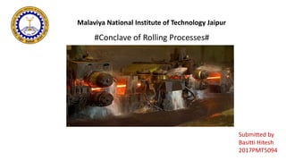
  • 1. Malaviya National Institute of Technology Jaipur #Conclave of Rolling Processes# Submitted by Basitti Hitesh 2017PMT5094
  • 2. Early equipment for metal rolling The equipment that followed to create sheet products proved to be of very simple design. It is not known who created the first rolling mill. However, one of the earliest drawings is by Leonardo da Vinci. It even shows the need for larger diameter backup rolls to support longer, smaller diameter work rolls as shown in the fig. 15th – 17th century In the middle of the fifteenth century small mills produced gold lace, and other decorative work, in soft metals. There is evidence for rolling of lead and tin on simple 2-high mills with cast-iron rolls at the beginning of the seventeenth century.
  • 3.
  • 4.
  • 6. Definition of Rolling Process The process of plastically deforming metal by passing it between rolls is known as Rolling. Rolling is a process of reducing the thickness (or changing the cross- section) of a long work piece by compressive forces applied through a set of rolls. Rolling is a metal forming process in which stock is passed through one or more pairs of rolls to reduce the thickness and to make thickness uniform.
  • 7. Rolling Process Hot Rolling Cold Rolling Done above Recrystallization Temperature (Tᵣ) Done below Room temperature
  • 8. Typical arrangement of rollers for rolling mills Two High Mill,(Pull over) The stock is returned to the entrance for further reduction
  • 9. Typical arrangement of rollers for rolling mills Two High Mill (Reversing) The work can be passed back and forth through the rolls by reversing their direction of rotation.
  • 10. Typical arrangement of rollers for rolling mills Three High Rolling Mill Consists of Upper and Lower driven rolls and a middle roll, which rotates by friction.
  • 11. Typical arrangement of rollers for rolling mills  This is based on the principle that small-diameter rolls lower the roll forces and reduce Spreading.  Moreover, when worn or broken, small rolls can be replaced at less cost than can large ones.  However, small rolls deflect more under roll forces and have to be supported by other rolls.
  • 12. Typical arrangement of rollers for rolling mills
  • 13. Typical arrangement of rollers for rolling mills Cluster (Sendzimir) Mill  Each of the work rolls is supported by two backing rolls.  Although the cost of a Sendzimir mill facility can be millions of dollars, it is particularly suitable for cold rolling thin sheet of High-Strength metals.
  • 14. Typical arrangement of rollers for rolling mills Continuous (Tandem) Rolling Mill • Here, uses a series of rolling mill and each set is called a stand. • The strip will be moving at different velocity at each stage in the mill. • Used for cold rolling of Steel sheets, Al, Cu alloys. • High Capacity and low labor cost.
  • 15.  The speed of each set of rolls is synchronized so that the input speed of each stand is equal to the output speed of preceding stand.  The uncoiler and wind up reel not only feed the stock into the rolls and coiling up the final product but also provide back tension and front tension to the strip. Tandem Rolling Mill (contd..)
  • 16. Typical arrangement of rollers for rolling mills Planetary rolling mill • Consists of a pair of heavy backing rolls surrounded by a large no. of planetary rolls. • Each planetary rolls gives an almost constant reduction to the slab. • As each pair of planetary rolls ceases to have contact with the work piece, another pair of rolls makes contact and repeat that reduction. • The overall reduction is the summation of a series of small reductions by each pair of rolls. Therefore, the planetary mill can reduces a hot slab directly to strip in one pass through the mill. • The operation requires feed rolls to introduce the slab into the mill, and a pair of planishing rolls on the exit to improve the surface finish.
  • 17. Types of Planetary Rolling Mill
  • 18. Rolling Processes • Continuous Rolling • Transverse Rolling • Shaped Rolling or Section Rolling • Ring Rolling • Powder Rolling • Continuous Casting and Hot Rolling • Thread Rolling
  • 19. Continuous Rolling (Conventional Hot or Cold Rolling) The objective is to decrease the thickness of the metal with an increase in length and with little increase in width.
  • 20. Transverse Rolling or Roll Forging or Cross Rolling In this operation, the cross section of a round bar is shaped by passing it through a pair of rolls with profiled grooves. Roll forging typically is used to produce tapered shafts and leaf springs, table knives, and hand tools. Here, rolls are revolved in one direction.
  • 21. Shaped Rolling or Section Rolling A special type of cold rolling in which flat slab is progressively bent into complex shapes by passing it through a series of driven rolls. No appreciable change in the thickness of the metal during this process. Suitable for producing molded sections such as irregular shaped channels and trim.
  • 22. Ring Rolling (Seamless rings) Here, a thick ring is expanded into a large diameter thinner one. The ring is placed between two rolls, one of the which is driven while the other is idle. Its thickness is reduced by bringing the rolls closer together as they rotate. Typical applications are large rings for rockets and turbines.
  • 23.
  • 24. Powder Rolling Metal powder is introduced between the rolls and compacted into a green strip, which is subsequently sintered and subjected to further hot working and/or cold working and annealing cycles. Advantages • Cut down the initial hot ingot breakdown step. • Economical • Minimize contamination in hot rolling. • Provide fine grain size with a minimum of preferred orientation.
  • 25. Continuous casting and Hot Rolling Metal is melted, cast and hot rolled continuously through a series of rolling mills within the same process. Usually for steel sheet production.
  • 26.
  • 27. The main benefits from the direct rolling technology are:  Low Capital investment for main equipment in case of green field units.  Low Operational cost of rolled steel depending on unit costs  Low inventory and working-capital requirements  Reduced requirements of personnel / manpower.  Reduced civil works and infrastructure costs.  Reduced energy consumption.  Smooth mill operation due to consistent temperature of the input stock.  Higher product yield& consistent quality product.  Low CO2 emissions.  Saving of space.  Production of finished rolled products from scrap in lesser time.
  • 28. Thread Rolling  Dies are pressed against the surface of cylindrical blank. As the blank rolls against the in-feeding die faces, the material is displaced to form the roots of the thread, and the displaced material flows radially outward to form the thread’s crest.  The grain structure of the material is not cut, but is distorted to follow the thread form.  Rolled threads are produced in a single pass at speeds far in excess of those used to cut threads.  The resultant thread has a greater resistance to mechanical stress and an increase in fatigue strength. Also the surface is burnished and work hardened.
  • 29. Analysis of Rolling process Assumptions 1. The arc of contact between the rolls and the metal is a part of a circle. 2. The co-efficient of friction, ‘μ’ is constant in theory, but in reality ‘μ’ varies along the arc of contact. 3. The metal is considered to deform plastically during rolling. 4. The volume of metal is constant before and after rolling. In practical, the volume might decrease a little bit due to close-up of pores. 5. The velocity of the rolls is assumed to be constant. 6. The metal only extends in the rolling direction and no extension in the width of the material. 7. The cross sectional area normal to the rolling direction is not distorted.
  • 30. Since, there is no change in metal volume at a given pt. per unit time throughout the process. Where ‘b’ is the width of the sheet ‘v’ is the velocity of any thickness ‘h’ intermediate between ho & hf When ho ˃ hf, we then have vo ˂ vf The velocity of the sheet must steadily increase from entrance to exit such that a vertical element in the sheet remain undistorted.
  • 31. At a point along the surface of contact between the roll and the sheet, two forces act on the metal: 1) a radial force Pr and 2) a tangential frictional force F. At one pt. along the contact length, called the Neutral point or No slip point, the velocity of the strip is the same as that of the roll. To the left of this pt., the roll moves faster than the strip, to the, to the right of this pt., the strip moves faster than the roll.
  • 32. Because the surface speed of the rigid roll is constant, there is relative sliding between the roll and the strip along the arc of contact in the roll gap. The amount of slip between the rolls and the work can be measured by means of the forward slip, a term used in rolling that is defined: Where s = forward slip vf = final (exiting) work velocity, m/s (ft/sec) and vr = roll speed, m/s (ft/sec).
  • 33. The roll pull the material into the roll gap through a net frictional force on the material. It can be seen that this net frictional force must be to the right; consequently, the frictional force to the left of the neutral pt. must higher than the frictional force to the right. For the workpiece to enter the throat of the roll, the component of the friction force must be equal to or greater than the horizontal component of the normal force. But we know, Therefore, If tan α > μ, the workpiece cannot be drawn. If μ = 0, rolling cannot occur. Therefore Free engagement will occur when μ > tan α
  • 34. The Maximum Reduction (Draft) From triangle ABC, we have As ‘a’ much smaller than ‘R’, we can ignore a². Where ∆h=2a
  • 35. The distribution of roll pressure along the arc of contact shows that the pressure rises to a maximum at the neutral point and then falls off. The pressure distribution does not come to a sharp peak at the neutral point, which indicates that the neutral point is not really a line on the roll surface but an area. The area under the curve is proportional to the rolling load. The area in shade represents the force required to overcome frictional forces between the roll and the sheet. The area under the dashed line AB represents the force required to deform the metal in plane homogeneous compression. The specific roll pressure, ‘p’ is the rolling load divided by the contact area.
  • 36. Roll force Calculation Note that this force appears in the figure as perpendicular to the plane of the strip, rather than at an angle. This is because, in practice, the arc of contact is very small compared with the roll radius, so we can assume that the roll force is perpendicular to the strip without causing significant error in calculations. The roll force in flat rolling can be estimated from the formula Where = average flow stress, MPa (lb/in2); and the product (wL) is the roll- work contact area, mm2 (in2).
  • 37. The main variables in rolling are: • The roll diameter. • The deformation resistance of the metal as influenced by metallurgy, temperature and strain rate. • The friction between the rolls and the workpiece. • The presence of the front tension and/or back tension in the plane of the sheet. We consider in three conditions: 1) No friction condition 2) Normal friction condition 3) Sticky friction condition
  • 38. No friction situation In the case of no friction situation, the rolling load (P) is given by the roll pressure (p) times the area of contact between the metal and the rolls (bLp). Where the roll pressure (p) is the yield stress in plane strain when there is no change in the width (b) of the sheet.
  • 39. Normal friction situation In the normal case of friction situation in plane strain, the average pressure p can be calculated as. Where Q = μLp/h h = the mean thickness between entry and exit from the rolls. We have,
  • 40. Therefore the rolling load P increases with the roll radius √R, depending on the contribution from the friction hill. • The rolling load also increases as the sheet entering the rolls becomes thinner (due to the term eQ). • At one point, no further reduction in thickness can be achieved if the deformation resistance of the sheet is greater than the roll pressure. The rolls in contact with the sheet are both severely elastically deformed. • Small-diameter rolls which are properly stiffened against deflection by backup rolls can produce a greater reduction before roll flattening become significant and no further reduction of the sheet is possible. Example: The rolling of aluminium cooking foil. Roll diameter < 10 mm with as many as 18 backing rolls.
  • 41. Sticky friction situation Continuing the analogy with compression in plane strain And,
  • 42. The torque in rolling can be estimated by assuming that the roll force is centered on the work as it passes between the rolls, and that it acts with a moment arm of one-half the contact length L. Thus, torque for each roll is T=0.5FL The power required per roll can be estimated by assuming that (F) acts in the middle of the arc of contact; thus, in Fig. (5-4), a = L/2. Therefore, the total power (for two rolls), in S.I. units, is Power (in kW) Where F is in newtons , L is in meters, and N is the revolutions per minute of the roll. In traditional English units, the total power can be expressed as Torque, and Power requirements
  • 43. Defects Roll Bending Because of the forces acting on them, rolls undergo changes in shape during rolling. Just as a straight beam deflects under a transverse load, roll forces tend to bend the rolls elastically during rolling.
  • 44. Insufficient camber Possible effects of insufficient camber (a) : edge wrinkling (b), warping (c), centerline cracking (d), and (e) residual stresses.
  • 45. Over camber Effects of over-cambering(a): residual stresses(b), edge cracking (c), centerline splitting (d), and (e). wavy center
  • 46. Classification of Defects Change in rollers orientation causing formation of wavy edges on rolled sheets.
  • 47. Edge cracking  Steels used for machining automotive or precision machinery parts contain non-metallic inclusions like MnS or metallic inclusions such as Pb,Bi,Sn etc.  Homogeneous distribution of such inclusions throughout the metal surface is required to ensure excellent machinability.  But sometimes non-uniform distribution of such inclusions result in the formation of brittle interfaces in the matrix which act as crack initiation sites.  Because of the existence of these brittle interfaces steels subjected to rolling hardly have sufficient deformability.  As a result, cracking occurs along the edges during hot rolling of free machining steel billets and wire rods.
  • 48. Centre line cracking  Centre-line cracking due to rolling process leads to the formation of centre splits whose mechanism of formation is similar to that of edge cracks.  These defects are caused due to non-homogeneous plastic deformation across the width.  Due to rolling pressure, the lateral spread is more towards the edges than the centre.  Due to such non homogeneous deformation, the edges experience tension and the central portions experience compressive stresses.  Such distribution of stresses lead to a split along the central portion in severe cases.
  • 49. Alligatoring Alligatoring will occur when lateral spread is greater in the centre than the surface (surface in tension, centre in compression) and with the presence of metallurgical weakness along the centerline. This type of fracture is accentuated if there is any curling of the sheet because one roll is higher or lower than the centerline of the roll gap.
  • 50. Advancements in Rolling mechanism  Direct linking of cold strip rolling process  Development of endless hot strip rolling  Crown and shape control rolling  Intelligent rolling  Numerical simulation of Rolling process  Reheating furnace technology  Scale control  Rolling lubrication  Cooling of rolled steel  Hard Plate Rolling (HPR) process  Differential Speed Rolling (DSR) process
  • 51. Hard Plate Rolling (HPR) process AZ91 Mg Alloy As cast condition: T.S: 250MPa el.: 5-10% Conventional process: T.S: <~350 MPa el.:<~15% HPR process: T.S: 371MPa el.:23%  The Mg-9Al-1Zn (AZ91) plates processed by HPR consist of coarse grains of 30–60 μm, exhibiting a typical basal texture, fine grains of 1–5 μm and ultrafine (sub) grains of 200–500 nm, both of the latter two having a weakened texture.  The superior properties should be mainly attributed to the cooperation effect of the multimodal grain structure and weakened texture, where the former facilitates a strong work hardening while the latter promotes the basal slip.
  • 52. Differential Speed Rolling (DSR) process Hydrostatic SPD methods such as cyclic extrusion compression (CEC), equal-channel angular pressing (ECAP), and high-pressure torsion (HPT). In SPD processes, the material is subjected to a very large plastic deformation (true strain ε is even greater than 80) usually being conducted under a hydrostatic pressure and room temperature conditions. These SPD methods also exhibit some serious disadvantages, e.g., a poor process efficiency, small dimensions of produced (semi-) products, or a necessity of using specialized machines and tools.
  • 53. a) Normal rolling b) DDR c)DFR d) DSR A differential speed rolling (DSR) is a modification of the rolling process which involves a deformation with different values of a rotational speed of the upper and the lower rolls. This kind of processing belongs to the group of asymmetric rolling processes that have been already introduced to a large-scale production of flat steel products. DSR (cont.) The main characteristic of the DSR method is a value of a rolls speed differentiation coefficient R defined as a ratio of the upper to lower rolls speed.
  • 54. Roumina and Sinclair reported that the differentiation of rolls speed results with a shifting of so-called neutral points (the position where the sheet velocity equals the roll velocity) on upper and lower surfaces of the sample. The neutral point associated with the slow roll is shifted toward the entrance of the roll gap, while the neutral point associated with the fast roll is moved toward the exit of the roll gap. DSR (cont.)
  • 55. Kim et al. reported that in oxygen-free copper, submicron grain size of 820 nm is obtained after the 65 % thickness reduction in a single rolling pass by the DSR method (the R = 3). This processing also leads to a formation of a large fraction of high-angle grain boundaries (HAGBs) (~60 %) and maintaining a high electrical conductivity (that proves a low level of structure defects).
  • 56. Jiang et al. [22] on pure aluminum subjected to the DSR process. The authors found that the cold rolling (with the R = 3) of commercially pure aluminum to 90 % of thickness reduction leads to a formation of microstructure composed of submicron-equiaxed grains and a high fraction of HAGBs (~50 %).
  • 57.
  • 59.