
Recommended
More Related Content
What's hot
What's hot (20)
Similar to Fundamentals of power system
Similar to Fundamentals of power system (20)
Recently uploaded
Recently uploaded (20)
Fundamentals of power system
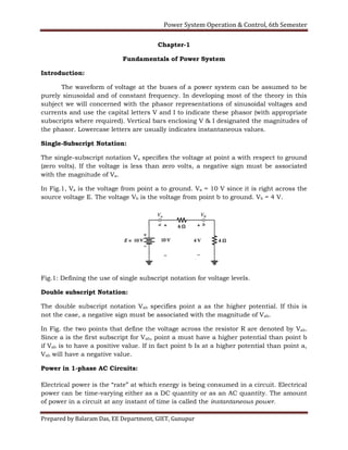
- 1. Power System Operation & Control, 6th Semester Prepared by Balaram Das, EE Department, GIET, Gunupur Chapter-1 Fundamentals of Power System Introduction: The waveform of voltage at the buses of a power system can be assumed to be purely sinusoidal and of constant frequency. In developing most of the theory in this subject we will concerned with the phasor representations of sinusoidal voltages and currents and use the capital letters V and I to indicate these phasor (with appropriate subscripts where required). Vertical bars enclosing V & I designated the magnitudes of the phasor. Lowercase letters are usually indicates instantaneous values. Single-Subscript Notation: The single-subscript notation Va specifies the voltage at point a with respect to ground (zero volts). If the voltage is less than zero volts, a negative sign must be associated with the magnitude of Va. In Fig.1, Va is the voltage from point a to ground. Va = 10 V since it is right across the source voltage E. The voltage Vb is the voltage from point b to ground. Vb = 4 V. Fig.1: Defining the use of single subscript notation for voltage levels. Double subscript Notation: The double subscript notation Vab specifies point a as the higher potential. If this is not the case, a negative sign must be associated with the magnitude of Vab. In Fig. the two points that define the voltage across the resistor R are denoted by Vab. Since a is the first subscript for Vab, point a must have a higher potential than point b if Vab is to have a positive value. If in fact point b Is at a higher potential than point a, Vab will have a negative value. Power in 1-phase AC Circuits: Electrical power is the “rate” at which energy is being consumed in a circuit. Electrical power can be time-varying either as a DC quantity or as an AC quantity. The amount of power in a circuit at any instant of time is called the instantaneous power.
- 2. Power System Operation & Control, 6th Semester Prepared by Balaram Das, EE Department, GIET, Gunupur For DC circuit, Where: V is the dc voltage, I is the dc current and R is the value of the resistance. For AC circuit, Complex Power: Complex power is “the complex sum of real and reactive powers”. It is also termed as apparent power, measured in terms of Volt Amps (or) in Kilo Volt Amps (kVA). The rectangular power of complex power is given below: Where, S is complex or apparent power, P is real power measured in terms of Watts and Q is reactive power measured in terms of Volt Amps Reactive (generally in kVAR). The polar form of complex power is given below: In addition, the complex power for transformer can be written as, S=VI. The complex power for transmission lines is, S=VI*, where I* is complex conjugate of current. The magnitude of the complex power is the apparent power. The Power Triangle: Power Triangle is the representation of a right angle triangle showing the relation between active power, reactive power and apparent power.
- 3. Power System Operation & Control, 6th Semester Prepared by Balaram Das, EE Department, GIET, Gunupur The power which is actually consumed or utilized in an AC Circuit is called True power or Active Power or real power. It is measured in kilowatt (kW) or MW. The power which flows back and forth that means it moves in both the direction in the circuit or reacts upon it, is called Reactive Power. The reactive power is measured in kVAR or MVAR. The product of RMS value of voltage and current is known as Apparent Power. This power is measured in KVA or MVA. Direction of Power Flow: Example 1.1. Two ideal voltage sources designated as machines 1 and 2 are connected, as shown in Fig. If E1 = 100 V, E2 = 100∟30° V, and Z = 0 + j5 Ω, determine (a) whether each machine is generating or consuming real power and the amount, (b) whether each machine is receiving or supplying reactive power and the amount, and (c) the P and Q absorbed by the impedance.
- 4. Power System Operation & Control, 6th Semester Prepared by Balaram Das, EE Department, GIET, Gunupur Solution: Current entering box-1 = -I Current entering box-2 = I Reactive power absorbed in the series impedance is NOTE: Machine-1 may be expected to be a generator because of the current direction and polarity markings. However, since P1 is positive and Q1 is negative, the machine consumes energy at the rate of 1000W and supplies reactive power of 268 VAR. The machine is actually a motor. Machine-2, expected to be a motor, has negative P2 and negative Q2. Therefore, this machine generates energy at the rate of 1000W and supplies reactive power of 268 VAR. The machine is actually a generator. Note that the supplied reactive power of 268 + 268 =536 VAR, which is required by the inductive reactance of j5Ω. Since the impedance is purely reactive, no P is consumed by the impedance, and all the watts generated by machine 2 are transferred to machine 1. Voltage and Current in Balanced Three Phase Circuits Star Connection (Y)
- 5. Power System Operation & Control, 6th Semester Prepared by Balaram Das, EE Department, GIET, Gunupur Star Connection is obtained by connecting together similar ends of the three coils. The other ends are joined to the line wires. The common point is called the neutral. Star Connection, is also called Three Phase 4 wires system. The Voltage between Line and Neutral is called Phase voltage and the voltage between two Lines is called Line Voltage. Star Connection Delta Connection It is seen from the fig 2 that; Line voltages are 120° apart from each other
- 6. Power System Operation & Control, 6th Semester Prepared by Balaram Das, EE Department, GIET, Gunupur Line voltages are 30° leading from the corresponding phase voltages The angle Ф between line currents and respective line voltages are (30°+Ф), i.e. each line current is lagging (30°+Ф) from the corresponding line voltage. Example 1.2: A balanced Y-connected load of 8+j6 Ω per phase connected to a balanced 3- phase 400V supply. Find the line current, power factor, power and total volt amp. Solution: Example 1.3 A balanced three-phase load connected in star consists of (6+8) Ω impedance in each phase. It is connected to a three phase supply of 400 V, 50 Hz. Find (i) Phase current (ii) Line current (iii) Per phase power and (iv) Total power.
- 7. Power System Operation & Control, 6th Semester Prepared by Balaram Das, EE Department, GIET, Gunupur Per-unit quantities: The per unit value of any quantity is defined as the ratio of actual value in any unit and the base or reference value in the same unit. The per unit value are dimensionless. Actual Quantity Base Quantity Voltage, V1 Current, I1 Base Voltage, VB Base Current, IB
- 8. Power System Operation & Control, 6th Semester Prepared by Balaram Das, EE Department, GIET, Gunupur Resistance, R1 Reactance, X1 Active power, P1 Reactive power, Q1 Impedance, Z1 Base Power, SB Base Impedance, ZB Out of four base quantity, SB and VB …….selected base quantity ZB and IB ………derived base quantity from selected base For a single-phase system, the following formulas relate the various quantities. Per unit values Voltage in pu Current in pu Resistance in pu Reactance in pu Active power in pu Reactive power in pu Impedance in pu Advantages of per-unit calculation 1. Manufacturers usually specify the impedance of a piece of apparatus in percent or per-unit on the base of the name plate rating. 2. The per-unit impedances of machines of same type and widely different rating usually lie within narrow range. 3. For a transformer, when impedance in ohm is specified, it must be clearly mentioned whether it is with respect to primary or secondary. The per-unit
- 9. Power System Operation & Control, 6th Semester Prepared by Balaram Das, EE Department, GIET, Gunupur impedance of the transformer, once expressed on proper base, is the same referred to either side. 4. The way in which the three-phase transformers are connected does not affect the per-unit impedances although the transformer connection does determine the relation between the voltage bases on the two sides of the transformer. 5. Calculation using pu system is easier. Changing the Base in Per- Unit Quantities: (or, Per-unit quantities on a different base: From eq.() It is to be noted that the per-unit impedance is directly proportional to base MVA and inversely proportional to (base kV)2. Therefore, to change from per-unit impedance on a given base to per-unit impedance on a new base, the following equation applies: System-01 System-02 From equation(21) and (22) Example: 1.4 A three phase 500 MVA, 22 kV generator has winding reactance of 1.065 Ω. Find its per unit reactance. Solution:
- 10. Power System Operation & Control, 6th Semester Prepared by Balaram Das, EE Department, GIET, Gunupur Example: 1.5 The reactance of a generator is given as 0.25 per-unit based on the generator’s of 18 kV, 500 MVA. Find its per-unit reactance on a base of 20 kV, 100 MVA. Solution: Node Equations: Once the per-unit equivalent circuit is created, it can be used to determine the voltages, currents, and powers at various points. The most common technique used to solve such circuits is nodal analysis. To simplify the equations, Replace the generators by their Norton equivalent circuits Replace the impedances by their equivalent admittances Represent the loads by the current they draw (for now) Kirchhoff’s current flow law (KCL) can be used to establish and solve a system of simultaneous equations with the unknown node voltages. Assuming that the current from the current sources are entering each node, and that all other currents are leaving the node, applying the KCL to the 3 nodes yields
- 11. Power System Operation & Control, 6th Semester Prepared by Balaram Das, EE Department, GIET, Gunupur In matrix from, ………..(25) Which is an equation of the form: Where Ybus is the bus admittance matrix of the system. Ybus has a regular form that is easy to calculate: The diagonal elements Yii equal the sum of all admittances connected to node i. Other elements Yij equal to the negative admittances connected to nodes I and j. The diagonal elements of Ybus are called the self admittance or driving point admittances of the nodes; the off diagonal elements are called the mutual admittances or transfer admittances of the nodes. The Single Line or One Line Diagram: The single-line diagram is the blueprint for electrical system analysis. It is the first step in preparing a critical response plan, allowing you to become thoroughly familiar with the electrical distribution system layout and design in your facility. Whether you have a new or existing facility, the single-line diagram is the vital roadmap for all future testing, service and maintenance activities. Application: Short circuit calculations Coordination studies Load flow studies Safety evaluation studies All other engineering studies Electrical safety procedures Efficient maintenance The single line diagram uses single line and symbols to represent the path and the components of an electrical circuit. These diagrams are specifically use when the information about the circuit is required but the details of the actual wire connection and the operation of the circuit are not needed. The single diagram provides an easy and understanding of the connection and the component.
- 12. Power System Operation & Control, 6th Semester Prepared by Balaram Das, EE Department, GIET, Gunupur Importance of single line diagram 1. Identification of the problem location, in safety conformity and the staff safety can be benefited by the use of single line diagram. 2. If in any case the inaccuracy in the connection and the failure arises the updation of the single diagram becomes easy even on the regular basis. 3. The information from one line diagram can be widely used to enhance the performance of service activities. 4. The single line diagram can be termed as building an electrical system. Construction of single line diagram 1. As we know that the single line diagram is a simplified way for representing a 3 phase power system, so in case of representing each of the 3 phases with a separate terminal only one conductor is used to represent it. 2. The electrical elements like transformer, capacitor, circuit breaker, bus bars are represented by the standard schematic symbols. 3. It is to be noted that the elements portrait on the diagram doesnot represent actual physical size of the electrical component. 4. The component of the diagram are arranged in the order of the decreasing voltage level i.e the component with the highest voltage is present at the top right of the diagram and hence forth. Impedance and reactance diagram
- 13. Power System Operation & Control, 6th Semester Prepared by Balaram Das, EE Department, GIET, Gunupur In order to calculate the performance of a power system under load condition or upon the occurrence of a fault, the one line diagram is used to draw the single-phase or per phase equivalent circuit of the system. Refer the one-line diagram of a sample power system shown in Fig. 1.4. Fig.1.9 combines the equivalent circuits for the various components shown in Fig. 1.4 to form the per-phase impedance diagram of the system. The impedance diagram does not include the current limiting impedances shown in the one-line diagram because no current flows in the ground under balanced condition. Short Questions with answers
- 14. Power System Operation & Control, 6th Semester Prepared by Balaram Das, EE Department, GIET, Gunupur 1. What is per unit system? Why it is used for the studies of power system? Ans: The per unit value of any electrical quantity is defined as the ratio of the actual value of the quantity to its base value expressed as a decimal. It is used for the studies of power system due because PU system makes the calculation refereed to power system simple. 2. List the advantages of per unit computations. a. The per unit impedance referred to either side of a single phase transformer is the same. b. The per unit impedance referred to either side of a three phase transformer is the same regardless of the three phase connections whether they are Y-Y, Δ-Δ or Δ-Y c. The chance of confusion between the line and phase quantities in a three phase balanced system is greatly reduced. d. The manufacturers usually provide the impedance values in per unit. e. The computational effort in power system is very much reduced with the use of per unit quantities. 3. What is single line diagram in power system and explain its importance? The single line diagram of a power system is the network which shows the main connections and arrangement of the system components along with their data (such as output rating, voltage, resistance and reactance, etc.). 4. Write the equation for converting the per unit impedance expressed in one base to another. 5. What are various sources of reactive power? Explain its significance. The sources of reactive power are generators, capacitors, and reactors. 6. A single phase AC voltage of 250 is supplied to a series circuit whose impedance is 5+j8. Find R,X,P and Q and the power factor of the circuit.
- 15. Power System Operation & Control, 6th Semester Prepared by Balaram Das, EE Department, GIET, Gunupur 7. What is complex power? Complex power is “the complex sum of real and reactive powers”. It is also termed as apparent power, measured in terms of Volt Amps (or) in Kilo Volt Amps (kVA). The rectangular power of complex power is given below: The polar form of complex power is given below: In addition, the complex power for transformer can be written as, S=VI. The complex power for transmission lines is, S=VI*, where I* is complex conjugate of current. The magnitude of the complex power is the apparent power. 8. What do you mean by reactance diagram of the power system and explain its importance. The reactance diagram is the simplified equivalent circuit of power system in which the various components of power system are represented by their reactances. The reactance diagram can be obtained from impedance diagram if all the resistive components are neglected. The reactance diagram is used for fault calculations. 9. What is the need for selecting a base value for pu representation? The components or various sections of power system may operate at different voltage and power levels. It will be convenient for analysis of power system if the voltage, power, current and impedance rating of components of power system are expressed with reference to a common value called base value. 10. The reactance of a generator is given as 0.25 per-unit based on the generator’s of 18 kV, 500 MVA. Find its per-unit reactance on a base of 20 kV, 100 MVA. Solution:
- 16. Power System Operation & Control, 6th Semester Prepared by Balaram Das, EE Department, GIET, Gunupur