UDP and TCP Protocol & Encrytion and its algorithm
•Download as DOCX, PDF•
2 likes•758 views

Assignment of Transport Layer including "UDP and TCP Protocol"

Recommended
More Related Content
What's hot
What's hot (20)
Similar to UDP and TCP Protocol & Encrytion and its algorithm
Similar to UDP and TCP Protocol & Encrytion and its algorithm (20)
More from Ayesha Tahir
Recently uploaded
Recently uploaded (20)
UDP and TCP Protocol & Encrytion and its algorithm
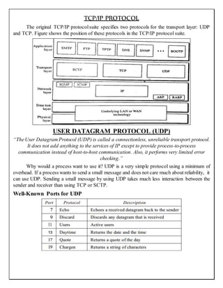
- 1. TCP/IP PROTOCOL The original TCP/IP protocolsuite specifies two protocols for the transport layer: UDP and TCP. Figure shows the position of these protocols in the TCP/IP protocol suite. USER DATAGRAM PROTOCOL (UDP) “TheUser Datagram Protocol (UDP) is called a connectionless, unreliable transport protocol. It does not add anything to the services of IP except to provide process-to-process communication instead of host-to-host communication. Also, it performs very limited error checking.” Why would a process want to use it? UDP is a very simple protocol using a minimum of overhead. If a process wants to send a small message and does not care much about reliability, it can use UDP. Sending a small message by using UDP takes much less interaction between the sender and receiver than using TCP or SCTP. Well-Known Ports for UDP
- 2. USER DATAGRAM FORMATE: UDP packets, called user datagrams, have a fixed-size header of 8 bytes. Figure shows the format of a user datagram. The fields are as follows: SOURCE PORT NUMBER: This is the portnumber used bythe process running on the source host. It is 16 bits long, which means that the port number can range from 0 to 65,535. If the source host is the client (a client sending a request), the portnumber, in most cases, is an ephemeral port number requested by the process and chosen by the UDP software running on the source host. If the source host is the server (a server sending a response), the portnumber, in most cases, is a well-known portnumber. DESTINATION PORTNUMBER: This is the port number used by the process running on the destination host. It is also 16 bits long. If the destination host is the server (a client sending a request), the port number, in most cases, is a well-known port number. If the destination host is the client (a server sending a response), the port number, in most cases, is an ephemeral port number. In this case, the server copies the ephemeral port number it has received in the request packet. LENGTH: This is a 16-bit field that defines the total length of the user datagram, header plus data. The 16 bits can define a total length of 0 to 65,535 bytes. However, the total length needs to be much less because a UDP user datagram is stored in an IP datagram with a total length of 65,535 bytes.
- 3. The length field in a UDP user datagram is actually not necessary. A user datagram is encapsulated in an IP datagram. There is a field in the IP datagram that defines the total length. There is another field in the IP datagram that defines the length of the header. So if we subtract the value of the second field from the first, we can deduce the length of a UDP datagram that is encapsulated in an IP datagram. UDP length = IP length - IP header's length However, the designers of the UDP protocolfelt that it was more efficient for the destination UDP to calculate the length of the data from the information provided in the UDP user datagram rather than ask the IP software to supply this information. We should remember that when the IP software delivers the UDP user datagram to the UDP layer, it has already dropped the IP header. CHECKSUM: This field is used to detect errors over the entire user datagram (header plus data). The checksum is discussed next. CHECKSUM: The checksum includes three sections: a pseudo-header, the UDP header, and the data coming from the application layer. The pseudo-header: “is the part of the header of the IP packet in which the user datagram is to be encapsulated with some fields filled with 0s.” If the checksum does not include the pseudo-header, a user datagram may arrive safe and sound. However, if the IP header is corrupted, it may be delivered to the wrong host. The protocolfield is added to ensure that the packet belongs to UDP, and not. The value of the protocolfield for UDP is 17. If this value is changed during transmission, the checksum calculation at the receiver will detect it and UDP drops thepacket. It is not delivered to the wrong protocol. to other transport-layer protocols. USE OF UDP: The following lists some uses of the UDP protocol: UDP is suitable for a process that requires simple request-response communication with little concern for flow and error control. It is not usually used for a process such as FrP that needs to send bulk data. UDP is suitable for a process with internal flow and error control mechanisms. For example, the Trivial File Transfer Protocol(TFTP)process includes flow and error control. It can easily use UDP. UDP is a suitable transport protocolfor multicasting. Multicasting capability is embedded in the UDP software but not in the TCP software. UDP is used for management processessuchas SNMP.
- 4. UDP is used for some route updating protocols suchas Routing Information Protocol(RIP). UDP OPERATIONS: UDP uses concepts commonto the transport layer. These concepts will be discussed here briefly. Connectionless Services As mentioned previously, UDP provides a connectionless service. This means that each user datagram sent by UDP is an independent datagram. There is no relationship between the different user datagrams even if they are coming from the same source process and going to the same destination program. The user datagrams are not numbered. Also, there is no connection establishment and no connection termination, as is the case for TCP. This means that each user datagram can travel on a different path. One of the ramifications of being connectionless is that the process that uses UDP cannot send a stream of data to UDP and expect UDP to chop them into different related user datagrams. Instead each request must be small enough to fit into one user datagram. Only those processes sending short messages should use UDP. Flow and Error Control UDP is a very simple, unreliable transport protocol. There is no flow controland hence no window mechanism. The receiver may overflow with incoming messages. There is no error control mechanism in UDP except for the checksum. This means that the sender does not know if a message has been lostorduplicated. When the receiver detects an error through the checksum, the user datagram is silently discarded. The lack of flow control and error controlmeans that the process using UDP should provide these mechanisms. Encapsulation and De-capsulation To send a message from one process to another, the UDP protocol encapsulates and decapsulates messages in an IP datagram. Queuing We have talked aboutports without discussing the actual implementation of them. In UDP, queues are associated with ports see Figure. TRANSMISSION CONTROL PROTOCOL (TCP) “TCP is called a connection-oriented, reliable transport protocol. It adds connection-oriented and reliability features to the services of IP. It creates a virtual connection between two TCPs to send data. In addition, TCP uses flow and error control mechanismsat the transport level.” TCP, like UDP, is a process-to-process (program-to-program)protocol. TCP, therefore, like UDP, uses port numbers.
- 5. TCP SERVICES: Let us explain the services offered by TCP to the processes at the application layer. Process-to-Process Communication Like UDP, TCP provides process-to-processcommunication using port numbers. Table lists some well-known port numbers used by TCP. Stream Delivery Service TCP, unlike UDP, is a stream-oriented protocol. In UDP, a process (anapplication program) sends messages, with predefined boundaries, to UDP for delivery. UDP adds its own header to each of these messages and delivers them to IP for transmission. Each message from the process is called a user datagram and becomes, eventually, one IP datagram. TCP, on the other hand, allows the sending process to deliver data as a stream of bytes and allows the receiving process to obtain data as a stream of bytes. TCP creates an environment in which the two processes seemto beconnected by an imaginary "tube" that carries their data across the Internet. This imaginary environment is depicted in Figure.
- 6. Sending and Receiving Buffers Because the sending and the receiving processes may not write or read data at the same speed, TCP needs buffers for storage. There are two buffers, the sending buffer and the receiving buffer, one for each direction. One way to implement a buffer is to use a circulararray of I-byte locations as shown in Figure. Forsimplicity, we have shown two buffers of 20 bytes each (which is not always the case); normally the buffers are hundreds or thousands of bytes, depending on the implementation. Figure shows the movement of the data in one direction. At the sending site, the buffer has three types of chambers. The white section contains empty chambers that can be filled by the sending process (producer). The gray area holds bytes that have been sent but not yet acknowledged. TCP keeps these bytes in the buffer until it receives an acknowledgment. The colored area contains bytes to be sent by the sending TCP. Also note that after the bytes in the gray chambers are acknowledged, the chambers are recycled and available for use by the sending process. This is why we show a circular buffer. The operation of the buffer at the receiver site is simpler. The circular buffer is divided into two areas (shown as white and colored). The white area contains empty chambers to be filled by bytes received from the network. The coloredsections contain received bytes that can be read by the receiving process. When a byte is read by the receiving process, the chamber is recycled and added to the pool of empty chambers.
- 7. Segments Although buffering handles the disparity between the speed of the producing and consuming processes, we need one more step before we can send data. The IP layer, as a service provider for TCP, needs to send data in packets, not as a stream of bytes. At the transport layer, “TCP groupsa numberof bytes together intoa packetcalled a segment”. TCPadds aheader to each segment (for control purposes) and delivers the segment to the IP layer for transmission. The segments are encapsulated in IP datagrams and transmitted. This entire operation is transparent to the receiving process. Segments may be received out of order, lost, or corrupted and resent. All these are handled by TCP with the receiving process unaware of any activities. Figure shows how segments are created from the bytes in the buffers. Note that the segments are not necessarily the same size. In Figure, for simplicity, we show one segment carrying 3 bytes and the other carrying 5 bytes. In reality, segments carry hundreds, if not thousands, of bytes. Full-Duplex Communication TCP offers full-duplex service, in which data can flow in both directions at the same time. Each TCP then has a sending and receiving buffer, and segments move in both directions. Connection-Oriented Service TCP, unlike UDP, is a connection-oriented protocol. When a process at site A wants to send and receive data from another process at site B, the following occurs: The two TCPs establish a connection between them. Data are exchanged in both directions. The connection is terminated. Note that this is a virtual connection, not a physical connection. The TCP segment is encapsulated in an IP datagram and can be sent out of order, or lost, or corrupted, and then resent. Each may usea different path to reach the destination. TCP creates astream-oriented environment in which it accepts theresponsibility of delivering the bytes in orderto the other site. The situation
- 8. is similar to creating a bridge that spans multiple islands and passing all the bytes from one island to another in one single connection. Reliable Service TCP is a reliable transport protocol. It uses an acknowledgment mechanism to check the safe and sound arrival of data. Flow Control TCP, unlike UDP, provides flow control. The receiver of the data controls the amount of data that are to be sentby the sender. This is doneto prevent the receiver from being overwhelmed with data. The numbering system allows TCP to use a byte-oriented flow control. Error Control To provide reliable service, TCP implements an error control mechanism. Although error control considers a segment as the unit of data for error detection (loss or corrupted segments), error control is byte-oriented, as we will see later. Congestion Control TCP, unlike UDP, takes into account congestion in the network. The amount of data sent by a sender is not only controlled by the receiver (flow control), but is also detennined by the level of congestion in the network. SEGMENT: Before we discuss TCP in greater detail, let us discuss the TCP packets themselves. A packet in TCP is called a segment. FORMATE: The segment consists ofa 20- to 60-byte header, followed by data from the application program. The header is 20 bytes if there are no options and up to 60 bytes if it contains options. SOURCE PORT ADDRESS:
- 9. This is a 16-bit field that defines the port number of the application program in the host that is sending the segment. This serves the same purposeas the sourceport address in the UDP header. DESTINATION PORT ADDRESS: This is a 16-bit field that defines the port number of the application program in the host that is receiving the segment. This serves the same purposeas the destination portaddress in the UDP header. SEQUENCE NUMBER: This 32-bit field defines the number assigned to the first byte of data contained in this segment. As we said before, TCP is a stream transport protocol. To ensure connectivity, each byte to betransmitted is numbered. The sequencenumber tells the destination which byte in this sequence comprises the first byte in the segment. During connection establishment, each party uses a random number generator to create an Initial Sequence Number (ISN), which is usually different in each direction. ACKNOWLEDGMENT NUMBER: This 32-bit field defines the byte number that the receiver of the segment is expecting to receive from the other party. If the receiver of the segment has successfully received byte number x from the other party, it defines x + I as the acknowledgment number. Acknowledgment and data can be piggybacked together. HEADER LENGTH: This 4-bit field indicates the number of 4-byte words in the TCP header. The length of the header can be between 20 and 60 bytes. Therefore, the value of this field can be between 5 (5 x 4 =20) and 15 (15 x 4 =60). RESERVED: This is a 6-bit field reserved for future use. CONTROL: This field defines 6 different control bits or flags as shown in Figure. One or more of these bits can be set at a time. These bits enable flow control, connection establishment and termination, connection abortion, and the mode of data transfer in TCP.
- 10. WINDOW SIZE: This field defines the size of the window, in bytes, that the other party must maintain. Note that the length of this field is 16 bits, which means that the maximum size of the window is 65,535 bytes. This value is normally referred to as the receiving window (rwnd) and is determined by the receiver. The sender must obey the dictation of the receiver in this case. CHECKSUM: This 16-bit field contains the checksum. The calculation of the checksum for TCP follows the same procedure as the one described for UDP. However, the inclusion of the checksum in the UDP datagram is optional, whereas the inclusion of the checksum for TCP is mandatory. The same pseudo-header, serving the same purpose, is added to the segment. For the TCP pseudo-header, the value for the protocol field is 6. URGENT POINTER: This l6-bit field, which is valid only if the urgent flag is set, is used when the segment contains urgent data. It defines the number that must be added to the sequence number to obtain the number of the last urgent byte in the data section of the segment. OPTIONS: There can be up to 40 bytes of optional information in the TCP header. References: Book: “Data Communication & Networking”, Fourth Edition by Behrouz A. Forouzan Deanza College with Sophia Chung Fegan.