SlideShare a Scribd company logo
1 of 7
Download to read offline
GENERAL DESCRIPTION
The LuminOx Sensor family is a range of factory calibrated oxygen
sensors which measure ambient ppO₂ levels using the principle of
fluorescence quenching by oxygen.
The LuminOx Evaluation interface Board has been designed to allow
customers to quickly and easily evaluate the sensor with the minimum
of effort or design work.
The interface simultaneously provides three outputs:
 RS232 (serial interface voltage levels)
 RS485 (Modbus RTU) port allows multiple sensors to be
addressed on a bus.
 0-5V analogue output for basic measurements of oxygen only.
ELECTRICAL AND ENVIRONMENTAL SPECIFICATION
LuminOx Sensor
Compatibility
0-25% (O2% version)
0-300mbar (ppO2 version)
Resolution
0.01% / 0.1mbar (Digital Outputs)
0.01V (0-5V Analogue Output)
PERFORMANCE SPECIFICATION
Connection 9 Screw terminals
PCB Dimensions 75x55mm max
MECHANICAL
APPLICATIONS
 Oxygen Detection
 Portable Equipment
 Breathing Apparatus
 Inerting
 Medical
 Lab Equipment
 Agriculture
 Incubation
 Fire Prevention
 Flue Gas in Condensing Boilers
Supply Voltage (Vs) 4.75-5.25 Vdc
Supply Current (Is) <50mA
Output Types RS232, RS485 and 0-5V
Operating Temperature 0°C to +50°C
Storage Temperature 0°C to +60°C
 Converts the LuminOx TTL level
RS232 output into 3 standard industrial
outputs
 Auto detects ppO2 or O2% variants of
LuminOx Sensor.
LuminOx
LuminOx Evaluation Interface Board
BENEFITS
Note: LuminOx
sensor sold
separately
The LuminOx range has been designed as an alternative to electrochemical sensors but with the benefits of RoHS compliance, long life
and complete environmental compensation built-in.
The sensor is available with and without a built-in barometric pressure sensor. LuminOx’s native measurement is partial oxygen pressure
(ppO2) in mbar. By incorporating a barometric pressure sensor, LuminOx is able to measure O2 vol. % in addition to ppO2
Unlike electrochemical sensors, LuminOx requires no additional signal conditioning circuitry and connects directly to the customers
microcontroller via 3.3V-level RS232 link. This reduces costs and simplifies system design.
However, to enable customers to quickly evaluate the sensor, the LuminOx Evaluation Interface Board has been developed. It’s three
Output channels are explained below. Wiring details are show on page 7.
RS232 Output:
The RS232 port on the interface board converts the TTL level RS232 to serial levels compatible with the industry standard, allowing direct
connection to industrial RS232 interfaces.
RS232 Setup:
The following setup should be used when using the RS232 interface.
Baudrate: 9600
Flow Control: None
Parity: None
Stop bits: One
Data Length: 8 bits
LuminOx
LuminOx Evaluation Interface Board
RS232 Command Set:
All RS232 communication is performed using ascii characters, Table 1 shows the legal characters for each description block.
There are two modes available: Poll Mode and Stream Mode.
Table 1
Poll Mode (M 1):
Each request is built using a combination of the description blocks. (See Table 1). A typical arrangement will be one of the following formats:
 <Command><Terminator>
 <Command>< Separator><Argument><Terminator>
Each response will be in the following format:
 <Command>< Separator><Argument><Terminator>
Description Block Legal Character(s) Hex
<Command> “M”, ”O”, ”%”, ”T”, ”P”, ”A”, ”#”, “e” 0x4D, 0x4F, 0x25, 0x54, 0x50, 0x41, 0x23, 0x65
<Argument> “0” – “9” 0x30 – 0x39
<Separator> “ “ 0x20
<Terminator> “rn” 0x0D 0x0A
Page 3 of 7
LuminOx
LuminOx Evaluation Interface Board
Table 2 provides a description of all commands and the valid arguments that can be applied to the interface when in Poll Mode (M1). All
commands are case sensitive.
Example 1:
Request (What is the current oxygen partial pressure?):
 Orn” “0x4F 0x0D 0x0A”
Response (210.3mbar):
 O 0210.3rn” “0x4F 0x20 0x30 0x32 0x31 0x30 0x2E 0x33 0x0D 0x0A”
Example 2:
Request (Put LuminOx into streaming mode):
 “M 0rn” “0x4D 0x20 0x30 0x0D 0x0A”
Response (LuminOx is now in streaming mode):
 “M 00rn” “0x4D 0x20 0x30 0x30 0x0D 0x0A”
Command Description Arguments Response
“M” Output Mode 0 = Stream
1 = Poll
“M xxrn”
Where xx equals the Argument
of the command.
“O” Request current ppO2 value N/a “O xxxx.xrn”
Where xxxx.x equals the ppO2
in mBar
“%” Request current O2 value
(only valid for sensors fitted
with barometric pressure
sensor. Otherwise returns
“- - - - - -”)
N/a “% xxx.xxrn”
Where xxx.xx equals the O2 in
percent %
“T” Request current temperature
inside sensor
N/a “T yxx.xrn”
Where y equals the sign ‘-‘ or
‘+’ and xx.x equals the
temperature in °C
“P” Request current barometric
pressure (only valid for sen-
sors fitted with barometric
pressure sensor. Otherwise
returns “- - - -”)
N/a “P xxxxrn”
Where xxxx equals the
pressure in mBar
“e” Sensor Status N/a “e 0000rn” = Sensor Status
Good
“e xxxxrn” = Any other
response contact SST Sensing
for advice.
“A” Request all values
(see above: O, T, P, % and
e)
N/a See Stream Mode (M 0), Page
4.
“#” Sensor Information 0 = Date of manufacture
1 = Serial Number
2 = Software Revision
“# YYYYY DDDDDrn”
“# xxxxx xxxxxrn”
“# xxxxxrn”
Table 2
Page 4 of 7
LuminOx
LuminOx Evaluation Interface Board
Response: Description: Possible Cause: Action
“E 00rn” RS232 Receiver Overflow No <Terminator> received
before overflow.
Check RS232 Setup,
Confirm correct termination.
“E 01rn” Invalid Command Unrecognised
<Command> received.
Check command is valid
Check command is upper Case “M”
instead of “m”
“E 02rn” Invalid Frame Incorrect character in
frame < Separator>.
Check correct separator is used.
“E 03rn” Invalid Argument <Argument> not allowed
or in limits.
Check Argument is no longer than 6
characters long.
Check Argument is within limits
Check Argument is available for
command.
Error Codes
When a request has been unsuccessfully received, an error code may appear in a response format. Table 3 provides more information on
possible causes and actions.
Table 3
Stream Mode (M 0):
By default stream mode is initiated on sensor power-up and will supply an output string approximately once every second. This
provides the data for ppO2 , Temperature, Pressure, O2 and Sensor Status. The format is provided below, for more details on the
Argument see Table 2.
 “O xxxx.x T yxx.x P xxxx % xxx.xx e xxxxrn”
or the equivalent block description:
 <Command>< Separator><Argument>< Separator><Command>< Separator><Argument>< Separator>
<Command>< Separator><Argument>< Separator><Command>< Separator><Argument>< Separator>
<Command>< Separator><Argument><Terminator>”
RS485 Modbus Output:
The Modbus port on the interface board allows multiple sensors to be connected on a single bus and individually
addressed. Background reading is strongly recommended if there is no prior knowledge of Modbus.
A good place to start is on the website: http://www.modbus.org/, where the specification and resources can be
obtained in the technical resources page.
RS485 Modbus Setup
The modbus interface is configured using the following setup:
Modbus mode: RTU
Address: One
Baudrate: 9600
Parity: None
Stopbits: One
Modbus Registers
The current registers available in the interface can be seen in Table 4 on page 5.
Page 5 of 7
LuminOx
LuminOx Evaluation Interface Board
Name Register
Address
Register Type Description
ppO2 0x7531 Input Register = x/10 ppO2
( Where: 0 = 0 ppO2, 2105 = 210.5 ppO2 )
Temperature 0x7532 Input Register = x (signed) / 10 C
( Where: 65231 = -30.5C , 201 = 20.1C )
O2 0x7533 Input Register = x/ 100
( Where: 0 = 0%, 2070 = 20.70% )
Pressure 0x7534 Input Register = x mBar
( Where: 1017 = 1017 mBar)
Sensor Status 0x7535 Input Register 0 = Sensor Status Good
Anything else contact SST for Guidance.
LuminOx Day 0x7536 Input Register Day Number of Manufacture
LuminOx Year 0x7537 Input Register Year of Manufacture
LuminOx ID 0 0x7538 Input Register Serial Number 0
LuminOx ID 1 0x7539 Input Register Serial Number 1
Address 0x9C41 Holding Register Range = 1 to 247 (0x01 to 0xF7)
Default = 1
Baudrate 0x9C42 Holding Register 0 (0x00) = 2400
1 (0x01) = 4800
2 (0x02) = 9600 (Default)
3 (0x03) = 19200
4 (0x04) = 38400
5 (0x05) = 57600
6 (0x06) = 115200
Parity 0x9C43 Holding Register 0 (0x00) = None (Default)
1 (0x01) = Odd
2 (0x02) = Even
Stopbits 0x9C44 Holding Register 0 (0x00) = 1 (Default)
1 (0x01) = 2
Reset and Apply
Changes to
Communication
Settings
0x9C45 Holding Register 0 (0x00) = No Action
1 (0x01) = Reset and Apply Changes to Modbus
Communication Settings
(See Note 1)
0-5V Output
Representation
0x9C46 Holding Register 0 (0x00) = Auto Detect (Default)
1 (0x01) = ppO2
2 (0x02) = O2 %
(See Note 2)
Table 4
Notes:
1. If any changes are made to the holding registers 0x9C41 to 0x9C44 the changes will not be applied until 0x9C45 is
set to “1”. At this point, if the changes made are valid, the new settings will be committed to memory and communica-
tion will be lost until the RS485 master is reconfigured to the same settings.
2. The 0-5V analogue output is default to represent the variant of LuminOx sensor connected to the interface, so if the
sensor attached is a ppO2 variant the 0-5V output will represent 0-300mbar or if the sensor attached is an O2% vari-
ant the 0-5V output will represent 0-25% O2. However when the attached sensor is an O2% variant the auto detect
setting can be overridden so the 0-5V output can represent either ppO2 or O2%. This feature is not compatible with
the ppO2 variant of LuminOx so if this register is changed to “2” in this instance the 0-5V output will remain at 0V.
Page 6 of 7
LuminOx
LuminOx Evaluation Interface Board
Analogue Output:
The analogue output on the interface board simply provides a 0-5V representation of the primary oxygen reading provided by the
attached LuminOx sensor.
If a ppO2 sensor is attached, then the output voltage will represent ppO2. If an O2% sensor is attached, then the voltage will
represent O2%.
ppO2 Variant:
The current ppO2 level can be calculated using Equation 1:
Equation 1
Where : ppO2 = Current ppO2 in mbar
Vmax = 5 Volts
V = Analogue voltage on the signal output
ppO2 Examples:
O2% Variant:
The current O2% level can be calculated using Equation 2:
Equation 2
Where : O2% = Current O2 concentration (%)
Vmax = 5 Volts
V = Analogue voltage on the signal output
O2% Examples:
VVV
V
ppO  60
5
300
max
300
2
VVV
V
O  5
5
25
max
25
%2
Signal Output (Volts) ppO2 (mBar)
0 0
3.5 210
5 300
Signal Output (Volts) O2 (%)
0 0
3.5 17.5
5 25
PART NUMBERING SYSTEM
LOX-EVB
WARNING
All SST Sensing Ltd products are tested under nominal
operating conditions during the production process.
Applications for our products are varied and,as these are
outside our control, specification information provided is
given without legal responsibility. Customers should test
under their own conditions, to ensure that the sensors are
suitable for their intended application.
CAUTION
Do not exceed maximum ratings.
Carefully follow all wiring instructions.
Do not use chemical cleaning agents.
Failure to comply with these instructions may result
in product damage.
It is the customer’s responsibility to ensure that this product is suitable for use in their application. For
technical assistance or advice, please email us: technical@sstsensing.com
For additional information or help in choosing the most suitable sensor for your application, please contact us. We can
provide full application and technical support on all products.
PINOUT:
Pin 1: Vs (+5VDC)
Pin 2: GND (0V)
Pin 3: 0-5V GND (0V)
Pin 4: 0-5V Signal
Pin 5: RS232 Rx
Pin 6: RS232 Tx
Pin 7: RS232/RS485 GND (0V)
Pin 8: RS485 A (+)
Pin 9: RS485 B (-)
Page 7 of 7
General Note: SST Sensing Ltd reserves the right to make changes in product specifications without notice or
liability. All information is subject to SST’s own data and considered accurate at time of going to print.
Please see our website and datasheet: “DS0030” for details of LuminOx sensors which can be used with this interface
board.
Supply Voltage
5VDC is required to operate the
LuminOx Demo Interface (and
sensor). Care should be taken not
to connect the 5V and 0V
connections the wrong way round
as this may damage the interface.
With power supplied correctly the
green LED on the interface will
illuminate. The minimum and
maximum allowable supply
voltages (Vs) are 4.75 to
5.25VDC.
Notes:
1. RS232 Rx and Tx and RS485 A and B (pins 5, 6, 8 and 9) are referenced to the RS232/RS485 GND (pin 7). A
connection should be made between pin 7 and the reference or common connection of the RS232 serial port or
RS485 Bus.
2. Care should be taken when connecting the RS485 A and B connections to your system. The EIA-485 signalling
specification states that signal A is the inverting or '-' pin and signal B is the non-inverting or '+' pin. This is in
conflict with the A and B naming used by a number of differential transceiver manufacturers, including the
transceiver used in the OXY-LC-485 interface. Therefore always ensure the ‘+’ of the OXY-LC-485 interface is
connected to the ‘+’ input of the RS485 Bus and the ‘-’ of the OXY-LC-485 interface is connected to the ‘-’ input of the
LuminOx
LuminOx Evaluation Interface
All dimensions in mm

More Related Content

Similar to Lumin ox optical oxygen sensor evaluation interface board lox-evb

ISKRA MI 454 Measuring Transducer - Datasheet
 ISKRA MI 454 Measuring Transducer - Datasheet ISKRA MI 454 Measuring Transducer - Datasheet
ISKRA MI 454 Measuring Transducer - DatasheetAngus Sankaran
 
rae_mic2_sensors_and_signals for study purposes
rae_mic2_sensors_and_signals for study purposesrae_mic2_sensors_and_signals for study purposes
rae_mic2_sensors_and_signals for study purposes134483
 
Ultrasonic level meter
Ultrasonic level meterUltrasonic level meter
Ultrasonic level meterhandson28
 
VAISALA MHT410 HYDROGEN+MOISTURE-IN-OIL TRANSMITTER NA PRODUCT ORDER GUIDE AN...
VAISALA MHT410 HYDROGEN+MOISTURE-IN-OIL TRANSMITTER NA PRODUCT ORDER GUIDE AN...VAISALA MHT410 HYDROGEN+MOISTURE-IN-OIL TRANSMITTER NA PRODUCT ORDER GUIDE AN...
VAISALA MHT410 HYDROGEN+MOISTURE-IN-OIL TRANSMITTER NA PRODUCT ORDER GUIDE AN...Ricky Henderson
 
A Unique Approach to Developing Sensor Signal Path Solutions
A Unique Approach to Developing Sensor Signal Path SolutionsA Unique Approach to Developing Sensor Signal Path Solutions
A Unique Approach to Developing Sensor Signal Path SolutionsHarold Joseph
 
Bộ điều khiển nhiệt độ (Temperature Controller) Fuji Electric PXF4
Bộ điều khiển nhiệt độ (Temperature Controller) Fuji Electric PXF4Bộ điều khiển nhiệt độ (Temperature Controller) Fuji Electric PXF4
Bộ điều khiển nhiệt độ (Temperature Controller) Fuji Electric PXF4Beeteco
 
Bộ điều khiển nhiệt độ (Temperature Controller) Fuji Electric PXF4
Bộ điều khiển nhiệt độ (Temperature Controller) Fuji Electric PXF4Bộ điều khiển nhiệt độ (Temperature Controller) Fuji Electric PXF4
Bộ điều khiển nhiệt độ (Temperature Controller) Fuji Electric PXF4CTY TNHH HẠO PHƯƠNG
 
03 analog control_sp17
03 analog control_sp1703 analog control_sp17
03 analog control_sp17John Todora
 
05 analog control_sp15
05 analog control_sp1505 analog control_sp15
05 analog control_sp15John Todora
 
Av02 2315en datasheet
Av02 2315en datasheetAv02 2315en datasheet
Av02 2315en datasheetEdwin Aguilar
 
Bộ điều khiển nhiệt độ (Temperature Controller) Fuji Electric PXF9
Bộ điều khiển nhiệt độ (Temperature Controller) Fuji Electric PXF9Bộ điều khiển nhiệt độ (Temperature Controller) Fuji Electric PXF9
Bộ điều khiển nhiệt độ (Temperature Controller) Fuji Electric PXF9Beeteco
 
Bộ điều khiển nhiệt độ (Temperature Controller) Fuji Electric PXF9
Bộ điều khiển nhiệt độ (Temperature Controller) Fuji Electric PXF9Bộ điều khiển nhiệt độ (Temperature Controller) Fuji Electric PXF9
Bộ điều khiển nhiệt độ (Temperature Controller) Fuji Electric PXF9CTY TNHH HẠO PHƯƠNG
 
osw-1x8-multi-channel-rotary-optical-switch-data-sheet-550401.pdf
osw-1x8-multi-channel-rotary-optical-switch-data-sheet-550401.pdfosw-1x8-multi-channel-rotary-optical-switch-data-sheet-550401.pdf
osw-1x8-multi-channel-rotary-optical-switch-data-sheet-550401.pdfGLsun Mall
 

Similar to Lumin ox optical oxygen sensor evaluation interface board lox-evb (20)

ISKRA MI 454 Measuring Transducer - Datasheet
 ISKRA MI 454 Measuring Transducer - Datasheet ISKRA MI 454 Measuring Transducer - Datasheet
ISKRA MI 454 Measuring Transducer - Datasheet
 
Target flowmeter catalog Z100TF
Target flowmeter catalog Z100TFTarget flowmeter catalog Z100TF
Target flowmeter catalog Z100TF
 
rae_mic2_sensors_and_signals for study purposes
rae_mic2_sensors_and_signals for study purposesrae_mic2_sensors_and_signals for study purposes
rae_mic2_sensors_and_signals for study purposes
 
Ultrasonic level meter
Ultrasonic level meterUltrasonic level meter
Ultrasonic level meter
 
VAISALA MHT410 HYDROGEN+MOISTURE-IN-OIL TRANSMITTER NA PRODUCT ORDER GUIDE AN...
VAISALA MHT410 HYDROGEN+MOISTURE-IN-OIL TRANSMITTER NA PRODUCT ORDER GUIDE AN...VAISALA MHT410 HYDROGEN+MOISTURE-IN-OIL TRANSMITTER NA PRODUCT ORDER GUIDE AN...
VAISALA MHT410 HYDROGEN+MOISTURE-IN-OIL TRANSMITTER NA PRODUCT ORDER GUIDE AN...
 
Chapter5 dek3133
Chapter5 dek3133Chapter5 dek3133
Chapter5 dek3133
 
Mag flow
Mag flowMag flow
Mag flow
 
A Unique Approach to Developing Sensor Signal Path Solutions
A Unique Approach to Developing Sensor Signal Path SolutionsA Unique Approach to Developing Sensor Signal Path Solutions
A Unique Approach to Developing Sensor Signal Path Solutions
 
WJ69产品说明书V1.1.pdf
WJ69产品说明书V1.1.pdfWJ69产品说明书V1.1.pdf
WJ69产品说明书V1.1.pdf
 
Bộ điều khiển nhiệt độ (Temperature Controller) Fuji Electric PXF4
Bộ điều khiển nhiệt độ (Temperature Controller) Fuji Electric PXF4Bộ điều khiển nhiệt độ (Temperature Controller) Fuji Electric PXF4
Bộ điều khiển nhiệt độ (Temperature Controller) Fuji Electric PXF4
 
Bộ điều khiển nhiệt độ (Temperature Controller) Fuji Electric PXF4
Bộ điều khiển nhiệt độ (Temperature Controller) Fuji Electric PXF4Bộ điều khiển nhiệt độ (Temperature Controller) Fuji Electric PXF4
Bộ điều khiển nhiệt độ (Temperature Controller) Fuji Electric PXF4
 
MPX5010.pdf
MPX5010.pdfMPX5010.pdf
MPX5010.pdf
 
03 analog control_sp17
03 analog control_sp1703 analog control_sp17
03 analog control_sp17
 
05 analog control_sp15
05 analog control_sp1505 analog control_sp15
05 analog control_sp15
 
Av02 2315en datasheet
Av02 2315en datasheetAv02 2315en datasheet
Av02 2315en datasheet
 
Fx3 s
Fx3 sFx3 s
Fx3 s
 
Fx3 s
Fx3 sFx3 s
Fx3 s
 
Bộ điều khiển nhiệt độ (Temperature Controller) Fuji Electric PXF9
Bộ điều khiển nhiệt độ (Temperature Controller) Fuji Electric PXF9Bộ điều khiển nhiệt độ (Temperature Controller) Fuji Electric PXF9
Bộ điều khiển nhiệt độ (Temperature Controller) Fuji Electric PXF9
 
Bộ điều khiển nhiệt độ (Temperature Controller) Fuji Electric PXF9
Bộ điều khiển nhiệt độ (Temperature Controller) Fuji Electric PXF9Bộ điều khiển nhiệt độ (Temperature Controller) Fuji Electric PXF9
Bộ điều khiển nhiệt độ (Temperature Controller) Fuji Electric PXF9
 
osw-1x8-multi-channel-rotary-optical-switch-data-sheet-550401.pdf
osw-1x8-multi-channel-rotary-optical-switch-data-sheet-550401.pdfosw-1x8-multi-channel-rotary-optical-switch-data-sheet-550401.pdf
osw-1x8-multi-channel-rotary-optical-switch-data-sheet-550401.pdf
 

Recently uploaded

BEST Call Girls In Greater Noida ✨ 9773824855 ✨ Escorts Service In Delhi Ncr,
BEST Call Girls In Greater Noida ✨ 9773824855 ✨ Escorts Service In Delhi Ncr,BEST Call Girls In Greater Noida ✨ 9773824855 ✨ Escorts Service In Delhi Ncr,
BEST Call Girls In Greater Noida ✨ 9773824855 ✨ Escorts Service In Delhi Ncr,noida100girls
 
Lowrate Call Girls In Laxmi Nagar Delhi ❤️8860477959 Escorts 100% Genuine Ser...
Lowrate Call Girls In Laxmi Nagar Delhi ❤️8860477959 Escorts 100% Genuine Ser...Lowrate Call Girls In Laxmi Nagar Delhi ❤️8860477959 Escorts 100% Genuine Ser...
Lowrate Call Girls In Laxmi Nagar Delhi ❤️8860477959 Escorts 100% Genuine Ser...lizamodels9
 
2024 Numerator Consumer Study of Cannabis Usage
2024 Numerator Consumer Study of Cannabis Usage2024 Numerator Consumer Study of Cannabis Usage
2024 Numerator Consumer Study of Cannabis UsageNeil Kimberley
 
M.C Lodges -- Guest House in Jhang.
M.C Lodges --  Guest House in Jhang.M.C Lodges --  Guest House in Jhang.
M.C Lodges -- Guest House in Jhang.Aaiza Hassan
 
Intro to BCG's Carbon Emissions Benchmark_vF.pdf
Intro to BCG's Carbon Emissions Benchmark_vF.pdfIntro to BCG's Carbon Emissions Benchmark_vF.pdf
Intro to BCG's Carbon Emissions Benchmark_vF.pdfpollardmorgan
 
Call Girls In Sikandarpur Gurgaon ❤️8860477959_Russian 100% Genuine Escorts I...
Call Girls In Sikandarpur Gurgaon ❤️8860477959_Russian 100% Genuine Escorts I...Call Girls In Sikandarpur Gurgaon ❤️8860477959_Russian 100% Genuine Escorts I...
Call Girls In Sikandarpur Gurgaon ❤️8860477959_Russian 100% Genuine Escorts I...lizamodels9
 
Vip Dewas Call Girls #9907093804 Contact Number Escorts Service Dewas
Vip Dewas Call Girls #9907093804 Contact Number Escorts Service DewasVip Dewas Call Girls #9907093804 Contact Number Escorts Service Dewas
Vip Dewas Call Girls #9907093804 Contact Number Escorts Service Dewasmakika9823
 
Call Girls in Gomti Nagar - 7388211116 - With room Service
Call Girls in Gomti Nagar - 7388211116  - With room ServiceCall Girls in Gomti Nagar - 7388211116  - With room Service
Call Girls in Gomti Nagar - 7388211116 - With room Servicediscovermytutordmt
 
VIP Call Girl Jamshedpur Aashi 8250192130 Independent Escort Service Jamshedpur
VIP Call Girl Jamshedpur Aashi 8250192130 Independent Escort Service JamshedpurVIP Call Girl Jamshedpur Aashi 8250192130 Independent Escort Service Jamshedpur
VIP Call Girl Jamshedpur Aashi 8250192130 Independent Escort Service JamshedpurSuhani Kapoor
 
Call Girls Navi Mumbai Just Call 9907093804 Top Class Call Girl Service Avail...
Call Girls Navi Mumbai Just Call 9907093804 Top Class Call Girl Service Avail...Call Girls Navi Mumbai Just Call 9907093804 Top Class Call Girl Service Avail...
Call Girls Navi Mumbai Just Call 9907093804 Top Class Call Girl Service Avail...Dipal Arora
 
VIP Kolkata Call Girl Howrah 👉 8250192130 Available With Room
VIP Kolkata Call Girl Howrah 👉 8250192130  Available With RoomVIP Kolkata Call Girl Howrah 👉 8250192130  Available With Room
VIP Kolkata Call Girl Howrah 👉 8250192130 Available With Roomdivyansh0kumar0
 
Progress Report - Oracle Database Analyst Summit
Progress  Report - Oracle Database Analyst SummitProgress  Report - Oracle Database Analyst Summit
Progress Report - Oracle Database Analyst SummitHolger Mueller
 
Keppel Ltd. 1Q 2024 Business Update Presentation Slides
Keppel Ltd. 1Q 2024 Business Update  Presentation SlidesKeppel Ltd. 1Q 2024 Business Update  Presentation Slides
Keppel Ltd. 1Q 2024 Business Update Presentation SlidesKeppelCorporation
 
The CMO Survey - Highlights and Insights Report - Spring 2024
The CMO Survey - Highlights and Insights Report - Spring 2024The CMO Survey - Highlights and Insights Report - Spring 2024
The CMO Survey - Highlights and Insights Report - Spring 2024christinemoorman
 
FULL ENJOY - 9953040155 Call Girls in Chhatarpur | Delhi
FULL ENJOY - 9953040155 Call Girls in Chhatarpur | DelhiFULL ENJOY - 9953040155 Call Girls in Chhatarpur | Delhi
FULL ENJOY - 9953040155 Call Girls in Chhatarpur | DelhiMalviyaNagarCallGirl
 
/:Call Girls In Jaypee Siddharth - 5 Star Hotel New Delhi ➥9990211544 Top Esc...
/:Call Girls In Jaypee Siddharth - 5 Star Hotel New Delhi ➥9990211544 Top Esc.../:Call Girls In Jaypee Siddharth - 5 Star Hotel New Delhi ➥9990211544 Top Esc...
/:Call Girls In Jaypee Siddharth - 5 Star Hotel New Delhi ➥9990211544 Top Esc...lizamodels9
 
VIP Call Girls Pune Kirti 8617697112 Independent Escort Service Pune
VIP Call Girls Pune Kirti 8617697112 Independent Escort Service PuneVIP Call Girls Pune Kirti 8617697112 Independent Escort Service Pune
VIP Call Girls Pune Kirti 8617697112 Independent Escort Service PuneCall girls in Ahmedabad High profile
 
Grateful 7 speech thanking everyone that has helped.pdf
Grateful 7 speech thanking everyone that has helped.pdfGrateful 7 speech thanking everyone that has helped.pdf
Grateful 7 speech thanking everyone that has helped.pdfPaul Menig
 
Call Girls Pune Just Call 9907093804 Top Class Call Girl Service Available
Call Girls Pune Just Call 9907093804 Top Class Call Girl Service AvailableCall Girls Pune Just Call 9907093804 Top Class Call Girl Service Available
Call Girls Pune Just Call 9907093804 Top Class Call Girl Service AvailableDipal Arora
 

Recently uploaded (20)

BEST Call Girls In Greater Noida ✨ 9773824855 ✨ Escorts Service In Delhi Ncr,
BEST Call Girls In Greater Noida ✨ 9773824855 ✨ Escorts Service In Delhi Ncr,BEST Call Girls In Greater Noida ✨ 9773824855 ✨ Escorts Service In Delhi Ncr,
BEST Call Girls In Greater Noida ✨ 9773824855 ✨ Escorts Service In Delhi Ncr,
 
Lowrate Call Girls In Laxmi Nagar Delhi ❤️8860477959 Escorts 100% Genuine Ser...
Lowrate Call Girls In Laxmi Nagar Delhi ❤️8860477959 Escorts 100% Genuine Ser...Lowrate Call Girls In Laxmi Nagar Delhi ❤️8860477959 Escorts 100% Genuine Ser...
Lowrate Call Girls In Laxmi Nagar Delhi ❤️8860477959 Escorts 100% Genuine Ser...
 
2024 Numerator Consumer Study of Cannabis Usage
2024 Numerator Consumer Study of Cannabis Usage2024 Numerator Consumer Study of Cannabis Usage
2024 Numerator Consumer Study of Cannabis Usage
 
Best Practices for Implementing an External Recruiting Partnership
Best Practices for Implementing an External Recruiting PartnershipBest Practices for Implementing an External Recruiting Partnership
Best Practices for Implementing an External Recruiting Partnership
 
M.C Lodges -- Guest House in Jhang.
M.C Lodges --  Guest House in Jhang.M.C Lodges --  Guest House in Jhang.
M.C Lodges -- Guest House in Jhang.
 
Intro to BCG's Carbon Emissions Benchmark_vF.pdf
Intro to BCG's Carbon Emissions Benchmark_vF.pdfIntro to BCG's Carbon Emissions Benchmark_vF.pdf
Intro to BCG's Carbon Emissions Benchmark_vF.pdf
 
Call Girls In Sikandarpur Gurgaon ❤️8860477959_Russian 100% Genuine Escorts I...
Call Girls In Sikandarpur Gurgaon ❤️8860477959_Russian 100% Genuine Escorts I...Call Girls In Sikandarpur Gurgaon ❤️8860477959_Russian 100% Genuine Escorts I...
Call Girls In Sikandarpur Gurgaon ❤️8860477959_Russian 100% Genuine Escorts I...
 
Vip Dewas Call Girls #9907093804 Contact Number Escorts Service Dewas
Vip Dewas Call Girls #9907093804 Contact Number Escorts Service DewasVip Dewas Call Girls #9907093804 Contact Number Escorts Service Dewas
Vip Dewas Call Girls #9907093804 Contact Number Escorts Service Dewas
 
Call Girls in Gomti Nagar - 7388211116 - With room Service
Call Girls in Gomti Nagar - 7388211116  - With room ServiceCall Girls in Gomti Nagar - 7388211116  - With room Service
Call Girls in Gomti Nagar - 7388211116 - With room Service
 
VIP Call Girl Jamshedpur Aashi 8250192130 Independent Escort Service Jamshedpur
VIP Call Girl Jamshedpur Aashi 8250192130 Independent Escort Service JamshedpurVIP Call Girl Jamshedpur Aashi 8250192130 Independent Escort Service Jamshedpur
VIP Call Girl Jamshedpur Aashi 8250192130 Independent Escort Service Jamshedpur
 
Call Girls Navi Mumbai Just Call 9907093804 Top Class Call Girl Service Avail...
Call Girls Navi Mumbai Just Call 9907093804 Top Class Call Girl Service Avail...Call Girls Navi Mumbai Just Call 9907093804 Top Class Call Girl Service Avail...
Call Girls Navi Mumbai Just Call 9907093804 Top Class Call Girl Service Avail...
 
VIP Kolkata Call Girl Howrah 👉 8250192130 Available With Room
VIP Kolkata Call Girl Howrah 👉 8250192130  Available With RoomVIP Kolkata Call Girl Howrah 👉 8250192130  Available With Room
VIP Kolkata Call Girl Howrah 👉 8250192130 Available With Room
 
Progress Report - Oracle Database Analyst Summit
Progress  Report - Oracle Database Analyst SummitProgress  Report - Oracle Database Analyst Summit
Progress Report - Oracle Database Analyst Summit
 
Keppel Ltd. 1Q 2024 Business Update Presentation Slides
Keppel Ltd. 1Q 2024 Business Update  Presentation SlidesKeppel Ltd. 1Q 2024 Business Update  Presentation Slides
Keppel Ltd. 1Q 2024 Business Update Presentation Slides
 
The CMO Survey - Highlights and Insights Report - Spring 2024
The CMO Survey - Highlights and Insights Report - Spring 2024The CMO Survey - Highlights and Insights Report - Spring 2024
The CMO Survey - Highlights and Insights Report - Spring 2024
 
FULL ENJOY - 9953040155 Call Girls in Chhatarpur | Delhi
FULL ENJOY - 9953040155 Call Girls in Chhatarpur | DelhiFULL ENJOY - 9953040155 Call Girls in Chhatarpur | Delhi
FULL ENJOY - 9953040155 Call Girls in Chhatarpur | Delhi
 
/:Call Girls In Jaypee Siddharth - 5 Star Hotel New Delhi ➥9990211544 Top Esc...
/:Call Girls In Jaypee Siddharth - 5 Star Hotel New Delhi ➥9990211544 Top Esc.../:Call Girls In Jaypee Siddharth - 5 Star Hotel New Delhi ➥9990211544 Top Esc...
/:Call Girls In Jaypee Siddharth - 5 Star Hotel New Delhi ➥9990211544 Top Esc...
 
VIP Call Girls Pune Kirti 8617697112 Independent Escort Service Pune
VIP Call Girls Pune Kirti 8617697112 Independent Escort Service PuneVIP Call Girls Pune Kirti 8617697112 Independent Escort Service Pune
VIP Call Girls Pune Kirti 8617697112 Independent Escort Service Pune
 
Grateful 7 speech thanking everyone that has helped.pdf
Grateful 7 speech thanking everyone that has helped.pdfGrateful 7 speech thanking everyone that has helped.pdf
Grateful 7 speech thanking everyone that has helped.pdf
 
Call Girls Pune Just Call 9907093804 Top Class Call Girl Service Available
Call Girls Pune Just Call 9907093804 Top Class Call Girl Service AvailableCall Girls Pune Just Call 9907093804 Top Class Call Girl Service Available
Call Girls Pune Just Call 9907093804 Top Class Call Girl Service Available
 

Lumin ox optical oxygen sensor evaluation interface board lox-evb

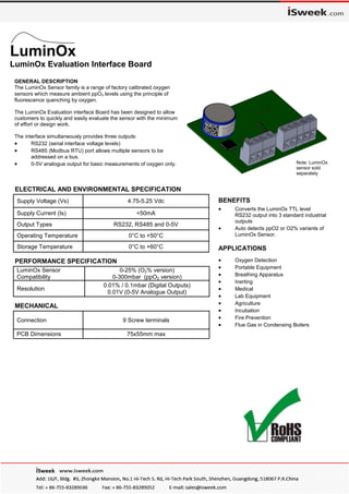
  • 1. GENERAL DESCRIPTION The LuminOx Sensor family is a range of factory calibrated oxygen sensors which measure ambient ppO₂ levels using the principle of fluorescence quenching by oxygen. The LuminOx Evaluation interface Board has been designed to allow customers to quickly and easily evaluate the sensor with the minimum of effort or design work. The interface simultaneously provides three outputs:  RS232 (serial interface voltage levels)  RS485 (Modbus RTU) port allows multiple sensors to be addressed on a bus.  0-5V analogue output for basic measurements of oxygen only. ELECTRICAL AND ENVIRONMENTAL SPECIFICATION LuminOx Sensor Compatibility 0-25% (O2% version) 0-300mbar (ppO2 version) Resolution 0.01% / 0.1mbar (Digital Outputs) 0.01V (0-5V Analogue Output) PERFORMANCE SPECIFICATION Connection 9 Screw terminals PCB Dimensions 75x55mm max MECHANICAL APPLICATIONS  Oxygen Detection  Portable Equipment  Breathing Apparatus  Inerting  Medical  Lab Equipment  Agriculture  Incubation  Fire Prevention  Flue Gas in Condensing Boilers Supply Voltage (Vs) 4.75-5.25 Vdc Supply Current (Is) <50mA Output Types RS232, RS485 and 0-5V Operating Temperature 0°C to +50°C Storage Temperature 0°C to +60°C  Converts the LuminOx TTL level RS232 output into 3 standard industrial outputs  Auto detects ppO2 or O2% variants of LuminOx Sensor. LuminOx LuminOx Evaluation Interface Board BENEFITS Note: LuminOx sensor sold separately
  • 2. The LuminOx range has been designed as an alternative to electrochemical sensors but with the benefits of RoHS compliance, long life and complete environmental compensation built-in. The sensor is available with and without a built-in barometric pressure sensor. LuminOx’s native measurement is partial oxygen pressure (ppO2) in mbar. By incorporating a barometric pressure sensor, LuminOx is able to measure O2 vol. % in addition to ppO2 Unlike electrochemical sensors, LuminOx requires no additional signal conditioning circuitry and connects directly to the customers microcontroller via 3.3V-level RS232 link. This reduces costs and simplifies system design. However, to enable customers to quickly evaluate the sensor, the LuminOx Evaluation Interface Board has been developed. It’s three Output channels are explained below. Wiring details are show on page 7. RS232 Output: The RS232 port on the interface board converts the TTL level RS232 to serial levels compatible with the industry standard, allowing direct connection to industrial RS232 interfaces. RS232 Setup: The following setup should be used when using the RS232 interface. Baudrate: 9600 Flow Control: None Parity: None Stop bits: One Data Length: 8 bits LuminOx LuminOx Evaluation Interface Board RS232 Command Set: All RS232 communication is performed using ascii characters, Table 1 shows the legal characters for each description block. There are two modes available: Poll Mode and Stream Mode. Table 1 Poll Mode (M 1): Each request is built using a combination of the description blocks. (See Table 1). A typical arrangement will be one of the following formats:  <Command><Terminator>  <Command>< Separator><Argument><Terminator> Each response will be in the following format:  <Command>< Separator><Argument><Terminator> Description Block Legal Character(s) Hex <Command> “M”, ”O”, ”%”, ”T”, ”P”, ”A”, ”#”, “e” 0x4D, 0x4F, 0x25, 0x54, 0x50, 0x41, 0x23, 0x65 <Argument> “0” – “9” 0x30 – 0x39 <Separator> “ “ 0x20 <Terminator> “rn” 0x0D 0x0A
  • 3. Page 3 of 7 LuminOx LuminOx Evaluation Interface Board Table 2 provides a description of all commands and the valid arguments that can be applied to the interface when in Poll Mode (M1). All commands are case sensitive. Example 1: Request (What is the current oxygen partial pressure?):  Orn” “0x4F 0x0D 0x0A” Response (210.3mbar):  O 0210.3rn” “0x4F 0x20 0x30 0x32 0x31 0x30 0x2E 0x33 0x0D 0x0A” Example 2: Request (Put LuminOx into streaming mode):  “M 0rn” “0x4D 0x20 0x30 0x0D 0x0A” Response (LuminOx is now in streaming mode):  “M 00rn” “0x4D 0x20 0x30 0x30 0x0D 0x0A” Command Description Arguments Response “M” Output Mode 0 = Stream 1 = Poll “M xxrn” Where xx equals the Argument of the command. “O” Request current ppO2 value N/a “O xxxx.xrn” Where xxxx.x equals the ppO2 in mBar “%” Request current O2 value (only valid for sensors fitted with barometric pressure sensor. Otherwise returns “- - - - - -”) N/a “% xxx.xxrn” Where xxx.xx equals the O2 in percent % “T” Request current temperature inside sensor N/a “T yxx.xrn” Where y equals the sign ‘-‘ or ‘+’ and xx.x equals the temperature in °C “P” Request current barometric pressure (only valid for sen- sors fitted with barometric pressure sensor. Otherwise returns “- - - -”) N/a “P xxxxrn” Where xxxx equals the pressure in mBar “e” Sensor Status N/a “e 0000rn” = Sensor Status Good “e xxxxrn” = Any other response contact SST Sensing for advice. “A” Request all values (see above: O, T, P, % and e) N/a See Stream Mode (M 0), Page 4. “#” Sensor Information 0 = Date of manufacture 1 = Serial Number 2 = Software Revision “# YYYYY DDDDDrn” “# xxxxx xxxxxrn” “# xxxxxrn” Table 2
  • 4. Page 4 of 7 LuminOx LuminOx Evaluation Interface Board Response: Description: Possible Cause: Action “E 00rn” RS232 Receiver Overflow No <Terminator> received before overflow. Check RS232 Setup, Confirm correct termination. “E 01rn” Invalid Command Unrecognised <Command> received. Check command is valid Check command is upper Case “M” instead of “m” “E 02rn” Invalid Frame Incorrect character in frame < Separator>. Check correct separator is used. “E 03rn” Invalid Argument <Argument> not allowed or in limits. Check Argument is no longer than 6 characters long. Check Argument is within limits Check Argument is available for command. Error Codes When a request has been unsuccessfully received, an error code may appear in a response format. Table 3 provides more information on possible causes and actions. Table 3 Stream Mode (M 0): By default stream mode is initiated on sensor power-up and will supply an output string approximately once every second. This provides the data for ppO2 , Temperature, Pressure, O2 and Sensor Status. The format is provided below, for more details on the Argument see Table 2.  “O xxxx.x T yxx.x P xxxx % xxx.xx e xxxxrn” or the equivalent block description:  <Command>< Separator><Argument>< Separator><Command>< Separator><Argument>< Separator> <Command>< Separator><Argument>< Separator><Command>< Separator><Argument>< Separator> <Command>< Separator><Argument><Terminator>” RS485 Modbus Output: The Modbus port on the interface board allows multiple sensors to be connected on a single bus and individually addressed. Background reading is strongly recommended if there is no prior knowledge of Modbus. A good place to start is on the website: http://www.modbus.org/, where the specification and resources can be obtained in the technical resources page. RS485 Modbus Setup The modbus interface is configured using the following setup: Modbus mode: RTU Address: One Baudrate: 9600 Parity: None Stopbits: One Modbus Registers The current registers available in the interface can be seen in Table 4 on page 5.
  • 5. Page 5 of 7 LuminOx LuminOx Evaluation Interface Board Name Register Address Register Type Description ppO2 0x7531 Input Register = x/10 ppO2 ( Where: 0 = 0 ppO2, 2105 = 210.5 ppO2 ) Temperature 0x7532 Input Register = x (signed) / 10 C ( Where: 65231 = -30.5C , 201 = 20.1C ) O2 0x7533 Input Register = x/ 100 ( Where: 0 = 0%, 2070 = 20.70% ) Pressure 0x7534 Input Register = x mBar ( Where: 1017 = 1017 mBar) Sensor Status 0x7535 Input Register 0 = Sensor Status Good Anything else contact SST for Guidance. LuminOx Day 0x7536 Input Register Day Number of Manufacture LuminOx Year 0x7537 Input Register Year of Manufacture LuminOx ID 0 0x7538 Input Register Serial Number 0 LuminOx ID 1 0x7539 Input Register Serial Number 1 Address 0x9C41 Holding Register Range = 1 to 247 (0x01 to 0xF7) Default = 1 Baudrate 0x9C42 Holding Register 0 (0x00) = 2400 1 (0x01) = 4800 2 (0x02) = 9600 (Default) 3 (0x03) = 19200 4 (0x04) = 38400 5 (0x05) = 57600 6 (0x06) = 115200 Parity 0x9C43 Holding Register 0 (0x00) = None (Default) 1 (0x01) = Odd 2 (0x02) = Even Stopbits 0x9C44 Holding Register 0 (0x00) = 1 (Default) 1 (0x01) = 2 Reset and Apply Changes to Communication Settings 0x9C45 Holding Register 0 (0x00) = No Action 1 (0x01) = Reset and Apply Changes to Modbus Communication Settings (See Note 1) 0-5V Output Representation 0x9C46 Holding Register 0 (0x00) = Auto Detect (Default) 1 (0x01) = ppO2 2 (0x02) = O2 % (See Note 2) Table 4 Notes: 1. If any changes are made to the holding registers 0x9C41 to 0x9C44 the changes will not be applied until 0x9C45 is set to “1”. At this point, if the changes made are valid, the new settings will be committed to memory and communica- tion will be lost until the RS485 master is reconfigured to the same settings. 2. The 0-5V analogue output is default to represent the variant of LuminOx sensor connected to the interface, so if the sensor attached is a ppO2 variant the 0-5V output will represent 0-300mbar or if the sensor attached is an O2% vari- ant the 0-5V output will represent 0-25% O2. However when the attached sensor is an O2% variant the auto detect setting can be overridden so the 0-5V output can represent either ppO2 or O2%. This feature is not compatible with the ppO2 variant of LuminOx so if this register is changed to “2” in this instance the 0-5V output will remain at 0V.
  • 6. Page 6 of 7 LuminOx LuminOx Evaluation Interface Board Analogue Output: The analogue output on the interface board simply provides a 0-5V representation of the primary oxygen reading provided by the attached LuminOx sensor. If a ppO2 sensor is attached, then the output voltage will represent ppO2. If an O2% sensor is attached, then the voltage will represent O2%. ppO2 Variant: The current ppO2 level can be calculated using Equation 1: Equation 1 Where : ppO2 = Current ppO2 in mbar Vmax = 5 Volts V = Analogue voltage on the signal output ppO2 Examples: O2% Variant: The current O2% level can be calculated using Equation 2: Equation 2 Where : O2% = Current O2 concentration (%) Vmax = 5 Volts V = Analogue voltage on the signal output O2% Examples: VVV V ppO  60 5 300 max 300 2 VVV V O  5 5 25 max 25 %2 Signal Output (Volts) ppO2 (mBar) 0 0 3.5 210 5 300 Signal Output (Volts) O2 (%) 0 0 3.5 17.5 5 25
  • 7. PART NUMBERING SYSTEM LOX-EVB WARNING All SST Sensing Ltd products are tested under nominal operating conditions during the production process. Applications for our products are varied and,as these are outside our control, specification information provided is given without legal responsibility. Customers should test under their own conditions, to ensure that the sensors are suitable for their intended application. CAUTION Do not exceed maximum ratings. Carefully follow all wiring instructions. Do not use chemical cleaning agents. Failure to comply with these instructions may result in product damage. It is the customer’s responsibility to ensure that this product is suitable for use in their application. For technical assistance or advice, please email us: technical@sstsensing.com For additional information or help in choosing the most suitable sensor for your application, please contact us. We can provide full application and technical support on all products. PINOUT: Pin 1: Vs (+5VDC) Pin 2: GND (0V) Pin 3: 0-5V GND (0V) Pin 4: 0-5V Signal Pin 5: RS232 Rx Pin 6: RS232 Tx Pin 7: RS232/RS485 GND (0V) Pin 8: RS485 A (+) Pin 9: RS485 B (-) Page 7 of 7 General Note: SST Sensing Ltd reserves the right to make changes in product specifications without notice or liability. All information is subject to SST’s own data and considered accurate at time of going to print. Please see our website and datasheet: “DS0030” for details of LuminOx sensors which can be used with this interface board. Supply Voltage 5VDC is required to operate the LuminOx Demo Interface (and sensor). Care should be taken not to connect the 5V and 0V connections the wrong way round as this may damage the interface. With power supplied correctly the green LED on the interface will illuminate. The minimum and maximum allowable supply voltages (Vs) are 4.75 to 5.25VDC. Notes: 1. RS232 Rx and Tx and RS485 A and B (pins 5, 6, 8 and 9) are referenced to the RS232/RS485 GND (pin 7). A connection should be made between pin 7 and the reference or common connection of the RS232 serial port or RS485 Bus. 2. Care should be taken when connecting the RS485 A and B connections to your system. The EIA-485 signalling specification states that signal A is the inverting or '-' pin and signal B is the non-inverting or '+' pin. This is in conflict with the A and B naming used by a number of differential transceiver manufacturers, including the transceiver used in the OXY-LC-485 interface. Therefore always ensure the ‘+’ of the OXY-LC-485 interface is connected to the ‘+’ input of the RS485 Bus and the ‘-’ of the OXY-LC-485 interface is connected to the ‘-’ input of the LuminOx LuminOx Evaluation Interface All dimensions in mm