SlideShare a Scribd company logo
1 of 16
Download to read offline
Med Phys 4R06/6R03 Radioisotopes and Radiation Methodology 3-1
Chapter 3 Gas Filled Detectors
3.1. Ionization chamber
A. Ionization process and charge collection
The interactions of charged particles (either direct charged particles or secondary
particles produced by interactions with photons or neutrons) with a gas lead to ionized
and excited molecules along the path. The important information is the total number of
electron-ion pairs created along the track of the radiation.
The W-value is defined as the average energy lost by the incident particle per ion pair
formed. Due to the competing mechanism of the energy loss, i.e. excitation, W-value is
always greater than the ionization energy. The table below shows W-values for common
gases.
Ionization potential and W-values for different gases.
After being created in the gas, electron-ion pairs are in the random thermal motion and
diffuse away from the high density region. Different types of collisions happen between
free electrons, ions and neutral gas molecules as shown in Fig. 3.1.
+ +
Charge transfer
-
Electron attachment
e-
Recombination
e-
+
+
-
Fig. 3.1. Collisions between free electrons, ions and neutral gas molecules.
Med Phys 4R06/6R03 Radioisotopes and Radiation Methodology 3-2
Charge transfer occurs when a positive ion encounters a neutral molecule. In this case, an
electron is transferred from the neutral molecule to the ion.
When a free electron meets a gas molecule that attaches electrons easily, a negative ion is
formed. Oxygen is a good example. Thus, free electrons diffusing in air are rapidly
converted to negative ions. In contrast, nitrogen, hydrogen and noble gases have low
electron attachment coefficients, and make electrons continuously migrate.
To collect electron-ion pairs produced in a gas-filled detector, an electric field must be
applied. If the electric field inside the detector is strong enough that recombination
becomes negligible, all the charges are efficiently collected without loss. The steady state
current measured at this condition is called ionization current, which is the basic
principle of the DC ion chamber.
I
V
Fig. 3.2. Basic component of an ion chamber and the voltage-current characteristics.
B. Operation of DC ion chambers
When an ion chamber is operated in direct current mode,
the negative charges can be collected either as free
electrons or as negative ions. Thus, any filling gas could be
used. Air is the most common filling gas.
Typical ionization currents in most applications are very
small (1 pA or less). Thus, the leakage current through the
insulator can perturb measuring the ionization current.
Fig. 3.3. Ion chamber employing guard ring.
For example, if we want to keep the leakage current at 1 % level of an ionization current
of 1 pA for an applied voltage of 100 V, the insulator should have a resistance of 1016
ohms.
Moreover, moisture or surface contaminants can make additional troubles. Practically, a
guard ring is employed to reduce this insulator leakage in low current applications of ion
chambers. As shown in Fig. 3.3, the insulator is segmented into two parts. Most of the
Med Phys 4R06/6R03 Radioisotopes and Radiation Methodology 3-3
applied voltage appears across the outer insulator, for which the resultant leakage current
does not contribute to the measured current I.
The magnitude of the ionization current is too small to be measured using standard
galvanometer techniques. An electrometer, i.e. highly sensitive electronic voltmeter,
indirectly measures the current by sensing the voltage drop across a series resistance (109
~ 1012
ohms) as shown in Fig. 3.4. Provided the ion current does not change for several
values of the time constant RC, its steady state value is given by I = VR/R.
Fig. 3.4. Low current measurement with a DC electrometer.
C. Exposure and dose measurements
One of the most important applications of ion chambers is gamma-ray exposure
measurement. Exposure is defined as the amount of ionization charge per unit mass of air.
An air-filled ion chamber is best for exposure measuring.
Fig. 3.5. The principle of compensation and the free-air ionization chamber.
Exposure is defined in terms of the ionization created by all the secondary electrons
generated at the point at which it is measured. Thus, we need to follow each secondary
electron and measure all the ionization created along the track, which would be
impractical. Instead, the principle of compensation is used. As shown in Fig. 3.5, if the
surrounding region of the test volume is subject to the same exposure, all the charge
created outside the test volume from secondary electrons that were produced within the
volume is balanced by charge created within the test volume from secondary electrons
formed in the surrounding air.
Med Phys 4R06/6R03 Radioisotopes and Radiation Methodology 3-4
One design, the free-air ionization chamber, based on the principle of compensation is
shown in the figure. Only the volume defined by the central electrode collects ionization
current. Compensation is not required in the vertical direction, but takes place in the
horizontal direction. Free-air ionization chamber is limited up to ~ 100 keV photons.
At higher energies the free-air concept is impractical due to the larger ranges of the
secondary electrons and a cavity chamber is used instead. The wall material must be air
equivalent and the thickness should be thicker than the secondary electron ranges so that
charged particle equilibrium is satisfied. Fig. 3.6 shows typical responses of portable
ion chambers use for exposure monitoring. The responses are relatively constant and
stable above 50 keV, so ion chambers for exposure measurements are excellent devices.
Similarly, ion chambers can be applied to dose measurements as well. For dose
measurements, detector materials must be tissue-equivalent to simulate energy
absorption of human tissue as closely as possible. Tissue-equivalent plastic is used for the
detector wall material while tissue-equivalent propane or methane is used for the gas.
Fig. 3.6. Energy responses of ion chamber surveymeters. Fig. 3.7. Principle of gridded ion chambers.
D. Pulse mode operation
Ion chambers are mostly operated in current mode as described in the section C. If
knowledge of the energy deposited by each individual interaction of radiation is required
ion chambers can be operated in pulse mode as well. The application of pulse mode ion
chambers is limited, but still important in specialized applications like fast neutron
spectrometry. The gridded ion chamber is usually used for pulse mode as shown in Fig.
3.7. The ion chamber is divided into two parts by a Frisch grid. The grid has a mesh
shape and its potential is intermediate between the anode and the cathode. When
electrons start drifting toward the grid, neither electron drift nor ion drift induces any
signal voltage, which is measured across the load resistor R. Once the electrons pass
through the grid, the signal voltage begins to develop. In this way, the dependence of the
signal amplitude on position of interaction in ion chambers can be removed.
Med Phys 4R06/6R03 Radioisotopes and Radiation Methodology 3-5
3.2. Proportional Counter
A. Gas multiplication
Although ion chambers are feasible for pulse mode operation, the signal amplitude is
extremely small. For example, when a 1 MeV charged particle deposits all its energy
within the chamber, the number of ion pairs produced is 2.86104
for a W-value of 35
eV/ion pair. The capacitance of a typical detector, 10-10
F, leads to the pulse amplitude of
46 V, which requires a sophisticated low-noise preamplifier and pulse processing
electronics. If the incident radiation is fast electron or gamma-ray beam, then the pulse
amplitude is even smaller. Definitely, if the initial signal amplitude can be made much
bigger, the pulse processing becomes much easier.
Proportional Counters and Geiger-Müller (G-M) Counters produce a large voltage
pulse because the numbers of ion pairs produced are greatly amplified, by the
phenomenon known as GAS MULTIPLICATION. Gas multiplication is induced by a
strong applied electric field.
e-
+
+
+
E-field
Fig. 3.8. Principle of multiplication
process.
Fig. 3.9. Variation of  as a function of the electric field.
After creation by radiation interaction, both electrons and ions make many collisions with
neutral gas molecules until collected. When the electric field is strong enough, electrons
get high kinetic energies between collisions and eventually can ionize neutral molecules
as illustrated in Fig. 3.8 while ions have low mobility and they attain very little energy
between collisions. The two electrons can then be accelerated and further ionizations can
be caused. The process takes the form of a cascade (Townsend avalanche). The electric
field must be stronger than the threshold. The fractional increase in the number of
electrons per unit path length is governed by the Townsend Equation:
dx
x
N
x
dN e
e 
)
(
)
( 
where Ne(x) = number of electrons for the path length x. The constant  is called the first
Townsend coefficient for the gas. Fig. 3.9 shows the dependence of  on the electric field.
For a spatially constant field, such as parallel plates,  is a constant, which leads to:
Electric field strength
α Threshold
Med Phys 4R06/6R03 Radioisotopes and Radiation Methodology 3-6
x
e
e e
x
N
x
N 
)
0
(
)
( 

The number of electrons increases exponentially with distance. The total number of
electrons can therefore be multiplied by a factor of thousands and this amplified signal at
the anode is much easier to detect. The charge pulse has a much better signal to noise
ratio and this reduces the requirements on external amplifiers.
Depending on the electric field strength, operation of gas-filled detectors can be divided
into three regions as shown in Fig. 3.10.
Fig. 3.10. Operation regions of gas-filled detectors.
Proportional region:
In this region of applied voltage, the counter is above the threshold for gas multiplication.
The multiplication is linear; the collected charge is proportional to the number of ion
pairs created by the incident radiation. The pulse is dependent on the radiation type, but,
importantly, it is dependent on the incident radiation energy. Therefore, (at fixed applied
voltage)
measured pulse amplitude (or height)  incident particle energy
Limited proportional region:
The increase in the applied voltage results in non-linear effects. The free electrons are
quickly collected due to high mobility while positive ions are slowly moving, which
takes a long time. During the collection of the electrons an (almost) motionless cloud of
positive ions is created which is slow to disperse. If the positive ion concentration is high,
the electric field is distorted, which leads to distortion in gas multiplication, and non-
linearities are observed.
The Geiger Müller region:
The applied voltage is made sufficiently high that positive ion clouds, the induced
positive charge distribution dominates the history of the pulse. The avalanche proceeds
until so many positive ions are created that they reduce the electric field below the point
at which the gas multiplication can take place. The pulse terminates when the same
total numbers of positive ions are created, regardless of the number of initial ions
Med Phys 4R06/6R03 Radioisotopes and Radiation Methodology 3-7
created by the incident radiation. Each pulse is of the same amplitude. Thus, the pulse
amplitude does not reflect the energy absorbed by the detector by each interaction !!
Geiger Müller pulses contain no energy information, no particle information.
B. Design of proportional counters
The basic cylindrical geometry with a central anode wire and the outer walls acting as the
cathode is a very common design for proportional and Geiger-Müller counters.
Fig. 3.11. Basic elements of a proportional counter.
The polarity is important, the electrons must be attracted to the central axial wire. There
are two main reasons why the cylindrical geometry is used with this polarity.
The first main reason is that this design allows for practical gas multiplication. Gas
multiplication only occurs when the applied electric field is high because the electrons
must be accelerated to high kinetic energy. In a parallel plate geometry the electric field
is uniform between the plates. If the gap between the plates = 1.0 cm, then to create an
applied field of 5.18106
V/m, it is necessary to apply 51,800 V !!! Such a high voltage is
practically impossible.
In a cylindrical geometry with the anode at the center, the electric field at radius r from
the anode is given by
E r
V
r b
a
( )
ln( )

where V = the applied voltage, a = anode wire radius, b = cathode tube inner radius.
Large values of E are obtained when r is small i.e. near the anode. In a cylindrical
proportional counter with a = 80 m, b = 1 cm, to obtain a field E = 5.18106
V/m at
anode wire surface, i.e. r = 80 m, V should be 2,000 V, which is conveniently attainable.
The second main reason that cylindrical geometries are used in this polarity is to obtain
uniform gas multiplication. In a cylindrical counter, uniform multiplication is only
achieved if the region of gas multiplication is confined to a very small volume of the gas
compared with the total gas volume because the E-field varies rapidly with r and pulse
amplitude is in proportion to the E-field.
Med Phys 4R06/6R03 Radioisotopes and Radiation Methodology 3-8
Counters are set up so that multiplication only occurs in a small region, this is achieved
because gas multiplication has a threshold in the electric field. Using the previous
example, suppose that the threshold is 106
V/m:
from E r
V
r b
a
( )
ln( )
 with a = 80 m, b = 1.0 cm, V = 2,000 V
then E > 106
V/m when r < 410 m, which is 0.17% of the counter volume.
Therefore, the cascade occurs in the same region regardless of where the original ion pair
was formed. The avalanche is therefore confined to a small length region as well. Fig. 3.
12 shows the multiplication process simulated with Monte Carlo calculation.
Fig. 3.12. Orthogonal views of an avalanche triggered by a single electron
(Monte Carlo simulation).
The multiplication process in a cylindrical counter will be: An interaction occurs in the
detector  the ion pairs are formed  electrons drift towards anode  electrons reach
gas multiplication region  cascade occurs.
Sealed tubes
Structural rigidity is an issue. The cathode is the outer tube and it must be strong enough
to contain the gas and maintain its shape. The cathode is therefore required to have a
certain thickness. High energy -rays and neutrons can pass through the walls, but the
thickness can mean that low energy -rays, x-rays and charged particles cannot enter the
counter. Therefore, an entrance window has to be provided for weakly-penetrating
radiations.
Gas multiplication requires migration of free electrons, therefore the gas must not absorb
electrons. Air (specifically oxygen) is not a good fill gas as negative oxygen ions can be
Med Phys 4R06/6R03 Radioisotopes and Radiation Methodology 3-9
easily formed. The counter must not only be rigid but airtight. Sealed counters are
practical but often have a limited lifetime because of microscopic cracks in the counter.
Fig. 3. 13. Example of a sealed tube counter.
Anodes
Sample holder
Gas in
Gas out
Fig. 3. 14. A 4 gas flow proportional counter.
Continuous flow proportional counters
Instead of sealed counters, continuous flow proportional counters can be used. In these
counters the gas is circulated and purified to remove impurities or continuously vented.
The 4 -ray counter and the thin end window proportional counter used in the electron
transport laboratory are both of continuos flow counters where the gas is vented.
Fill gases
A problem with some fill gases is that photons can be created by gas de-excitation. Gas
multiplication is based on secondary ionization. In addition, however, collisions may
occur where the gas molecule is raised to an excited state but not ionized, so secondary
electrons are not created. There is no contribution of this molecule to the avalanche; it
decays by photon emission. The photons can create ionization elsewhere in the fill gas by
interacting with less tightly bound electrons or interacting by the photoelectric effect in
the counter wall. In proportional counters this creates spurious pulses and/or loss of
proportionality. To reduce this effect QUENCH gases are added. These are polyatomic
gases that will preferentially absorb the photons. Often this quench gas is methane.
The type of fill gas used is dependent on the function the counter is to perform.
Commonly used gases for  measurements are the noble gases. These often require a
quench gas however. Cost dictates that argon is commonly used, usually as a mixture of
90% argon with 10% methane. This is called P-10 gas. For better -ray detection the fill
gas is switched to krypton or xenon.
Anode wire variations
We know that the electric field depends on the anode wire radius, E r
V
r b
a
( )
ln( )

Med Phys 4R06/6R03 Radioisotopes and Radiation Methodology 3-10
For large electric fields, r is required to be small, therefore ‘a’ needs to be small i.e. the
anode wires have to be thin. However, E(r) will vary with changes in ‘a’, so E(r) will not
be constant along a length if ‘a’ varies.
It is easier to make uniform wires if they are thicker, but small radii are desired.
Practically, compromises have to be made because of the cost of manufacture of uniform
thin wires.
Gas multiplication factor
Total charge Q generated by N0 original ion pairs: Q = N0eM
Where M is the average multiplication factor.
Diethorn equation:
]
ln
)
/
ln(
[ln
2
ln
)
/
ln(
)
(
)
(
ln
)
(
)
(
K
a
b
Pa
V
V
a
b
V
d
d
dr
dr
r
M
c
c r
a
r
a







 





Where a: anode radius, b: cathode radius, E: electric field, V: applied voltage, P: gas
pressure,
V: potential difference through which an electron moves between successive
ionization events, K: E/p value at the threshold of the multiplication.
Diethorn parameters for proportional gases.
Fig. 3.15. Pulse height spectrum and counting
curve.
C. Counting curve and applications
Counting curve plateau
Alpha particle: Range in the counter gas is less than the dimension of the detector
 Particle energy can be fully absorbed.
Beta particle: Range in the counter gas exceeds the dimension of the detector
 A fraction of the particle energy is absorbed; Signal pulse is much smaller than
those of alpha particles.
Med Phys 4R06/6R03 Radioisotopes and Radiation Methodology 3-11
Tissue Equivalent Proportional Counter (TEPC) [2]
Microdosimetry aims to measure or calculate a dosimetric spectrum from a microscopic
(cellular or sub-cellular) volume of tissue. The energy deposition pattern in this small
scale strongly depends on the quality of radiation. The significance of microdosimetry
becomes greater in mixed radiation fields such as a neutron-gamma ray field since
different linear energy transfer (LET) components can be separated and each dose
spectrum can be accurately obtained with a single detector.
Xm
Em
Xg (1/2")
Eg
Gas cavity
Tissue-equivalent
material
(2 m)
Fig. 3.16. Microscopic tissue size simulation with a gas cavity and a typical spherical TEPC geometry.
Among various types of radiation detectors, the tissue-equivalent proportional counter
(TEPC) has been recognized as best due to its excellent adaptabilities for two
fundamental requirements, tissue-equivalence and capability of simulating a microscopic
tissue size. A standard TEPC detector is shown in Fig. 3.16. The diameter of the detector
is ½ inch and the detector is normally filled with tissue-equivalent gas to simulate 1 or 2
m tissue size. A commonly used tissue equivalent mixtures are tissue-equivalent
propane and tissue-equivalent methane. Fig. 3.17 shows an example of a microdosimetric
spectrum measured at the McMaster Tandetron accelerator [3].
10
-1
10
0
10
1
10
2
10
3
0
1x10
5
2x10
5
Total
Gamma-ray
Neutron
Lineal energy, y [keV/m]
yN(y)
Fig. 3.17. A microdosimetric spectrum measured at the McMaster Tandetron accelerator [3].
Med Phys 4R06/6R03 Radioisotopes and Radiation Methodology 3-12
D. Gas Electron Multiplier (GEM) – new class of proportional counter
There has been great progress in proportional counter development, especially for
wireless detectors. The most successful type of the new detectors is the Gas Electron
Multiplier (GEM) [4-6]. The structure and the corresponding electric field lines are
shown in Figs. 3.18 and 19. A thin insulating sheet (~ 50 m thick) is coated with a 5 m
thick copper layer on both sides. When a high voltage (~ 500 V) is applied, a strong
electric field is formed inside the holes (70 m dia.), which leads to the multiplication
process. Since the detector structure itself is pixelized, GEM is an attractive way to build
a position sensitive gas detector.
Fig. 3.18. GEM structure (hole dia.: 70 m).
Fig. 3.19. E-filed and equipotential lines in GEM holes.
3.3. Geiger-Müller counter
A. Geiger discharge
Fig. 3.20. Geiger discharge mechanism.
The excited gas molecules produced during a Townsend avalanche in addition to the
secondary ions return to the ground state by emitting photons, which plays an important
role in the Geiger discharge. The energy of photons is in the visible or ultraviolet region.
The photon can be absorbed either by another gas molecule or by the cathode wall
through photoelectric effect, which creates another free electron. This new electron is
accelerated by the electric field inside the detector and triggers another avalanche. The
chain reaction of the avalanche leads to the Geiger discharge. In a Geiger discharge, the
rapid propagation of the chain reaction forms many avalanches throughout the
Med Phys 4R06/6R03 Radioisotopes and Radiation Methodology 3-13
multiplying region that surrounds the anode. Therefore, the discharge grows to envelope
the entire anode wire.
The condition required for the chain reaction is
Np  1
where, n: number of excited molecules formed in an avalanche, p: probability of
photoelectric absorption
In the case of a proportional counter, Np << 1 (“subcritical”) and creation of free
electrons through photon absorptions is actively suppressed using an additive.
The termination of a Geiger discharge is induced by the positive ions. The mobility of
the positive ions is much less than that of the electrons, and they remain motionless
during the free electron collection time. As the concentration of the positive ions
increases near the anode, the space charge effect reduces the strength of the electric field
and eventually terminates the discharge. Since the termination condition requires a fixed
amount of positive charge, the discharge chain continues until it meets the termination
condition regardless of the initial number of electron-ion pairs, which were created
through interaction with the incident radiation. Therefore, all output pulses of a G-M
counter have the same amplitude, which makes a G-M counter unsuitable for radiation
spectroscopy.
When positive ions arrive at the cathode, they are neutralized by combining with
electrons from the cathode surface, and an amount of energy equal to the ionization
energy of the gas minus the work function of the cathode, the energy required to extract
the electron from the cathode, is liberated. If this energy is bigger than the cathode work
function, another free electron can emerge from the cathode and the free electron triggers
another avalanche, leading to a second Geiger discharge.
To prevent this multiple pulsing problem, a quenching gas is added to the primary fill
gas. The ionization energy of the quench gas is smaller and the molecular structure is
more complex (usually, ethyl alcohol and ethyl formate). When positive ions of the
primary gas collide with the neutral quench gas molecules, the positive charge is
transferred to the quench gas (in fact, an electron is transferred to the positive charge).
Then all the ions arriving at the cathode will be those of the quench gas and after
neutralization, the excess energy is preferentially used for disassociation of the complex
molecules. The requirements for primary filling gases are same as those for proportional
counters. The noble gases are widely used as the principal component.
B. Geiger plateau
If the threshold (or lower level discriminator) of the counting system is Hd as shown in
Fig. 3.21, no pulses are counted at 1 kV while all the pulses are counted at 1.2 kV.
Accordingly, a big transition occurs in a short interval of the high voltage bias, which is
indicated as Knee. If the bias is increased too much the plateau abruptly ends due to the
Med Phys 4R06/6R03 Radioisotopes and Radiation Methodology 3-14
start of the continuous discharge. The plateau has a finite slope rather than an ideal flat
pattern because the low energy tail is usually present in the pulse height spectrum.
Fig. 3.21. Counting plateau for a G-M tube.
The block diagram of a counting system for a G-M counter is shown in Fig. 3.22.
Because no preamplifier is required, the counting system is simplest. The parallel
combination of the load resistance R and the capacitance of the detector Cs (including
associated wiring) give the time constant (2 ~ 3 s) of the charge collection circuit. Thus,
only the fast-rising component of the pulse is preserved. The coupling capacitor Cc
blocks the high voltage, but transmits the signal at ground potential.
Fig. 3.22. Electronics for counting pulses from a G-M tube.
C. Counting efficiency
Med Phys 4R06/6R03 Radioisotopes and Radiation Methodology 3-15
Fig. 3.23. Primary gamma-ray
detection mechanism in a G-M tube.
Fig. 3.24. Efficiency of a G-M tube for photons.
For charged particles, the counting efficiency for any charged particle entered the active
volume is 100 % because a single ion pair can trigger a full Geiger discharge. The actual
efficiency depends on the probability that the charged particle penetrates the window of
the tube.
For gamma-rays, most of interactions occur in the wall rather than in the gas. The
efficiency is governed by two separate factors: 1) the probability that the gamma-rays
have an interaction with the wall material and produce a secondary electron, and 2) the
electron gets out of the wall to the fill gas. The principle is described in Fig. 3.23.
Fig. 3.25. Energy responses of G-M surveymeters.
X- and -ray survey meters normally use G-M counter. The counting rate meter of a
survey meter is calibrated with the exposure rate of a known field. The energy dependent
response of a G-M survey meter is much less satisfactory than that for the ion chamber.
Its popularity arises from the simplicity of instrumentation required due to the large
signal output. This makes the device inexpensive and reliable. As shown in Fig. 3.25, the
Med Phys 4R06/6R03 Radioisotopes and Radiation Methodology 3-16
response, which is defined as the measured exposure divided by the real exposure,
dramatically changes for photon energies below several hundred keV. Either
overestimation or underestimation by a factor of 3 is common. This is unavoidable
because a G-M counter simply counts the number of events regardless of the energy
deposited by the incident radiation.
References
1. G.F. Knoll, Radiation Detection and Measurement - 3rd
edition (Chapters 16 to 18), John Wiley
& Sons, 1999.
2. A.J. Waker, Radiat. Prot. Dosim. 61 (1995) 297.
3. S.H. Byun et al., Phys. Med. Biol. 52 (2007) 1693
4. F. Sauli, Nucl. Instr. Meth A 386 (1997) 531.
5. F. Sauli, Nucl. Instr. Meth A 505 (2003) 195.
6. F. Sauli, Nucl. Instr. Meth A 522 (2004) 93

More Related Content

Similar to Ionization Chambers and Gas-Filled Detectors

nuclear radiation detector unit V
nuclear radiation detector unit Vnuclear radiation detector unit V
nuclear radiation detector unit VDr. Vishal Jain
 
Scattering of Electrons in a Gas (The Franck-Hertz Experiment and the Ionizat...
Scattering of Electrons in a Gas (The Franck-Hertz Experiment and the Ionizat...Scattering of Electrons in a Gas (The Franck-Hertz Experiment and the Ionizat...
Scattering of Electrons in a Gas (The Franck-Hertz Experiment and the Ionizat...Daniel Bulhosa Solórzano
 
Breakdown in solids, liquids and gases
Breakdown in solids, liquids and gasesBreakdown in solids, liquids and gases
Breakdown in solids, liquids and gasesvivekkevey
 
Performance analysis of a monopole antenna with fluorescent tubes at 4.9 g hz...
Performance analysis of a monopole antenna with fluorescent tubes at 4.9 g hz...Performance analysis of a monopole antenna with fluorescent tubes at 4.9 g hz...
Performance analysis of a monopole antenna with fluorescent tubes at 4.9 g hz...Alexander Decker
 
Ion cyclotron resonance spectroscopy and photo acoustic spectroscopy
Ion cyclotron resonance spectroscopy and photo acoustic spectroscopyIon cyclotron resonance spectroscopy and photo acoustic spectroscopy
Ion cyclotron resonance spectroscopy and photo acoustic spectroscopymanikanthaTumarada
 
хагас дамжуулагчийн физик
хагас дамжуулагчийн физикхагас дамжуулагчийн физик
хагас дамжуулагчийн физикJkl L
 
Younes Sina's presentation on Nuclear reaction analysis
Younes Sina's presentation on  Nuclear reaction analysisYounes Sina's presentation on  Nuclear reaction analysis
Younes Sina's presentation on Nuclear reaction analysisYounes Sina
 
Electric field detector
Electric field detectorElectric field detector
Electric field detectorJawad Ali
 
Atomic Structure from A level chemistry.
Atomic Structure from A level chemistry.Atomic Structure from A level chemistry.
Atomic Structure from A level chemistry.saqibnaveed9
 
ICPES , analytical, P KMani, BCKV
ICPES , analytical, P KMani, BCKVICPES , analytical, P KMani, BCKV
ICPES , analytical, P KMani, BCKVP.K. Mani
 
Plasma Antenna Report
Plasma  Antenna ReportPlasma  Antenna Report
Plasma Antenna Reportaijazgr
 
4 radiation detection
4 radiation detection4 radiation detection
4 radiation detectionazmal sarker
 
Chapter 4 electronic
Chapter 4 electronicChapter 4 electronic
Chapter 4 electronicAsrar Humaira
 

Similar to Ionization Chambers and Gas-Filled Detectors (20)

proportional counter.pptx
proportional counter.pptxproportional counter.pptx
proportional counter.pptx
 
nuclear radiation detector unit V
nuclear radiation detector unit Vnuclear radiation detector unit V
nuclear radiation detector unit V
 
Scattering of Electrons in a Gas (The Franck-Hertz Experiment and the Ionizat...
Scattering of Electrons in a Gas (The Franck-Hertz Experiment and the Ionizat...Scattering of Electrons in a Gas (The Franck-Hertz Experiment and the Ionizat...
Scattering of Electrons in a Gas (The Franck-Hertz Experiment and the Ionizat...
 
Proportional counter
Proportional counterProportional counter
Proportional counter
 
Chapter one
Chapter oneChapter one
Chapter one
 
Breakdown in solids, liquids and gases
Breakdown in solids, liquids and gasesBreakdown in solids, liquids and gases
Breakdown in solids, liquids and gases
 
Performance analysis of a monopole antenna with fluorescent tubes at 4.9 g hz...
Performance analysis of a monopole antenna with fluorescent tubes at 4.9 g hz...Performance analysis of a monopole antenna with fluorescent tubes at 4.9 g hz...
Performance analysis of a monopole antenna with fluorescent tubes at 4.9 g hz...
 
Ion cyclotron resonance spectroscopy and photo acoustic spectroscopy
Ion cyclotron resonance spectroscopy and photo acoustic spectroscopyIon cyclotron resonance spectroscopy and photo acoustic spectroscopy
Ion cyclotron resonance spectroscopy and photo acoustic spectroscopy
 
хагас дамжуулагчийн физик
хагас дамжуулагчийн физикхагас дамжуулагчийн физик
хагас дамжуулагчийн физик
 
Younes Sina's presentation on Nuclear reaction analysis
Younes Sina's presentation on  Nuclear reaction analysisYounes Sina's presentation on  Nuclear reaction analysis
Younes Sina's presentation on Nuclear reaction analysis
 
Bandtheory of solids
Bandtheory of solidsBandtheory of solids
Bandtheory of solids
 
E04915155
E04915155E04915155
E04915155
 
Electric field detector
Electric field detectorElectric field detector
Electric field detector
 
Atomic Structure from A level chemistry.
Atomic Structure from A level chemistry.Atomic Structure from A level chemistry.
Atomic Structure from A level chemistry.
 
ICPES , analytical, P KMani, BCKV
ICPES , analytical, P KMani, BCKVICPES , analytical, P KMani, BCKV
ICPES , analytical, P KMani, BCKV
 
B0330107
B0330107B0330107
B0330107
 
NUCLEAR PHY.pdf
NUCLEAR PHY.pdfNUCLEAR PHY.pdf
NUCLEAR PHY.pdf
 
Plasma Antenna Report
Plasma  Antenna ReportPlasma  Antenna Report
Plasma Antenna Report
 
4 radiation detection
4 radiation detection4 radiation detection
4 radiation detection
 
Chapter 4 electronic
Chapter 4 electronicChapter 4 electronic
Chapter 4 electronic
 

Recently uploaded

What are the advantages and disadvantages of membrane structures.pptx
What are the advantages and disadvantages of membrane structures.pptxWhat are the advantages and disadvantages of membrane structures.pptx
What are the advantages and disadvantages of membrane structures.pptxwendy cai
 
Introduction to IEEE STANDARDS and its different types.pptx
Introduction to IEEE STANDARDS and its different types.pptxIntroduction to IEEE STANDARDS and its different types.pptx
Introduction to IEEE STANDARDS and its different types.pptxupamatechverse
 
MANUFACTURING PROCESS-II UNIT-5 NC MACHINE TOOLS
MANUFACTURING PROCESS-II UNIT-5 NC MACHINE TOOLSMANUFACTURING PROCESS-II UNIT-5 NC MACHINE TOOLS
MANUFACTURING PROCESS-II UNIT-5 NC MACHINE TOOLSSIVASHANKAR N
 
Model Call Girl in Narela Delhi reach out to us at 🔝8264348440🔝
Model Call Girl in Narela Delhi reach out to us at 🔝8264348440🔝Model Call Girl in Narela Delhi reach out to us at 🔝8264348440🔝
Model Call Girl in Narela Delhi reach out to us at 🔝8264348440🔝soniya singh
 
Sheet Pile Wall Design and Construction: A Practical Guide for Civil Engineer...
Sheet Pile Wall Design and Construction: A Practical Guide for Civil Engineer...Sheet Pile Wall Design and Construction: A Practical Guide for Civil Engineer...
Sheet Pile Wall Design and Construction: A Practical Guide for Civil Engineer...Dr.Costas Sachpazis
 
Call for Papers - African Journal of Biological Sciences, E-ISSN: 2663-2187, ...
Call for Papers - African Journal of Biological Sciences, E-ISSN: 2663-2187, ...Call for Papers - African Journal of Biological Sciences, E-ISSN: 2663-2187, ...
Call for Papers - African Journal of Biological Sciences, E-ISSN: 2663-2187, ...Christo Ananth
 
Call Girls Delhi {Jodhpur} 9711199012 high profile service
Call Girls Delhi {Jodhpur} 9711199012 high profile serviceCall Girls Delhi {Jodhpur} 9711199012 high profile service
Call Girls Delhi {Jodhpur} 9711199012 high profile servicerehmti665
 
High Profile Call Girls Nagpur Isha Call 7001035870 Meet With Nagpur Escorts
High Profile Call Girls Nagpur Isha Call 7001035870 Meet With Nagpur EscortsHigh Profile Call Girls Nagpur Isha Call 7001035870 Meet With Nagpur Escorts
High Profile Call Girls Nagpur Isha Call 7001035870 Meet With Nagpur Escortsranjana rawat
 
HARMONY IN THE NATURE AND EXISTENCE - Unit-IV
HARMONY IN THE NATURE AND EXISTENCE - Unit-IVHARMONY IN THE NATURE AND EXISTENCE - Unit-IV
HARMONY IN THE NATURE AND EXISTENCE - Unit-IVRajaP95
 
VIP Call Girls Service Kondapur Hyderabad Call +91-8250192130
VIP Call Girls Service Kondapur Hyderabad Call +91-8250192130VIP Call Girls Service Kondapur Hyderabad Call +91-8250192130
VIP Call Girls Service Kondapur Hyderabad Call +91-8250192130Suhani Kapoor
 
Microscopic Analysis of Ceramic Materials.pptx
Microscopic Analysis of Ceramic Materials.pptxMicroscopic Analysis of Ceramic Materials.pptx
Microscopic Analysis of Ceramic Materials.pptxpurnimasatapathy1234
 
chaitra-1.pptx fake news detection using machine learning
chaitra-1.pptx  fake news detection using machine learningchaitra-1.pptx  fake news detection using machine learning
chaitra-1.pptx fake news detection using machine learningmisbanausheenparvam
 
main PPT.pptx of girls hostel security using rfid
main PPT.pptx of girls hostel security using rfidmain PPT.pptx of girls hostel security using rfid
main PPT.pptx of girls hostel security using rfidNikhilNagaraju
 
(ANJALI) Dange Chowk Call Girls Just Call 7001035870 [ Cash on Delivery ] Pun...
(ANJALI) Dange Chowk Call Girls Just Call 7001035870 [ Cash on Delivery ] Pun...(ANJALI) Dange Chowk Call Girls Just Call 7001035870 [ Cash on Delivery ] Pun...
(ANJALI) Dange Chowk Call Girls Just Call 7001035870 [ Cash on Delivery ] Pun...ranjana rawat
 
The Most Attractive Pune Call Girls Budhwar Peth 8250192130 Will You Miss Thi...
The Most Attractive Pune Call Girls Budhwar Peth 8250192130 Will You Miss Thi...The Most Attractive Pune Call Girls Budhwar Peth 8250192130 Will You Miss Thi...
The Most Attractive Pune Call Girls Budhwar Peth 8250192130 Will You Miss Thi...ranjana rawat
 
Porous Ceramics seminar and technical writing
Porous Ceramics seminar and technical writingPorous Ceramics seminar and technical writing
Porous Ceramics seminar and technical writingrakeshbaidya232001
 
the ladakh protest in leh ladakh 2024 sonam wangchuk.pptx
the ladakh protest in leh ladakh 2024 sonam wangchuk.pptxthe ladakh protest in leh ladakh 2024 sonam wangchuk.pptx
the ladakh protest in leh ladakh 2024 sonam wangchuk.pptxhumanexperienceaaa
 
(MEERA) Dapodi Call Girls Just Call 7001035870 [ Cash on Delivery ] Pune Escorts
(MEERA) Dapodi Call Girls Just Call 7001035870 [ Cash on Delivery ] Pune Escorts(MEERA) Dapodi Call Girls Just Call 7001035870 [ Cash on Delivery ] Pune Escorts
(MEERA) Dapodi Call Girls Just Call 7001035870 [ Cash on Delivery ] Pune Escortsranjana rawat
 

Recently uploaded (20)

What are the advantages and disadvantages of membrane structures.pptx
What are the advantages and disadvantages of membrane structures.pptxWhat are the advantages and disadvantages of membrane structures.pptx
What are the advantages and disadvantages of membrane structures.pptx
 
Introduction to IEEE STANDARDS and its different types.pptx
Introduction to IEEE STANDARDS and its different types.pptxIntroduction to IEEE STANDARDS and its different types.pptx
Introduction to IEEE STANDARDS and its different types.pptx
 
MANUFACTURING PROCESS-II UNIT-5 NC MACHINE TOOLS
MANUFACTURING PROCESS-II UNIT-5 NC MACHINE TOOLSMANUFACTURING PROCESS-II UNIT-5 NC MACHINE TOOLS
MANUFACTURING PROCESS-II UNIT-5 NC MACHINE TOOLS
 
Model Call Girl in Narela Delhi reach out to us at 🔝8264348440🔝
Model Call Girl in Narela Delhi reach out to us at 🔝8264348440🔝Model Call Girl in Narela Delhi reach out to us at 🔝8264348440🔝
Model Call Girl in Narela Delhi reach out to us at 🔝8264348440🔝
 
Sheet Pile Wall Design and Construction: A Practical Guide for Civil Engineer...
Sheet Pile Wall Design and Construction: A Practical Guide for Civil Engineer...Sheet Pile Wall Design and Construction: A Practical Guide for Civil Engineer...
Sheet Pile Wall Design and Construction: A Practical Guide for Civil Engineer...
 
Call for Papers - African Journal of Biological Sciences, E-ISSN: 2663-2187, ...
Call for Papers - African Journal of Biological Sciences, E-ISSN: 2663-2187, ...Call for Papers - African Journal of Biological Sciences, E-ISSN: 2663-2187, ...
Call for Papers - African Journal of Biological Sciences, E-ISSN: 2663-2187, ...
 
Call Girls Delhi {Jodhpur} 9711199012 high profile service
Call Girls Delhi {Jodhpur} 9711199012 high profile serviceCall Girls Delhi {Jodhpur} 9711199012 high profile service
Call Girls Delhi {Jodhpur} 9711199012 high profile service
 
High Profile Call Girls Nagpur Isha Call 7001035870 Meet With Nagpur Escorts
High Profile Call Girls Nagpur Isha Call 7001035870 Meet With Nagpur EscortsHigh Profile Call Girls Nagpur Isha Call 7001035870 Meet With Nagpur Escorts
High Profile Call Girls Nagpur Isha Call 7001035870 Meet With Nagpur Escorts
 
HARMONY IN THE NATURE AND EXISTENCE - Unit-IV
HARMONY IN THE NATURE AND EXISTENCE - Unit-IVHARMONY IN THE NATURE AND EXISTENCE - Unit-IV
HARMONY IN THE NATURE AND EXISTENCE - Unit-IV
 
VIP Call Girls Service Kondapur Hyderabad Call +91-8250192130
VIP Call Girls Service Kondapur Hyderabad Call +91-8250192130VIP Call Girls Service Kondapur Hyderabad Call +91-8250192130
VIP Call Girls Service Kondapur Hyderabad Call +91-8250192130
 
Microscopic Analysis of Ceramic Materials.pptx
Microscopic Analysis of Ceramic Materials.pptxMicroscopic Analysis of Ceramic Materials.pptx
Microscopic Analysis of Ceramic Materials.pptx
 
chaitra-1.pptx fake news detection using machine learning
chaitra-1.pptx  fake news detection using machine learningchaitra-1.pptx  fake news detection using machine learning
chaitra-1.pptx fake news detection using machine learning
 
main PPT.pptx of girls hostel security using rfid
main PPT.pptx of girls hostel security using rfidmain PPT.pptx of girls hostel security using rfid
main PPT.pptx of girls hostel security using rfid
 
(ANJALI) Dange Chowk Call Girls Just Call 7001035870 [ Cash on Delivery ] Pun...
(ANJALI) Dange Chowk Call Girls Just Call 7001035870 [ Cash on Delivery ] Pun...(ANJALI) Dange Chowk Call Girls Just Call 7001035870 [ Cash on Delivery ] Pun...
(ANJALI) Dange Chowk Call Girls Just Call 7001035870 [ Cash on Delivery ] Pun...
 
★ CALL US 9953330565 ( HOT Young Call Girls In Badarpur delhi NCR
★ CALL US 9953330565 ( HOT Young Call Girls In Badarpur delhi NCR★ CALL US 9953330565 ( HOT Young Call Girls In Badarpur delhi NCR
★ CALL US 9953330565 ( HOT Young Call Girls In Badarpur delhi NCR
 
The Most Attractive Pune Call Girls Budhwar Peth 8250192130 Will You Miss Thi...
The Most Attractive Pune Call Girls Budhwar Peth 8250192130 Will You Miss Thi...The Most Attractive Pune Call Girls Budhwar Peth 8250192130 Will You Miss Thi...
The Most Attractive Pune Call Girls Budhwar Peth 8250192130 Will You Miss Thi...
 
Porous Ceramics seminar and technical writing
Porous Ceramics seminar and technical writingPorous Ceramics seminar and technical writing
Porous Ceramics seminar and technical writing
 
the ladakh protest in leh ladakh 2024 sonam wangchuk.pptx
the ladakh protest in leh ladakh 2024 sonam wangchuk.pptxthe ladakh protest in leh ladakh 2024 sonam wangchuk.pptx
the ladakh protest in leh ladakh 2024 sonam wangchuk.pptx
 
Call Us -/9953056974- Call Girls In Vikaspuri-/- Delhi NCR
Call Us -/9953056974- Call Girls In Vikaspuri-/- Delhi NCRCall Us -/9953056974- Call Girls In Vikaspuri-/- Delhi NCR
Call Us -/9953056974- Call Girls In Vikaspuri-/- Delhi NCR
 
(MEERA) Dapodi Call Girls Just Call 7001035870 [ Cash on Delivery ] Pune Escorts
(MEERA) Dapodi Call Girls Just Call 7001035870 [ Cash on Delivery ] Pune Escorts(MEERA) Dapodi Call Girls Just Call 7001035870 [ Cash on Delivery ] Pune Escorts
(MEERA) Dapodi Call Girls Just Call 7001035870 [ Cash on Delivery ] Pune Escorts
 

Ionization Chambers and Gas-Filled Detectors

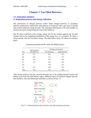
  • 1. Med Phys 4R06/6R03 Radioisotopes and Radiation Methodology 3-1 Chapter 3 Gas Filled Detectors 3.1. Ionization chamber A. Ionization process and charge collection The interactions of charged particles (either direct charged particles or secondary particles produced by interactions with photons or neutrons) with a gas lead to ionized and excited molecules along the path. The important information is the total number of electron-ion pairs created along the track of the radiation. The W-value is defined as the average energy lost by the incident particle per ion pair formed. Due to the competing mechanism of the energy loss, i.e. excitation, W-value is always greater than the ionization energy. The table below shows W-values for common gases. Ionization potential and W-values for different gases. After being created in the gas, electron-ion pairs are in the random thermal motion and diffuse away from the high density region. Different types of collisions happen between free electrons, ions and neutral gas molecules as shown in Fig. 3.1. + + Charge transfer - Electron attachment e- Recombination e- + + - Fig. 3.1. Collisions between free electrons, ions and neutral gas molecules.
  • 2. Med Phys 4R06/6R03 Radioisotopes and Radiation Methodology 3-2 Charge transfer occurs when a positive ion encounters a neutral molecule. In this case, an electron is transferred from the neutral molecule to the ion. When a free electron meets a gas molecule that attaches electrons easily, a negative ion is formed. Oxygen is a good example. Thus, free electrons diffusing in air are rapidly converted to negative ions. In contrast, nitrogen, hydrogen and noble gases have low electron attachment coefficients, and make electrons continuously migrate. To collect electron-ion pairs produced in a gas-filled detector, an electric field must be applied. If the electric field inside the detector is strong enough that recombination becomes negligible, all the charges are efficiently collected without loss. The steady state current measured at this condition is called ionization current, which is the basic principle of the DC ion chamber. I V Fig. 3.2. Basic component of an ion chamber and the voltage-current characteristics. B. Operation of DC ion chambers When an ion chamber is operated in direct current mode, the negative charges can be collected either as free electrons or as negative ions. Thus, any filling gas could be used. Air is the most common filling gas. Typical ionization currents in most applications are very small (1 pA or less). Thus, the leakage current through the insulator can perturb measuring the ionization current. Fig. 3.3. Ion chamber employing guard ring. For example, if we want to keep the leakage current at 1 % level of an ionization current of 1 pA for an applied voltage of 100 V, the insulator should have a resistance of 1016 ohms. Moreover, moisture or surface contaminants can make additional troubles. Practically, a guard ring is employed to reduce this insulator leakage in low current applications of ion chambers. As shown in Fig. 3.3, the insulator is segmented into two parts. Most of the
  • 3. Med Phys 4R06/6R03 Radioisotopes and Radiation Methodology 3-3 applied voltage appears across the outer insulator, for which the resultant leakage current does not contribute to the measured current I. The magnitude of the ionization current is too small to be measured using standard galvanometer techniques. An electrometer, i.e. highly sensitive electronic voltmeter, indirectly measures the current by sensing the voltage drop across a series resistance (109 ~ 1012 ohms) as shown in Fig. 3.4. Provided the ion current does not change for several values of the time constant RC, its steady state value is given by I = VR/R. Fig. 3.4. Low current measurement with a DC electrometer. C. Exposure and dose measurements One of the most important applications of ion chambers is gamma-ray exposure measurement. Exposure is defined as the amount of ionization charge per unit mass of air. An air-filled ion chamber is best for exposure measuring. Fig. 3.5. The principle of compensation and the free-air ionization chamber. Exposure is defined in terms of the ionization created by all the secondary electrons generated at the point at which it is measured. Thus, we need to follow each secondary electron and measure all the ionization created along the track, which would be impractical. Instead, the principle of compensation is used. As shown in Fig. 3.5, if the surrounding region of the test volume is subject to the same exposure, all the charge created outside the test volume from secondary electrons that were produced within the volume is balanced by charge created within the test volume from secondary electrons formed in the surrounding air.
  • 4. Med Phys 4R06/6R03 Radioisotopes and Radiation Methodology 3-4 One design, the free-air ionization chamber, based on the principle of compensation is shown in the figure. Only the volume defined by the central electrode collects ionization current. Compensation is not required in the vertical direction, but takes place in the horizontal direction. Free-air ionization chamber is limited up to ~ 100 keV photons. At higher energies the free-air concept is impractical due to the larger ranges of the secondary electrons and a cavity chamber is used instead. The wall material must be air equivalent and the thickness should be thicker than the secondary electron ranges so that charged particle equilibrium is satisfied. Fig. 3.6 shows typical responses of portable ion chambers use for exposure monitoring. The responses are relatively constant and stable above 50 keV, so ion chambers for exposure measurements are excellent devices. Similarly, ion chambers can be applied to dose measurements as well. For dose measurements, detector materials must be tissue-equivalent to simulate energy absorption of human tissue as closely as possible. Tissue-equivalent plastic is used for the detector wall material while tissue-equivalent propane or methane is used for the gas. Fig. 3.6. Energy responses of ion chamber surveymeters. Fig. 3.7. Principle of gridded ion chambers. D. Pulse mode operation Ion chambers are mostly operated in current mode as described in the section C. If knowledge of the energy deposited by each individual interaction of radiation is required ion chambers can be operated in pulse mode as well. The application of pulse mode ion chambers is limited, but still important in specialized applications like fast neutron spectrometry. The gridded ion chamber is usually used for pulse mode as shown in Fig. 3.7. The ion chamber is divided into two parts by a Frisch grid. The grid has a mesh shape and its potential is intermediate between the anode and the cathode. When electrons start drifting toward the grid, neither electron drift nor ion drift induces any signal voltage, which is measured across the load resistor R. Once the electrons pass through the grid, the signal voltage begins to develop. In this way, the dependence of the signal amplitude on position of interaction in ion chambers can be removed.
  • 5. Med Phys 4R06/6R03 Radioisotopes and Radiation Methodology 3-5 3.2. Proportional Counter A. Gas multiplication Although ion chambers are feasible for pulse mode operation, the signal amplitude is extremely small. For example, when a 1 MeV charged particle deposits all its energy within the chamber, the number of ion pairs produced is 2.86104 for a W-value of 35 eV/ion pair. The capacitance of a typical detector, 10-10 F, leads to the pulse amplitude of 46 V, which requires a sophisticated low-noise preamplifier and pulse processing electronics. If the incident radiation is fast electron or gamma-ray beam, then the pulse amplitude is even smaller. Definitely, if the initial signal amplitude can be made much bigger, the pulse processing becomes much easier. Proportional Counters and Geiger-Müller (G-M) Counters produce a large voltage pulse because the numbers of ion pairs produced are greatly amplified, by the phenomenon known as GAS MULTIPLICATION. Gas multiplication is induced by a strong applied electric field. e- + + + E-field Fig. 3.8. Principle of multiplication process. Fig. 3.9. Variation of  as a function of the electric field. After creation by radiation interaction, both electrons and ions make many collisions with neutral gas molecules until collected. When the electric field is strong enough, electrons get high kinetic energies between collisions and eventually can ionize neutral molecules as illustrated in Fig. 3.8 while ions have low mobility and they attain very little energy between collisions. The two electrons can then be accelerated and further ionizations can be caused. The process takes the form of a cascade (Townsend avalanche). The electric field must be stronger than the threshold. The fractional increase in the number of electrons per unit path length is governed by the Townsend Equation: dx x N x dN e e  ) ( ) (  where Ne(x) = number of electrons for the path length x. The constant  is called the first Townsend coefficient for the gas. Fig. 3.9 shows the dependence of  on the electric field. For a spatially constant field, such as parallel plates,  is a constant, which leads to: Electric field strength α Threshold
  • 6. Med Phys 4R06/6R03 Radioisotopes and Radiation Methodology 3-6 x e e e x N x N  ) 0 ( ) (   The number of electrons increases exponentially with distance. The total number of electrons can therefore be multiplied by a factor of thousands and this amplified signal at the anode is much easier to detect. The charge pulse has a much better signal to noise ratio and this reduces the requirements on external amplifiers. Depending on the electric field strength, operation of gas-filled detectors can be divided into three regions as shown in Fig. 3.10. Fig. 3.10. Operation regions of gas-filled detectors. Proportional region: In this region of applied voltage, the counter is above the threshold for gas multiplication. The multiplication is linear; the collected charge is proportional to the number of ion pairs created by the incident radiation. The pulse is dependent on the radiation type, but, importantly, it is dependent on the incident radiation energy. Therefore, (at fixed applied voltage) measured pulse amplitude (or height)  incident particle energy Limited proportional region: The increase in the applied voltage results in non-linear effects. The free electrons are quickly collected due to high mobility while positive ions are slowly moving, which takes a long time. During the collection of the electrons an (almost) motionless cloud of positive ions is created which is slow to disperse. If the positive ion concentration is high, the electric field is distorted, which leads to distortion in gas multiplication, and non- linearities are observed. The Geiger Müller region: The applied voltage is made sufficiently high that positive ion clouds, the induced positive charge distribution dominates the history of the pulse. The avalanche proceeds until so many positive ions are created that they reduce the electric field below the point at which the gas multiplication can take place. The pulse terminates when the same total numbers of positive ions are created, regardless of the number of initial ions
  • 7. Med Phys 4R06/6R03 Radioisotopes and Radiation Methodology 3-7 created by the incident radiation. Each pulse is of the same amplitude. Thus, the pulse amplitude does not reflect the energy absorbed by the detector by each interaction !! Geiger Müller pulses contain no energy information, no particle information. B. Design of proportional counters The basic cylindrical geometry with a central anode wire and the outer walls acting as the cathode is a very common design for proportional and Geiger-Müller counters. Fig. 3.11. Basic elements of a proportional counter. The polarity is important, the electrons must be attracted to the central axial wire. There are two main reasons why the cylindrical geometry is used with this polarity. The first main reason is that this design allows for practical gas multiplication. Gas multiplication only occurs when the applied electric field is high because the electrons must be accelerated to high kinetic energy. In a parallel plate geometry the electric field is uniform between the plates. If the gap between the plates = 1.0 cm, then to create an applied field of 5.18106 V/m, it is necessary to apply 51,800 V !!! Such a high voltage is practically impossible. In a cylindrical geometry with the anode at the center, the electric field at radius r from the anode is given by E r V r b a ( ) ln( )  where V = the applied voltage, a = anode wire radius, b = cathode tube inner radius. Large values of E are obtained when r is small i.e. near the anode. In a cylindrical proportional counter with a = 80 m, b = 1 cm, to obtain a field E = 5.18106 V/m at anode wire surface, i.e. r = 80 m, V should be 2,000 V, which is conveniently attainable. The second main reason that cylindrical geometries are used in this polarity is to obtain uniform gas multiplication. In a cylindrical counter, uniform multiplication is only achieved if the region of gas multiplication is confined to a very small volume of the gas compared with the total gas volume because the E-field varies rapidly with r and pulse amplitude is in proportion to the E-field.
  • 8. Med Phys 4R06/6R03 Radioisotopes and Radiation Methodology 3-8 Counters are set up so that multiplication only occurs in a small region, this is achieved because gas multiplication has a threshold in the electric field. Using the previous example, suppose that the threshold is 106 V/m: from E r V r b a ( ) ln( )  with a = 80 m, b = 1.0 cm, V = 2,000 V then E > 106 V/m when r < 410 m, which is 0.17% of the counter volume. Therefore, the cascade occurs in the same region regardless of where the original ion pair was formed. The avalanche is therefore confined to a small length region as well. Fig. 3. 12 shows the multiplication process simulated with Monte Carlo calculation. Fig. 3.12. Orthogonal views of an avalanche triggered by a single electron (Monte Carlo simulation). The multiplication process in a cylindrical counter will be: An interaction occurs in the detector  the ion pairs are formed  electrons drift towards anode  electrons reach gas multiplication region  cascade occurs. Sealed tubes Structural rigidity is an issue. The cathode is the outer tube and it must be strong enough to contain the gas and maintain its shape. The cathode is therefore required to have a certain thickness. High energy -rays and neutrons can pass through the walls, but the thickness can mean that low energy -rays, x-rays and charged particles cannot enter the counter. Therefore, an entrance window has to be provided for weakly-penetrating radiations. Gas multiplication requires migration of free electrons, therefore the gas must not absorb electrons. Air (specifically oxygen) is not a good fill gas as negative oxygen ions can be
  • 9. Med Phys 4R06/6R03 Radioisotopes and Radiation Methodology 3-9 easily formed. The counter must not only be rigid but airtight. Sealed counters are practical but often have a limited lifetime because of microscopic cracks in the counter. Fig. 3. 13. Example of a sealed tube counter. Anodes Sample holder Gas in Gas out Fig. 3. 14. A 4 gas flow proportional counter. Continuous flow proportional counters Instead of sealed counters, continuous flow proportional counters can be used. In these counters the gas is circulated and purified to remove impurities or continuously vented. The 4 -ray counter and the thin end window proportional counter used in the electron transport laboratory are both of continuos flow counters where the gas is vented. Fill gases A problem with some fill gases is that photons can be created by gas de-excitation. Gas multiplication is based on secondary ionization. In addition, however, collisions may occur where the gas molecule is raised to an excited state but not ionized, so secondary electrons are not created. There is no contribution of this molecule to the avalanche; it decays by photon emission. The photons can create ionization elsewhere in the fill gas by interacting with less tightly bound electrons or interacting by the photoelectric effect in the counter wall. In proportional counters this creates spurious pulses and/or loss of proportionality. To reduce this effect QUENCH gases are added. These are polyatomic gases that will preferentially absorb the photons. Often this quench gas is methane. The type of fill gas used is dependent on the function the counter is to perform. Commonly used gases for  measurements are the noble gases. These often require a quench gas however. Cost dictates that argon is commonly used, usually as a mixture of 90% argon with 10% methane. This is called P-10 gas. For better -ray detection the fill gas is switched to krypton or xenon. Anode wire variations We know that the electric field depends on the anode wire radius, E r V r b a ( ) ln( ) 
  • 10. Med Phys 4R06/6R03 Radioisotopes and Radiation Methodology 3-10 For large electric fields, r is required to be small, therefore ‘a’ needs to be small i.e. the anode wires have to be thin. However, E(r) will vary with changes in ‘a’, so E(r) will not be constant along a length if ‘a’ varies. It is easier to make uniform wires if they are thicker, but small radii are desired. Practically, compromises have to be made because of the cost of manufacture of uniform thin wires. Gas multiplication factor Total charge Q generated by N0 original ion pairs: Q = N0eM Where M is the average multiplication factor. Diethorn equation: ] ln ) / ln( [ln 2 ln ) / ln( ) ( ) ( ln ) ( ) ( K a b Pa V V a b V d d dr dr r M c c r a r a               Where a: anode radius, b: cathode radius, E: electric field, V: applied voltage, P: gas pressure, V: potential difference through which an electron moves between successive ionization events, K: E/p value at the threshold of the multiplication. Diethorn parameters for proportional gases. Fig. 3.15. Pulse height spectrum and counting curve. C. Counting curve and applications Counting curve plateau Alpha particle: Range in the counter gas is less than the dimension of the detector  Particle energy can be fully absorbed. Beta particle: Range in the counter gas exceeds the dimension of the detector  A fraction of the particle energy is absorbed; Signal pulse is much smaller than those of alpha particles.
  • 11. Med Phys 4R06/6R03 Radioisotopes and Radiation Methodology 3-11 Tissue Equivalent Proportional Counter (TEPC) [2] Microdosimetry aims to measure or calculate a dosimetric spectrum from a microscopic (cellular or sub-cellular) volume of tissue. The energy deposition pattern in this small scale strongly depends on the quality of radiation. The significance of microdosimetry becomes greater in mixed radiation fields such as a neutron-gamma ray field since different linear energy transfer (LET) components can be separated and each dose spectrum can be accurately obtained with a single detector. Xm Em Xg (1/2") Eg Gas cavity Tissue-equivalent material (2 m) Fig. 3.16. Microscopic tissue size simulation with a gas cavity and a typical spherical TEPC geometry. Among various types of radiation detectors, the tissue-equivalent proportional counter (TEPC) has been recognized as best due to its excellent adaptabilities for two fundamental requirements, tissue-equivalence and capability of simulating a microscopic tissue size. A standard TEPC detector is shown in Fig. 3.16. The diameter of the detector is ½ inch and the detector is normally filled with tissue-equivalent gas to simulate 1 or 2 m tissue size. A commonly used tissue equivalent mixtures are tissue-equivalent propane and tissue-equivalent methane. Fig. 3.17 shows an example of a microdosimetric spectrum measured at the McMaster Tandetron accelerator [3]. 10 -1 10 0 10 1 10 2 10 3 0 1x10 5 2x10 5 Total Gamma-ray Neutron Lineal energy, y [keV/m] yN(y) Fig. 3.17. A microdosimetric spectrum measured at the McMaster Tandetron accelerator [3].
  • 12. Med Phys 4R06/6R03 Radioisotopes and Radiation Methodology 3-12 D. Gas Electron Multiplier (GEM) – new class of proportional counter There has been great progress in proportional counter development, especially for wireless detectors. The most successful type of the new detectors is the Gas Electron Multiplier (GEM) [4-6]. The structure and the corresponding electric field lines are shown in Figs. 3.18 and 19. A thin insulating sheet (~ 50 m thick) is coated with a 5 m thick copper layer on both sides. When a high voltage (~ 500 V) is applied, a strong electric field is formed inside the holes (70 m dia.), which leads to the multiplication process. Since the detector structure itself is pixelized, GEM is an attractive way to build a position sensitive gas detector. Fig. 3.18. GEM structure (hole dia.: 70 m). Fig. 3.19. E-filed and equipotential lines in GEM holes. 3.3. Geiger-Müller counter A. Geiger discharge Fig. 3.20. Geiger discharge mechanism. The excited gas molecules produced during a Townsend avalanche in addition to the secondary ions return to the ground state by emitting photons, which plays an important role in the Geiger discharge. The energy of photons is in the visible or ultraviolet region. The photon can be absorbed either by another gas molecule or by the cathode wall through photoelectric effect, which creates another free electron. This new electron is accelerated by the electric field inside the detector and triggers another avalanche. The chain reaction of the avalanche leads to the Geiger discharge. In a Geiger discharge, the rapid propagation of the chain reaction forms many avalanches throughout the
  • 13. Med Phys 4R06/6R03 Radioisotopes and Radiation Methodology 3-13 multiplying region that surrounds the anode. Therefore, the discharge grows to envelope the entire anode wire. The condition required for the chain reaction is Np  1 where, n: number of excited molecules formed in an avalanche, p: probability of photoelectric absorption In the case of a proportional counter, Np << 1 (“subcritical”) and creation of free electrons through photon absorptions is actively suppressed using an additive. The termination of a Geiger discharge is induced by the positive ions. The mobility of the positive ions is much less than that of the electrons, and they remain motionless during the free electron collection time. As the concentration of the positive ions increases near the anode, the space charge effect reduces the strength of the electric field and eventually terminates the discharge. Since the termination condition requires a fixed amount of positive charge, the discharge chain continues until it meets the termination condition regardless of the initial number of electron-ion pairs, which were created through interaction with the incident radiation. Therefore, all output pulses of a G-M counter have the same amplitude, which makes a G-M counter unsuitable for radiation spectroscopy. When positive ions arrive at the cathode, they are neutralized by combining with electrons from the cathode surface, and an amount of energy equal to the ionization energy of the gas minus the work function of the cathode, the energy required to extract the electron from the cathode, is liberated. If this energy is bigger than the cathode work function, another free electron can emerge from the cathode and the free electron triggers another avalanche, leading to a second Geiger discharge. To prevent this multiple pulsing problem, a quenching gas is added to the primary fill gas. The ionization energy of the quench gas is smaller and the molecular structure is more complex (usually, ethyl alcohol and ethyl formate). When positive ions of the primary gas collide with the neutral quench gas molecules, the positive charge is transferred to the quench gas (in fact, an electron is transferred to the positive charge). Then all the ions arriving at the cathode will be those of the quench gas and after neutralization, the excess energy is preferentially used for disassociation of the complex molecules. The requirements for primary filling gases are same as those for proportional counters. The noble gases are widely used as the principal component. B. Geiger plateau If the threshold (or lower level discriminator) of the counting system is Hd as shown in Fig. 3.21, no pulses are counted at 1 kV while all the pulses are counted at 1.2 kV. Accordingly, a big transition occurs in a short interval of the high voltage bias, which is indicated as Knee. If the bias is increased too much the plateau abruptly ends due to the
  • 14. Med Phys 4R06/6R03 Radioisotopes and Radiation Methodology 3-14 start of the continuous discharge. The plateau has a finite slope rather than an ideal flat pattern because the low energy tail is usually present in the pulse height spectrum. Fig. 3.21. Counting plateau for a G-M tube. The block diagram of a counting system for a G-M counter is shown in Fig. 3.22. Because no preamplifier is required, the counting system is simplest. The parallel combination of the load resistance R and the capacitance of the detector Cs (including associated wiring) give the time constant (2 ~ 3 s) of the charge collection circuit. Thus, only the fast-rising component of the pulse is preserved. The coupling capacitor Cc blocks the high voltage, but transmits the signal at ground potential. Fig. 3.22. Electronics for counting pulses from a G-M tube. C. Counting efficiency
  • 15. Med Phys 4R06/6R03 Radioisotopes and Radiation Methodology 3-15 Fig. 3.23. Primary gamma-ray detection mechanism in a G-M tube. Fig. 3.24. Efficiency of a G-M tube for photons. For charged particles, the counting efficiency for any charged particle entered the active volume is 100 % because a single ion pair can trigger a full Geiger discharge. The actual efficiency depends on the probability that the charged particle penetrates the window of the tube. For gamma-rays, most of interactions occur in the wall rather than in the gas. The efficiency is governed by two separate factors: 1) the probability that the gamma-rays have an interaction with the wall material and produce a secondary electron, and 2) the electron gets out of the wall to the fill gas. The principle is described in Fig. 3.23. Fig. 3.25. Energy responses of G-M surveymeters. X- and -ray survey meters normally use G-M counter. The counting rate meter of a survey meter is calibrated with the exposure rate of a known field. The energy dependent response of a G-M survey meter is much less satisfactory than that for the ion chamber. Its popularity arises from the simplicity of instrumentation required due to the large signal output. This makes the device inexpensive and reliable. As shown in Fig. 3.25, the
  • 16. Med Phys 4R06/6R03 Radioisotopes and Radiation Methodology 3-16 response, which is defined as the measured exposure divided by the real exposure, dramatically changes for photon energies below several hundred keV. Either overestimation or underestimation by a factor of 3 is common. This is unavoidable because a G-M counter simply counts the number of events regardless of the energy deposited by the incident radiation. References 1. G.F. Knoll, Radiation Detection and Measurement - 3rd edition (Chapters 16 to 18), John Wiley & Sons, 1999. 2. A.J. Waker, Radiat. Prot. Dosim. 61 (1995) 297. 3. S.H. Byun et al., Phys. Med. Biol. 52 (2007) 1693 4. F. Sauli, Nucl. Instr. Meth A 386 (1997) 531. 5. F. Sauli, Nucl. Instr. Meth A 505 (2003) 195. 6. F. Sauli, Nucl. Instr. Meth A 522 (2004) 93