2. Earth-Science Reviews 216 (2021) 103586
2
(Wang et al., 2018b). Glennie (1970) observed that desiccation crack
pattern could be preserved after formation if sediments filled the spaces.
If layers of soil continue to build up, a historical record of desiccation
cracks can then be preserved underground. Understanding the condi
tions necessary for the formation of desiccation cracking patterns shed
light on the potential correlation between underground water activity
and debatable climatic conditions. Style et al. (2011) pointed out the
possibility of quantifying local windblown (aeolian) sediment levels
based on soil desiccation cracking patterns. The formation of desiccation
cracks dramatically increases the surface roughness of soil, reduces the
wind speed threshold at which sediment particles are picked up from the
soil surface, and thus facilitates sediment entrainment. Researchers have
also compared the desiccation-induced soil polygons on Earth and the
polygonal cracking patterns on Mars, to analyze the historic climate and
mineralogical conditions on Mars and provide possible evidence of
ancient playa settings (El Maarry et al., 2012; El-Maarry et al., 2013,
2014). Moreover, desiccation cracks considerably modify the hydrologic
flow path conditions, increase the weathering of soils, and impair their
water retention capabilities, resulting in the aggravation of soil erosion
and the destruction of local environmental ecology (Zeng et al., 2020).
In engineering field, soil is an important geological material that can
be applied in various earth structures. The ensuing formation of desic
cation cracking networks negatively alter soil properties and compro
mise the integrity of soil structures (Morris et al., 1992; Chaduvula et al.,
2017). The presence of isolated or coalesced cracks in near-surface soils
causes severe degradation to their hydraulic and mechanical properties,
the dominant factor to many potential geotechnical hazards as shown in
Fig. 2. Crack networks considerably modify the soil structure and impact
its hydraulic behavior by creating preferential flow paths for fluids and
contaminant transport (Chertkov and Ravina, 1999; Chertkov, 2000;
Horgan and Young, 2000; Kalkan, 2009; Tang et al., 2011b; Cheng et al.,
2020a, 2020b). Mechanical properties of soils subjected to desiccation
cracking are also significantly degraded, resulting in weakened strength,
excessive deformation, and increased compressibility (Morris et al.,
1992; Albrecht and Benson, 2001; Tang et al., 2011c). The combined
effects are responsible for the reduced performance or even ultimate
failure of infrastructure foundations and earth structures.
In recent years, the more frequent occurrence of extreme weather
and climate change at the global scale aggravate the crucial desiccation
cracking issues (Robinson and Vahedifard, 2016). Understanding the
List of symbols
a,b,c,k1,k2,k3,k4,k5,k6 Soil parameters
A, Ac Total surface area of the soil specimen and total crack area
B Crack thickness
c′
, capp Effective cohesion and apparent cohesion of unsaturated
soils
ce Conversion factor
C Crack driving force
CL Crack line density
da The amount of crack growth
D Energy dissipation rate
Dfrac Fractal dimension of crack edge and crack area
Diff, Diffa Hydraulic diffusivity and hydraulic diffusivity at air-dry
water content
e Evaporation flux density
F Surface flux
ha Relative humidity of the air
hb Bubbling pressure
H Inverse of the relative humidity at the soil surface
Ld The side dimension of the box in image analysis
Lv Latent heat of vaporization
Nbox The number of boxes needed to cover the entire image in
image analysis
Nc The number of crack segments
Nn Number of crack nodes
Nseg Surface crack number
qsat The saturation specific humidity
Qn All net radiation at the soil surface
rs Dimensionless geometrical factor
rsurf Surfaced resistance
rv Boundary layer resistance to vapor transport
Re Evaporation rate
Rsc Surface crack ratio
s Soil suction
Sr, Src, Sr,res, Sr
e
Degree of saturation, critical degree of saturation at
which the tensile strength reaches a maximum value,
residual degree of saturation and normalized or effective
degree of saturation
S0 Matric suction at ground surface
Ta, Ts Air temperature and surface temperature
U, USE potential energy and surface energy
ua Pore air pressure
V1,V2 Soil volume before and after shrinkage
W Groundwater depth
w, wc,wopt Water content, cracking water content, optimum moisture
content
wel, wpl Elastic energy and plastic energy
Wavg, Wsum Average crack width and total crack width
Z1,Z2 Soil thickness before and after shrinkage
Zc Depth of cracks
Zcf*, Zcfi* Water table depth and initial water table depth
Greek symbols
α Soil parameter related to soil microstructure
αc Crack geometrical parameter
αPSD Soil pore-size distribution Parameter
αvg, nvg Fitting parameters of van Genuchten’s SWCC model
βG Soil parameter
Γ Energy needed to change the soil fabric
γ Unit weight of soil
γ0 Specific surface energy
δij The Kronecker delta
△CR, △Z Crack volume change and soil Thickness change
ζ Soil parameter
θ, θ*
,θa, θi, θr, θs Volumetric water content, critical volumetric water
content, air-dry volumetric water content, initial
volumetric water content, residual volumetric water
content and saturated volumetric water content
κ Soil parameter related to plasticity index
λ1, λ2 Volume average thermal conductivity of zone 1 & 2
υ Poisson’s ratio
ρva, ρvss Atmospheric vapor density and vapor density at soil
surface
σt, σt
′
, σt, opt, σt, sat
′
, σtr, σtu Tensile strength of compacted clayey
soils, effective tensile strength, tensile strength at optimum
moisture content, effective saturated tensile strength,
residual tensile strength at fully saturated condition and
uniaxial tensile strength of unsaturated sands
σ0, σc Fracture driving force and fracture resisting force
σ, σs
, σij
′
, σij Total normal stress, suction stress, effective stress tensor
and total stress tensor
Φ Slope of the saturation vapor pressure versus temperature
curve at the mean temperature of the air
C.-S. Tang et al.
3. Earth-Science Reviews 216 (2021) 103586
3
effects of desiccation cracking on soils is essential in dealing with
associated geological, geotechnical and geoenvironmental engineering
problems. Moreover, the concept of desiccation cracking is of great
importance in many other engineering and science disciplines, such as
transportation engineering, structural engineering, mining engineering,
environmental engineering, agricultural engineering, food engineering,
material engineering, and planetary sciences (Table 1).
Desiccation cracking is a complex phenomenon involving the
coupled interaction of soil and atmosphere (Cui et al., 2013). Over
recent decades, substantial research efforts have been devoted to
developing experimental, theoretical and numerical approaches to
investigate the fundamental cracking mechanism and characterizing the
cracking behavior of soils. Several review papers have been published in
the past on this topic: Morris et al. (1992) reviews the occurrence and
morphology of cracks in the dry-climate regions, and developed theo
retical solutions to capture the crack depths observed in the field; Péron
et al. (2009c) described the physical processes associated with the
desiccation cracking of soils and discussed the initiation and propaga
tion of desiccation cracks; and Kodikara and Costa (2013) presents a
summary of historical field observations, laboratory modeling and
identified mechanisms. Bordoloi et al. (2020) provided an insight into
the influence of vegetation on soil cracking in the context of the soil-
water-plant interaction. Wei et al. (2020) summarized part of experi
mental work and mechanism study of desiccation cracking behavior.
Comprehensive state-of-the-art reviews emphasizing lab- and field-scale
investigation approaches, cracking dynamics, and influencing factors of
desiccation cracking behaviors remain unavailable.
This review updates previous review papers, builds upon researches
developed in the past few decades, and covers most key research aspects
associated with soil desiccation cracking, including experimental and
modeling approaches, underlying mechanisms of multi-physics, multi-
scale deformation and cracking, and various intrinsic and external
influencing factors. All literatures (including more than 400 references)
available to the authors concerning this topic were extensively
reviewed. The structure of this review is arranged as follows: Section 2
summarizes the past and existing experimental methods that have been
invented and adopted for soil desiccation cracking analyses at both
laboratory and field scales. Section 3 discusses various theoretical
frameworks formulated to account for the underlying cracking
mechanisms. Section 4 shows how mesh-based and mesh-free numerical
models are configured to capture the initiation, propagation, and coa
lescence of desiccation cracks. Section 5 describes the crack dynamics in
desiccating soil, with emphases placed on the coupled process of water
evaporation, suction increase, volume shrinkage, and the crack network
evolution. Section 6 categorizes major influencing factors of desiccation
cracking in soils into four groups covering soil intrinsic properties,
boundary constraints, environmental conditions, and soil admixtures.
Finally, Section 7 provides a brief summary of existing developments
and suggests directions for prospective research works.
2. Experimental investigation of desiccation cracking
As summarized in Table 2, numerous experimental methods have
been applied to monitor, capture, and characterize the desiccation
cracking process in soils since the early 20th century (Kindle, 1917).
Various parameters have been used to describe the extent of cracking,
with typical geometrical descriptors of the crack morphology detailed in
Section 2.3. Analyzing results obtained from these methods provides a
qualitative and quantitative description of the dynamic cracking process
and the evolving crack pattern. Some methods are suitable for both lab-
scale and field-scale, whereas others are limited to a narrower scale. In
comparison, applications at field scale generally result in a lower-
resolution characterization of the cracking features. Different methods
focus on different sets of descriptors of the crack network, ranging from
2D to 3D and from local to global scales.
2.1. Laboratory tests
2.1.1. Specimen preparation
Specimen preparation process during desiccation cracking tests
considerably impact the accuracy and repeatability of experimental re
sults. The most common types of specimens used in laboratory tests are
in slurry or compacted state.
Slurry specimen is a popular choice for laboratory testing, because of
its easy preparation, relatively homogeneous state, and procedure
repeatability (Goehring et al., 2010; Tang et al., 2011a; DeCarlo and
Shokri, 2014b). Desiccation tests in a laboratory are generally carried
out under simple but controlled environment, to minimize the
Fig. 1. Desiccation cracking phenomenon in nature soil.
C.-S. Tang et al.
4. Earth-Science Reviews 216 (2021) 103586
4
disturbance of environmental factors. A typical preparation of a slurry
specimen comprises the following steps: The original soil specimen is
dried, crushed, and sieved first, before pre-weighed amount of water is
added to those fine soil particles and mixed to reach the homogenous
slurry state. To ensure the full saturation of specimens and allow com
plete dispersion of soil particles, initial target water content should be
sufficient and close to about 1.5 times of the liquid limit (Tang et al.,
2016b). Several techniques are available to remove entrapped air bub
bles. Compared to the carefully tapping of the mold or the vacuum-based
air removal method, the vibration technique that vibrates the specimen
on a shake table for 2–15 min is more effective in desiccation tests
(Péron et al., 2009b; Tang et al., 2010a, 2012). The sample will be
tightly sealed and deposited for 24–72 h to ensure sufficient sedimen
tation (Tang et al., 2011c).
Some desiccation cracking tests of soils have been carried out on
compacted specimens, following the standard Proctor compaction pro
cedure (Harianto et al., 2008) or the modified Proctor effort (Albrecht
and Benson, 2001), but possibly prepared in different shapes or sizes
(Nahlawi and Kodikara, 2006; Krisdani et al., 2008; Lakshmikantha
et al., 2012). The crushed and dried soil particles are mixed with specific
water amount before compaction to reach the target initial water con
tent and dry density.
During the specimen preparation process, the grain size distribution
needs to be well controlled because of its strong influence on the
desiccation cracking process. Higher percentage of coarser particles
(>0.002 mm) in clay may cause larger surface crack areas (Yesiller et al.,
2000). The interplay of particle size, soil structure and plasticity in
fluences the desiccation cracking behavior of soils (Tang et al., 2008).
Considering a single factor whereas ignoring the other two may result in
inaccurate prediction of soil shrinkage and cracking characteristics.
To mitigate the negative influence of volumetric shrinkage and
desiccation cracking on soil engineering performance and improve soil
strength and resistance, researchers have investigated the potential of
soil reinforcement using additives in both field and laboratory scale
tests, such as lime (Omidi et al., 1996a), silica fume (Kalkan, 2009),
cement (George, 1971), sand (Tay et al., 2001), and fiber (Abdi et al.,
2008; Harianto et al., 2008; Tang et al., 2012; Tang et al., 2016a).
Homogenously mixing soils and admixtures is the key to these studies,
because of the strong dependency of cracking pattern on microstructural
anisotropy and inhomogeneity (Stavridakis et al., 2006). The recent
development using bio-mediated methods such as microbial induced
calcite precipitation (MICP) has been applied to remediate desiccation
cracks in soils (Guo et al., 2018b; Vail et al., 2019a). However, due to the
low permeability of clay, laboratory preparation of soil samples requires
using the pre-mixing (Guo et al., 2018b; Vail et al., 2019a) or surface
spraying method (Liu et al., 2020a, 2020b).
2.1.2. Experimental apparatus
Laboratory apparatus used for the investigation of soil desiccation
cracking can be categorized into two major groups according to their
functionalities: (1) The controlling of environmental conditions, typi
cally using an environmental chamber equipped with various sensors
(Tang, 2008; Cui et al., 2014; Shokri et al., 2015; Lakshmikantha et al.,
2018; Tran et al., 2019a; Liu et al., 2020a, 2020b) and (2) The moni
toring and capturing of key parameters of the cracking process, based on
tools such as image acquisition system, laser scan device, X-ray
computed tomography scanner, and distributed fiber optics (Table 2).
Soil microstructural features such as particle size distribution, pore
networks and inter-granular contacts are generally characterized by
microscope, scanned electron microscopy (SEM), or Mercury Intrusion
Porosimetry (MIP) (Romero and Simms, 2008; Monroy et al., 2010; Wei,
2014). SEM also enables the observation of nano- and micro-cracks that
are not visible by digital camera and the study of local mineralogy and
heterogeneities. These techniques provide micro- and nano-scale views
of cracks and soil structures, but are rarely used directly for larger-scale
crack characterization. Different scales of cracks from centimeter to
kilometer are founded by field observation.
Laboratory study of desiccation cracking in soil requires precise
control of environmental variables, such as temperature, relative hu
midity, light intensity, and air circulation. To improve the repeatability
and reliability of experimental results, some researchers (Amarasiri
et al., 2011; Lakshmikantha et al., 2018; Tran et al., 2019a; Liu et al.,
2020a, 2020b) conducted soil desiccation tests using environmental
chamber to investigate the response of soil cracking behavior under
various temperatures and relative humidity conditions. However,
because of the complicated setup process and high cost of environment
chamber, researchers often resort to the temperature-controlled oven,
which is less expensive and able to provide a constant temperature
condition in the range of 20–110 degree Celsius (Rayhani et al., 2007;
Tang, 2008; Tang et al., 2010a). A fan is sometimes used to mimic
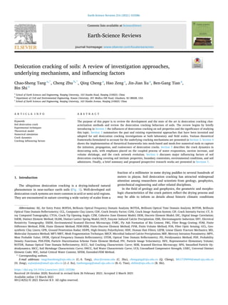
Fig. 2. Drought-induced soil desiccation cracking and potentially associated geo-hazards.
C.-S. Tang et al.
5. Earth-Science Reviews 216 (2021) 103586
5
natural wind condition above Earth’s surface and to facilitate the water
evaporation under given conditions (Harianto et al., 2008).
Research efforts have been made using several monitoring and
characterization tools to capture desiccation cracking networks. An
effective and low-cost approach is through an image acquisition setup,
comprising digital camera, supporting frame, and light source (Tang
et al., 2008). Samples are often placed on a digital scale to allow the
simultaneous and real-time monitoring of the water loss during desic
cation. Fig. 3 illustrates a typical laboratory set up for the continual
measurement of water loss and detection of crack development during
desiccation cracking test (Miller et al., 1998; Lakshmikantha et al., 2009;
Tang et al., 2010a; Tran et al., 2019a). Sometimes, air flow fans and
water spraying systems are installed to simulate wind action and rainfall
conditions, respectively (Miller et al., 1998). Camera is among the most
commonly used tools for crack imaging in the laboratory and field, as
images provide a spatiotemporal record of crack formation pattern. The
post-processing speed is correlated with the resolution of the image,
with high-resolution corresponding to high computational costs. To
address this concern and acquire the most appropriate image results for
highly efficient processing, three major techniques are recommended
(Tang, 2008). First, the suggested camera resolution falls within the
range of 5 to 10 million pixels (Tollenaar et al., 2017). Lower number of
pixels impairs the image quality and lowers the results’ accuracy,
whereas higher number of pixels substantially increases the required
processing time. Second, using single light source could improve the
light condition above the soil specimen surface, but may be easily
influenced by weather, timing, and multiple light sources in the labo
ratory. To ensure sufficient and consistent light intensity, it is recom
mended to place the specimen completely under the shadow of another
object or inside a closed environment with one light source only (Tang,
2008). Both solutions have been validated for capturing high quality
desiccation cracking images. Third, the camera setup should be fixed
throughout the test, with the focusing direction orthogonal to the soil
surface at a fixed magnification level (Shokri et al., 2015). For soil crack
patterns obtained under bad photographing condition (such as uneven
illumination, field environment or poor photographing angle), Xu et al.
(2020) proposes a novel automatic soil cracks recognition method based
on deep learning and fount that this method presents satisfactory per
formance in soil crack image recognition and quantification.
Despite that digital camera provides a cost-effective way for crack
Table 1
The influences of desiccation cracking on various disciplines.
Discipline Area Influences of desiccation cracking Reference
Earth science Surface soil Morphological features of surface soil cracks provide implications to the
study of sedimentation conditions, sediment constituents, and paleoclimate
conditions. Desiccation cracks also influence the transport of surface
materials from Earth’s crust.
(Glennie, 1970; Style et al., 2011; Wang et al., 2018b)
Geotechnical
engineering
Slope Cracking at the crest area of the slopes triggers the initiation of slope failure. (Take, 2003)
Embankment Desiccation cracks provide potential erosion pathways to embankments,
resulting in possible piping failures.
(Foster et al., 2000)
Dam Cracks may lead to dam failure. The increase in hydraulic conductivity of
soils can facilitate water infiltration and reduce the soil shear strength.
Moreover, cracks can form part of a slip surface that has no shear strength.
(Talbot and Deal, 1993; Xu and Zhang, 2009; Peng and
Zhang, 2012)
Foundation High temperature leads to considerable volume shrinkage to the clay layer.
Shrinking cracks usually pass via several buildings and roads over large
areas, causing significant bearing capacity and settlement issues.
(Silvestri et al., 1992; Yilmaz et al., 2014)
Pipeline Water and gas pipelines buried in expansive soils are affected by the shrink
and cracking behavior of soils.
(Rajeev and Kodikara, 2011)
Geo-environmental
engineering
Clay liner Desiccation cracking causes damage to the soil liner integrity and induce
leakage of fluids from burial sites.
(Kleppe and Olson, 1985; Boardman and Daniel, 1996;
Omidi et al., 1996b; Miller et al., 1998; Tay et al., 2001;
Li et al., 2011)
Nuclear waste
disposal
Bentonite buffer zones can undergo thermal drying, shrinkage and cracking
near the waste canister.
(Park and Kim, 2001; Davy et al., 2007; Gourc et al.,
2010)
Structural
engineering
Earthen heritage Rain-saturated earthen wall surface can form flowing slurry and become
cracked surface crusts under intense desiccation, which may be easily peeled
off by wind deflation.
(Zhang et al., 2016)
Transportation
engineering
Subgrade Reactive soil induced cracking in road bases is a major problem and inure
substantial annual maintenance costs worldwide.
(Lytton et al., 1976; Chakrabarti et al., 2001)
Highway
shoulder
Cracks developed in the paved highway shoulders due to differential
heaving and shrinking of underlying and adjacent soils, inducing intrusion
of surface water runoff into underlying soil layers.
(Intharasombat et al., 2007)
Mining engineering Mine tailing The drying rates and stability of mine tailings are influenced by the cracking
process and the resulting permeability changes. The potential pollutant
generation on infiltration may cause environmental consequences.
(Morris et al., 1992; Rodríguez et al., 2007)
Food engineering Dried noodle Inappropriate drying conditions can result in decreased production
efficiency, undesirable deformation, and the formation of cracks, consisting
of discontinuities within the dried noodle.
(Inazu et al., 2005)
Agricultural
engineering
Tillage Fracture of soils is important consideration in tillage and water and chemical
usage in agricultural engineering.
(Ahmad and Mermut, 1996; Kelly and Pomes, 1998;
Chertkov, 2002)
Material Engineering Coating process Cracking and warping (or curling) cause problems in many coating and
material elaboration processes that are based on the drying of colloidal
suspensions.
(Pauchard et al., 1999)
Concrete Limiting the formation of plastic shrinkage cracks is critical to lengthen the
service life of concrete structures.
(Morris and Dux, 2006)
Gel and colloid Many coating and material elaboration processes are based on the drying of
colloidal suspensions, in which cracking and warping should be avoided.
(Pauchard et al., 1999; Scherer, 1999; Lee and Routh,
2004)
Planetary sciences Mars Desiccation cracks form giant polygons on Earth and Mars, and provides
evidence of presence of water.
(El Maarry et al., 2010, 2012; El-Maarry et al., 2013,
2014, 2015a, 2015b, 2015c; Stein et al., 2018)
Asteroids Desiccation cracking is potentially capable of generating dust and ejecting it
from the surface of asteroid.
(Cloud Jr., 1968; Jewitt et al., 2013)
Modified from Kodikara and Costa (2013).
C.-S. Tang et al.
6. Earth-Science Reviews 216 (2021) 103586
6
Table 2
State of the Art: experimental methods developed to quantify desiccation crack morphology of soils.
Characterization method Specimen dimension
• (L*W*D) (lab/field)
• diameter*thickness (lab)
• L*W (field)
Characterization parameter References
Camera (lab and field) 1.5 m * 1.0 m * 0.5 m (field) Crack intensity factor (Miller et al., 1998)
400 mm * 7 mm * 5 mm (lab) Number of cracks, crack width, separation between cracks (Lecocq and Vandewalle,
2002)
24 cm * 30 cm * 5 mm (lab) Minkowski numbers, Minkowski functions, angles of bifurcation (Vogel et al., 2005b)
160 mm *160 mm * 5 mm (lab) Number of crack segments and intersections, total/average crack length,
average crack width, number of clods, average area of clods, surface crack
ratio, probability density functions (PDF), fractal dimension
(Tang et al., 2007b)
2.44 m * 2.44 m * 1.22 m (field) Crack area, fractal dimension, crack area mass fractal dimension (Baer et al., 2009)
1189–297 mm * 841–210 mm *
10–20 mm (field)
Surface shrinkage, total crack area, average area of cells, total crack length,
average crack width, length of crack per unit area
(Lakshmikantha et al.,
2009)
295 mm * 49 mm * 12 mm (lab)
295 mm * 15 mm * 15 mm
(lab)
Number of cracks, crack-spacing, crack opening, intercepting angle (Péron et al., 2009b)
16 cm * 16 cm * 8 mm
(lab)
117 mm * 2.5–5 mm (lab)
Surface crack ratio, crack intersection angle, number of intersection, number
of crack segment, average length of crack, average width of crack, average
area of aggregates, crack intensity factor, probability distribution of crack
length
(Tang et al., 2008, 2011a,
2011b; Liu et al., 2013)
100 mm * 5 mm (lab) Crack intensity factor, density of length of fissure (Trabelsi et al., 2012)
80 mm * 80 mm * 3–20 mm (lab) Tensile strain (Costa et al., 2013)
180 mm * 210 mm (field)
525 mm * 820 mm (field)
Crack porosity, crack aperture, crack density, density of crack polygon,
spatial distribution of crack, crack orientation
(Li and Zhang, 2010, 2011)
430 mm * 430 mm * 25 mm (lab) Crack velocity, crack angle, crack width distribution, crack length and
density, fractal dimension of the crack network, correlation function of crack
area
(DeCarlo and Shokri,
2014a)
9.689 cm * 1.292 cm (lab) Area of gap, area of crack, area of settlement (Sánchez et al., 2013)
Laser device (lab) 7.2 cm * 10.8 cm (lab) Crack aperture, crack porosity, specific surface area (Gebrenegus et al., 2011)
9.689 cm * 1.292 cm (lab) Surface elevation, crack depth, crack area, soil volume (Sánchez et al., 2013)
80 mm * 40 mm (lab) crack specific parameters (depth, length, width, and volume) (Uday and Singh, 2013a)
X-ray Computed
Tomography (lab)
40.5 mm * 40.5 mm * 56 mm (lab) Crack fraction, dead and branch number, crack depth, maximum crack
velocity, specific volume
(DeCarlo and Shokri,
2014b)
12 cm * 12 cm (lab) crack aperture distributions, crack porosities, and crack specific surface
areas
(Gebrenegus et al., 2011)
7.54 cm * 2 cm (lab) crack area, crack width, crack depth and crack intersection angles (Julina and Thyagaraj,
2019)
50 mm * 100 mm (lab) Soil mass area, shrinkage ratio, crack ratio, average crack width, total crack
length, number of crack segment
(Tang et al., 2019)
Ground penetration radar
(field)
1300 mm * 650 mm (field) Electrical anisotropy (Greve et al., 2010)
Electrical resistivity
tomography (lab and
field)
180 mm *180 mm * 30 mm (lab) Apparent electrical resistivity (An et al., 2020)
29 cm * 3 cm * 2 cm (lab) Apparent electrical resistivity (Tang et al., 2018)
2.4 dm * 1.7 dm * 1.6 dm (lab) Apparent electrical resistivity (Samouelian et al., 2003)
100 m * 6 m (field) 2D and 3D apparent electrical resistivity field (Jones et al., 2014)
49.5 cm * 49.5 cm * 17.5 cm (lab) 3D apparent electrical resistivity (Jones et al., 2012)
Petri dish of 10 cm diameter (lab) Electric field (Tarafdar and Dutta, 2019)
Fiber-optical sensing (lab
and field)
200 cm * 9 cm * 7 cm (lab) Surface crack ratio (Li and Zhang, 2010)
250 mm * 25 mm * 18 mm (lab) Strain, drying rate (Costa et al., 2018)
Digital Image Correlation
(lab)
117 mm * 117 mm * 8 mm (lab) Strain field (Wang et al., 2018b)
5.5 cm * 4 cm (lab) Volume strain, local strain (Peth et al., 2010)
Particle image velocimetry
(lab)
Restrained ring (dout-ring = 133 mm;
dinner-ring = 40 mm)
Strain field (Shannon et al., 2015)
Scanning Electron
Microscopy (lab)
20 mm * 20 mm * 20 mm Crack network (Fauchille et al., 2014)
12 cm* 0.5 cm Local particle alignment (Mal et al., 2008)
4 mm * 4 mm * 2 mm Water sensitivity, crack type, clay mineral proportion, dominant clay family (Montes et al., 2004)
150 mm * 3 mm Micro crack, salt precipitation pattern (Shokri et al., 2015)
600 μm * 600 μm * 2/5/10 nm
300 μm * 300 μm * 2/5/10 nm
100 μm * 100 μm * 2/5/10 nm
crack spacing, crack density, crack length (Seghir and Arscott, 2015)
Field observation Tens of meters wide and up to 300 m
wide polygons
Large desiccation polygons in playas in California, USA (Neal et al., 1968)
Kilometer-scale Giant cracks on Mars (McGill and Hills, 1992;
Pechmann, 1980)
1–30 m wide Image obtained from the imaging spectrometer orbiting Mars (El-Maarry et al., 2015a,
2015b, 2015c)
A series of distinctive centimeter-
scale reticulate ridges on Mars
Maximum width; vertex angles (Stein et al., 2018)
C.-S. Tang et al.
7. Earth-Science Reviews 216 (2021) 103586
7
monitoring, such image acquisition apparatus is only suitable for the
two-dimensional characterization of surficial cracks, and incapable of
providing cracking information across the specimen depth or soil surface
roughness features. More advanced systems involving multi-component
(camera) setups will be required to increase measurement accuracy
(Brossard et al., 2009), which however requires complex setup and post-
processing of the data collected from different systems. Comparatively,
the non-contact laser scanner, comprising compact two- or three-
dimensional scanner, laser motion controller, and data acquisition sys
tem, has been developed and applied for profiling the cracked soil sur
face (Fig. 2) (Sánchez et al., 2013; Hirmas et al., 2016). During scanning,
laser lines are generated by special lenses, projected on the soil surface,
and diffusely reflected back to a highly sensitive sensor matrix through
the projection of a high-quality optical system (Sánchez et al., 2013).
The motion controller coupled to the scanner precisely controls the scan
speed and moves perpendicular to the laser line, covering the entire
surface area of the specimen. The soil profiles represented by an array of
points are processed by computer software for further analysis. This
technique is more advantageous as it permits 3D representation of the
soil specimen based on the compilation of subsequent 2D linear profile
data and geometrical analysis of evolving morphology of the crack
network (Sánchez et al., 2013; Sánchez et al., 2014; Zielinski et al.,
2014). A similar approach based on laser optical microscopy has been
developed to enable 3D imaging and measurement of cracks (Uday and
Singh, 2013a). Although the laser scan technique provides some insights
into the 3D cracking development, the intrinsic feature of surface
reflection limits its ability of detecting crack initiation and evolution
inside the soil body.
Based on images recorded before and after displacement, the digital
image correlation (DIC) technique yields continuous full-strain mea
surement on soil sample surfaces (Chu et al., 1985). The strain field
analyses based on DIC are able to show that desiccation cracks belong to
mode I and stress redistributes around them, which cause the orthogonal
intersecting of neighboring cracks (Wang et al., 2018b). DIC has also
been used to study the deformation and fracture evolution of clay-rock
under desiccation and heating (Hedan et al., 2012; Wang et al., 2015).
Particle image velocimetry (PIV) enables acquiring high-definition
velocity fields around structures for the reconstruction of the hydro
mechanical loading (Zhang et al., 2019a). PIV has been applied to study
crack initiation during the flexure of a clay beam (Thusyanthan et al.,
2007). The PIV analysis essentially involves analyzing the pixel move
ment between pictures with respect to target textural properties of the
surface. PIV software has the ability to produce displacement vector
fields related to the soil movement (Costa et al., 2008), which is sig
nificant to the improved understanding of the crack evolution (Lin et al.,
2019).
In laboratory tests, some cracks appear on the top surface of soil
specimen, whereas others are located within the specimen and not
directly visible from outside (Lakshmikantha et al., 2009, 2012). These
invisible cracks include primary cracks that originate at the bottom
boundary or within the sample and secondary cracks that propagate
from primary cracks within the soil body (Levatti et al., 2017). To detect
non-visible cracks and investigate the three-dimensional cracking pro
cess, researchers have resorted to other sophisticated techniques, such as
electrical resistivity tomography (ERT) and X-ray computed tomography
(CT).
The electrical resistivity of soil quantifies how anions and cations
move under applied electrical field, which is a sensitive reflection of
many soil properties (Archie, 1942; Keller and Frischknecht, 1966;
Arulanandan and Muraleetharan, 1988; Gibert et al., 2006; Andrews
et al., 2012; Chambers et al., 2012; Chambers et al., 2014; Gunn et al.,
2015; Kaufhold et al., 2015), including: (1) solid features: mineralogy,
shape, fabric, and size distribution; (2) void arrangement: porosity,
tortuosity, connectivity, pore structure; and (3) fluid properties: water
content, electrical resistivity, solute concentration. Therefore, the
continual, nondestructive and sensitive method based on ERT is suitable
for crack characterization at both laboratory and field scales. Through
the determination of the electrical resistivity distribution of the sur
rounding soil volume, this method evaluates the spatial and temporal
variations of soil physical and mechanical properties, such as soil
composition (Zhou et al., 2015), structural characteristics (Klein and
Santamarina, 2003), water content (Sheets and Hendrickx, 1995), and
compressibility (Ghorbani et al., 2013). The presence of cracks signifi
cantly alters the flow paths of the electrical current field due to the
extremely low electrical conductivity of air (approximately ten orders of
magnitude lower than soil), causing great potential losses than it would
be experienced in intact soils (Samouelian et al., 2004, 2005) (Fig. 4).
Therefore, ERT is effective to capture the development of desiccation
cracks, reliable to map the cracks’ positions (Fig. 5), and even predict
the early formation of cracks (Fig. 6) (Gong et al., 2009; Greve et al.,
2012; Jones et al., 2012; Hassan and Toll, 2013; Tang et al., 2018; An
et al., 2020). Samouëlian et al. (Samouelian et al., 2003) first confirmed
the capability of electrical resistivity method in identifying artificially
created cracks in a silty loam, with high resistivity area representing the
crack and lower resistivity area representing intact soil. Similar re
searches were conducted by Sentenac and Zielinski (2009). Jones et al.
(2012) used the electrical resistivity method to map desiccation crack
networks in compacted clays under laboratory conditions. A comparison
of Schlumberger, Dipole–Dipole and combined arrays for visualizing the
cracks visualization was presented, indicating that the combined
method produced the most accurate image of the damaged subsurface.
This is consistent with the findings concluded by Friedel et al. (2006)
that a combination of Wenner–, Schlumberger– and Dipole–Dipole data
provided a reasonable compromise between measurement time and
image resolution. The typical image resolution of electrical method
applied to soil desiccation crack monitoring in laboratory can reach the
centimeter level (Samouelian et al., 2003). Soil crack can be considered
as insulation, and their equivalent resistivity is much greater than that of
soil, which enables the electrical method to yield good monitoring re
sults (An et al., 2020). Moreover, the typical image resolution of the
electrical method can be improved by controlling the electrode layout
density, electrode device, and electrode-soil contact (Binley et al., 1996;
Athanasiou et al., 2007; Jones et al., 2012; Tang et al., 2018).
Comparing with other three-dimensional characterization tech
niques such as laser scan and electrical resistivity tomography discussed
earlier, X-ray CT is an effective and nondestructive technique that allows
high-resolution visualization of the internal structure of objects (Mees
et al., 2003). Emitted X-ray beams penetrate the object along multiple
directions. The measurement of progressive attenuation reflects the
density contrast of the object (Phillips and Lannutti, 1997). The elec
tronics engineer G. N. Hounsfield from EMI company designed and set
up the first computed tomography scanner in 1972. The CT technique
was first introduced to the field of medical radiology (Hounsfield, 1973)
and then widely applied to study other materials. In the field of soil
science and geology, Petrovic et al. (1982) conducted a pioneering CT-
based study and revealed the linear relationship between soil bulk
density and X-ray attenuation. Since then, many research efforts have
been made to apply X-ray CT in characterizing geological materials.
Researchers first examined the correlation between X-ray energy level
and the relative attenuation of X-ray passing through soil minerals
(Carlson et al., 2000; Van Geet et al., 2000). The significant difference
between attenuated X-ray passing through soil pores and soil solids
enables the application of X-ray CT in the quantification of porous soil
microstructure. X-ray CT-based research is capable of studying the
volumetric and geometrical characteristics of the pore and crack net
works in soil, such as porosity (Anderson et al., 1990), pore diameter
(Peyton et al., 1992), perimeter and area (Grevers et al., 1989), circu
larity (Gantzer and Anderson, 2002), and crack network density (Perret
et al., 1999). Cracks initiate, propagate and coalesce in soil during
various physical processes, resulting in a complicated cracking network.
The imaging features of X-ray CT technique enable qualitative de
scriptions of 3D crack networks (Fig. 7), which provides new insights
C.-S. Tang et al.
8. Earth-Science Reviews 216 (2021) 103586
8
into the integrated qualitative and quantitative investigations of soil
microstructural changes and underlying failure mechanisms (Julina and
Thyagaraj, 2019; Tang et al., 2019; Zhao and Santamarina, 2020). The
integration of X-ray CT and mechanical tests such as triaxial compres
sion or bending tests further enables the real-time investigation of dy
namic deformation and structure damage process in soils (Otani et al.,
2000; Mukunoki et al., 2014).
2.1.3. Limitations of laboratory tests
Many laboratory tests have been carried out under room conditions,
with a relatively good control of specimen features (e.g., initial state,
specimen size, thickness, mineral composition), environmental vari
ables (e.g., temperature, humidity, dry-wet cycle, soil-container inter
face), and the configuration and operation costs. To improve the
fundamental understanding of how cracks evolve under drying condi
tions, several major experimental methods have been developed at
laboratory scale to measure the amount of water evaporation (Table 3).
However, most experimental tests at laboratory scale are limited to a
specimen size of less than 500 mm (Table 2), which exhibits strong
boundary effects and may impair the reliability of experimental results
(Konrad and Ayad, 1997). To bridge the gap between small samples
tested under laboratory conditions and the responses of soils at field
scale, larger-scale containers or environmental chambers have been
proposed as an alternative solution for testing (Cui et al., 2014; Cordero
et al., 2016). But it should be noted that environmental conditions such
as temperature and relative humidity are not perfectly constant and
difficult to control due to the technical limitation of the climate chamber
(Péron et al., 2009b), which may impose some instabilities to the soil
desiccation process.
As described above, a large number of laboratory-scale character
izations of desiccation cracking process in soils are conducted through
camera, laser scan, and CT scan, which are not appropriate to be
extended to field scale measurements (Table 2). Moreover, current
experimental apparatus for desiccation testing are configured tempo
rarily according to specific experimental tasks. Such setup is usually
susceptible to environmental and boundary influences and thus may
produce less repeatable results, which highlights the importance to
develop integrated reliable experimental apparatus to automatically
record water content, matrix suction, crack morphology and environ
mental variables.
2.2. In-situ tests
2.2.1. Visual inspection
In-situ desiccation cracking tests remove the boundary limitations
encountered in laboratory tests, and expose soil sections to real natural
environment. Because of the relatively higher cost of operation, more
input of sample preparation and testing time and efforts, and less pre
dictable and varying environmental conditions, only a few field studies
on soil desiccation tests have been reported so far, which have been
reviewed in this study.
In the past, visual inspections of soil cracks in the field mostly resort
to two major approaches: (1) Direct observations of soil surface,
requiring the surveyor to walk alone the entire earth structures (e.g.,
embankment and slope) for crack surveying and measurement (Kleppe
and Olson, 1985; Dasog and Shashidhara, 1993); and (2) destructive
techniques such as the excavation of trenches to observe the crack
propagation depth (Dyer et al., 2009). Konrad and Ayad (1997) carried
out desiccation study of clay by excavating test sites to three different
depths, including top soil layer, weathered clay crust, and intact clay.
During a continual 35-day drying, they observed and recorded the crack
initiation and formation process in different layers and measured
evaporation, consolidation, suction change and relative humidity
change on soil surfaces, in order to explain the cracking mechanism. The
cracks initiated after 17 h of drying with an average spacing of 20–24
cm, much larger compared with those observed in laboratory-scale tests.
Weinberger (1999) investigated the formation of desiccation cracks in a
muddy sediment at the foot of Massada, Dead Sea region, Israel. This
study addresses the location, propagation direction, and fracture
mechanisms of mud cracks and their surface morphology. Some cracks
were found to nucleate at or near the bottom of the polygons and
propagate vertically upwards and laterally outwards. Their study also
reveals the fundamental role of local stress concentration, layer
boundaries, and soil constituents in mud fracturing.
Baer et al. (2009) chose a clay soil site in Missouri State for field
testing. They constructed two 2.44 m by 2.44 m by 1.22 m (depth)
testing pits, covered the pit with rain-proof shelters, and installed sen
sors to measure the soil moisture content (Fig. 8). Before the test, testing
pits were filled with water to reach the saturation state. An access tube
was installed to a depth of 1.50 m in the buffer zone of each rainout
shelter to monitor soil water content by neutron attenuation. Soil
particle-size was determination by the pipette method. The camera
installed 1.52 m above the soil captured the soil cracking process. They
analyzed the fractal dimension of crack edge and crack mass area, and
found out that the higher smectite content increased the crack area and
fractal dimension of crack area, but had less influence on the fractal
dimension of crack edge.
Li and Zhang (2010, 2011) carried out a two-year field study to gain
insight into the mechanism of desiccation crack development in soil.
Camera
Soil specimen
Scale
Fig. 3. Schematic view of a typical test setup that uses a camera for
crack monitoring.
Scale
Soil sample
Slide way
Laser scanner
Laser
Data acquisition
pad for motion
controller
Computer
Scale
Soil sample
Slide way
Laser scanner
Laser
Data acquisition
pad for motion
controller
Computer
Fig. 4. Soil desiccation cracking test device based on laser scanning technique.
Modified from Sánchez et al. (2013).
C.-S. Tang et al.
9. Earth-Science Reviews 216 (2021) 103586
9
Their results indicate that the crack pattern is closely related to the
water content and drying time. The three-stage crack development in
the field is difference from those observed from laboratory tests as the
boundary restraints are removed. They also concluded that the Repre
sentative Elementary Volume (REV) for the cracked soil was approxi
mately five times the mean crack length, above which the dependence of
crack porosity on domain size was negligible.
Manual measurement is the main approach adopted for crack anal
ysis during visual inspection. Dasog et al. (1988) measured crack size by
using a 2-m tape placed at random locations in the field for multiple
times. El Abedine and Robinson (1971) obtained the crack length by
counting the intersections of the caliper and cracks. Ringrose-Voase and
Sanidad (1996) devised a tool comprising 6 connected half-circles to
quickly quantify the crack numbers. These techniques are operator-
dependent, causing significant inaccuracy to the measured geometrical
parameters.
Visual inspection technique provides a direct view of desiccation
cracking network in soils. However, under certain circumstances,
desiccation cracks can be obscured by surface covering materials such as
dense vegetation (Dyer et al., 2007; Tang et al., 2018), making it difficult
for accurate cracking surveying. Although the actual depth and the
development of subsurface cracks can be identified by the excavation of
trenches, this destructive technique is time-consuming, laborious, and
may considerably destroy the integrity and reduce the stability of the
earth structure. Moreover, the original crack pattern could be easily
disturbed by human activities and equipment when those traditional
methods are employed. Varying environmental conditions add to the
challenge of accurate visual inspection of cracks in the field and may
induce the overestimation or underestimation of cracking in soils during
drying and wetting seasons, respectively (Jones et al., 2014).
2.2.2. Geophysical survey
The quantitative in-situ inspection and subsequent analysis of
desiccation cracks provide insights into the evolution of crack networks
and soil clods. To overcome the limitations encountered during visual
inspection, various geophysical inspection methods such as fiber optics,
ground penetration radar (GPR), electrical resistivity tomography (ERT)
and electromagnetic induction (EMI) have been developed.
In the 1980s, the progress made in fiber-optic communication led to
the rapid development of fiber optic sensors. These sensors have been
widely applied in numerous civil and geological engineering projects,
attributed to their strong resistance to corrosion and electromagnetic
interference, great electrical insulation, high adaptability, and low en
ergy loss for long-distance measurements (Merzbacher et al., 1996).
Several fiber optic sensing (FOS) technologies have been developed for
monitoring civil infrastructures, such as fiber Bragg grating (FBG), op
tical time domain reflectometry (OTDR), optical frequency domain
reflectometry (OFDR), Raman optical time domain reflectometry
(ROTDR), Brillouin optical time domain reflectometry (BOTDR), Bril
louin optical time domain analysis (BOTDA), and Brillouin optical
V
A
V
A
C1 P1 P2 C2 C1 P1 P2 C2
Crack
)
b
(
)
a
(
Fig. 5. Schematic view of current flow in the four-electrode configuration during electrical resistivity measurement: (a) intact soil; (b) cracked soil.
1 cm
)
b
(
)
a
(
Fig. 6. Mapping of desiccation cracks using the electrical resistivity tomography method: (a) soil crack image; (b) electrical resistivity image.
C.-S. Tang et al.
10. Earth-Science Reviews 216 (2021) 103586
10
frequency domain analysis (BOFDA). Among all FOS technologies, FBG
and BOTDR are the most classical and widely-used techniques (Zhu
et al., 2017), developed as a continuous and real-time strain measure
ment method for various engineering applications, such as ground
displacement (Klar and Linker, 2010), tunnel structure (Mohamad et al.,
2011), bridge (Zhang et al., 2006), beam (Zhang et al., 2007), pavement
(Weng et al., 2015), foundation (Piao et al., 2008; Wei et al., 2009), and
slope (Zhu et al., 2013b; Zhu et al., 2014). Fig. 9 shows the principle and
set up of the BOTDA technique. The existing application of fiber optics in
soil deformation and cracking analysis is still tentative and limited to
laboratory scale (Cheng et al., 2020a, 2020b) (Fig. 10). Wang et al.
(2009) applied the BOTDR technique for the monitoring of soil slopes at
the laboratory scale. Their results highlighted the potential of using
BOTDR for measuring the abnormal deformation of soil slope. Zhang
et al. (2012) performed a one-dimensional laboratory test and used FBG
strain sensors to capture the entire process of soil shrinkage and cracking
due to dehydration. Their results showed the strain change in soil before
the onset of cracking, implying the possibility of using FOS for early-
crack detection in soils. Recent developments in FOS have further
reduced the fiber diameter and the cost of production and improved the
measurement accuracy, which makes FOS a more suitable tool for in-situ
soil cracking and deformation measurement. The study by Liu et al.
(2018) introduces a large-scale (> 200 m length) subgrade cracking
monitoring study based on the BOTDR technique and demonstrated its
high accuracy in crack location identification and size quantification.
The high resolution of OFDR up to 1 mm provides a promising option for
desiccation cracking characterization.
Ground penetration radar (GPR) is a non-destructive and indirect
technique that uses electromagnetic pulses to detect reflecting surfaces
inside the soil allowing the mapping of soil stratigraphy. Soils with
different electromagnetic properties lead to different reflections of
electromagnetic waves from boundaries (Annan, 2009). Due to its
sensitivity to soil structure changes (e.g., void, discontinuity, strati
graphic surface), GPR has been applied in multiple geotechnical engi
neering areas, with the main focuses placed on soil water content
estimation (Huisman et al., 2003; Slater et al., 2009; Klotzsche et al.,
Fig. 7. Three-dimensional reconstruction of the soil specimen during desiccation when water content is at: (a) 42.5%; (b) 37.3%; (c) 36.4%; (d) 34.1%; (e) 29.2%; (f)
25.0%; (g) 15.6% (Tang et al., 2019).
Table 3
Summary of laboratory experiment methods to measure water evaporation in soils.
Category Methodology Principle Use conditions and pros/cons References
“Weight
difference”
test
Evaporation pan The amount of water evaporated can be determined
by monitoring the weight change of the evaporation
pan and the evaporation rate can be determined
according to the change of water level.
It is mainly used to study the soil evaporation of soil
with sufficient water supply and evaporation of free
water surface. The measurement results are greatly
influenced by the structure and size of the device.
(Kondo et al., 1992;
Wilson et al., 1994)
Soil column
(box)
The amount of water evaporated can be determined
by monitoring the weight change of the soil column.
The measured parameter is unitary. It is difficult to
carried out large scale soil column evaporation test
due to the precision of the weight measuring device.
(Kondo et al., 1990;
Kondo et al., 1992; Wilson
et al., 1994; Smits et al.,
2011)
Integrated
evaporation
test
Environmental
chamber
A stable environmental condition is established and
the atmospheric parameters and soil indices are
monitored by the sensors in the environmental
chamber.
The measured parameters are abundant. The
operation cost is relatively low and the test is easy to
operate.
(Mohamed et al., 2000;
Cui et al., 2013; Song
et al., 2013)
Wind tunnel The atmospheric parameters (e.g. wind speed,
radiation, temperature, humidity) are accurately
controlled. The amount of water evaporated at
various environmental conditions is monitored by the
evaporation measuring device.
The atmospheric parameters can be stably
monitored and the amount of water evaporated
during the drying process can be monitored.
However, the cost is relatively high and the
operation is complicated.
(Yamanaka et al., 1997;
Li, 2003)
C.-S. Tang et al.
11. Earth-Science Reviews 216 (2021) 103586
11
2018) and plant roots detection (Hruska et al., 1999; Martinková and
Prax, 2000; Stokes et al., 2002). Despite the strong correlation between
water content and soil shrinkage, the usage of GPR for the detection of
desiccation cracks in soils have not been fully explored yet. GPR was
recently used for small desiccation tests at the laboratory scale (Levatti
et al., 2017). Results indicate GPR is capable of detecting cracks of 1 or 2
mm wide, but unable to detect sub-millimeter cracks. Although limited
in characterizing small cracks, the GPR method is useful to find time-
related bounds of crack initiation and to estimate their locations. In
comparison to FOS, GPR provides a significant amount of data while
allowing the soil surface to remain undisturbed for continuous and
future surveying. However, the surveying results strongly depend on the
choice of data treatment approaches and antenna frequencies (Zajícová
and Chuman, 2019).
Another field-scale crack characterization technique is the electrical
resistivity tomography (ERT), extended from laboratory scale to larger
scale by adjusting the inter-electrode spacing. ERT offers greater flexi
bility in the volume of soil that needs to be investigated and allows the
detection of the scaling properties of a fracture system at different res
olutions (Jones, 1995). At present, most field-scale crack characteriza
tion techniques using ERT are related to slope and embankment
investigations. Friedel et al. (2006) showed that 2D or 3D ERT surveying
results were consistent with drilling and sampling data for the investi
gation of a slope. Khan et al. (2017) carried out ERT tests near the crest,
middle and toe of a shallow slope and highlighted the electrical re
sistivity discontinuity due to the presence of desiccation cracks. The ERT
method was applied for monitoring soil moisture in railway embank
ments (Chambers et al., 2014) and profiling cracked flood embankments
(Sentenac et al., 2013; Jones et al., 2014). The field-scale measurements
were validated through forward modeling, using different crack con
figurations and accounting for the effect of topography. It was concluded
that the ERT method could be used at regional scale to detect zones of
cracking. Researchers have also used the ERT technique to detect the
interior fracture volume change and evaluate the restoration quality of a
building foundation after mortar treatment (Abu-Zeid et al., 2006).
In addition to ERT, the electrical property of soil has been leveraged
in another surveying technique known as the electromagnetic induction
(EMI). EMI uses the correlation between the amplitude and phase of
electromagnetic fields and the electromagnetic features of soils for large-
scale soil survey, particularly effective for frozen soil mapping (Sheets
and Hendrickx, 1995; Jaynes and Robert, 1996; Kneisel et al., 2008).
EMI demonstrated the ability to map salinity and ionic characteristics
(Mcbride et al., 1990; Corwin and Lesch, 2005), clay content (De Ben
edetto et al., 2010), water content (Rhoades et al., 1976; Doolittle and
Brevik, 2014) and soil temperature (Robinson et al., 2009), some of
which are closely related to the shrink-swell potential of soil and imply
that EMI has potential applications in soil crack characterizations,
especially advantageous for permafrost characterization in cold regions
(Barrowes et al., 2019).
2.3. Quantitative characterization of crack morphology
Desiccation cracks in soils usually possess complex network struc
tures, resulting from the response of the soil fabric to drying conditions.
The quantitative characterization of crack morphology improves the
fundamental understanding of the underlying mechanism of soil desic
cation processes. Wopereis et al. (1994) first performed a crack
morphology analysis and pointed out the strong dependence of crack
morphology on the damage extend of plants’ root systems and the
movement of moisture within cracks. Perrier et al. (1995) used the size,
connectivity, and geometrical features of crack network to predict the
future cracking phenomenon in the soil subjected to wet-dry cycles.
Ringrose-Voase and Sanidad (1996) indicated that quantitative analysis
of desiccation cracking network provided a reliable evaluation of the
evolution of structure, density and volume in desiccated soils. In terms
of engineering applications, the geometrical features of cracks such as
width, length, depth, connectivity, and spatial distribution are critical
factors to the performance of infrastructures, especially those built on
soils (Chen, 2012). Establishing correlations between quantitative crack
parameters and soil properties helps remediate desiccation cracking
problems, predict soil performance under future drying, and guide new
constructions in regions of expansive soils.
With the continuing development of computer and image processing
technology, researchers proposed various geometrical parameters for
more quick and accurate characterization of crack morphology. To
quantify the crack network, Corte and Higashi (1960) used the cumu
lative crack length per unit area of soil as the descriptor. Miller et al.
(1998) first introduced the concept of Crack Intensity Factor (CIF) based
on the theory of fracture mechanics, which was defined as the time-
variable ratio between total crack area and total intact soil surface
area. CIF has been adopted by other researchers to describe the extent of
cracking in laboratory soil samples (Tang et al., 2008) and landfill liners
(Yesiller et al., 2000; Miller and Rifai, 2004; Harianto et al., 2008).
Lakshmikantha et al. (2006) pointed out that CIF may cause confusion
due to its similarity with the stress intensity factor. For this reason,
another parameter surface crack ratio (RSC), which is the ratio of the
surface cracks area to the initial total surface area of a specimen, was
proposed to quantify the cracking extent on the soil surface (Tang et al.,
2010a). The soil cracking characteristic curve (SCCC) (RSC versus water
content) can be therefore determined to describe the dynamic process of
camera access hole
soil surface
rainout shelter
(front side removed)
plot area
access tube
subsurface lining
1.52 m
2.44 m
1.22 m
2.44 m
Fig. 8. Schematic view of the soil desiccation test in the field.
Modified from Baer et al. (2009).
Pulsed light
Optical fiber
PPP-BOTDA
Fig. 9. Schematic view of the principle of BOTDA.
C.-S. Tang et al.
12. Earth-Science Reviews 216 (2021) 103586
12
desiccation cracking.
Soil clods make up the other significant component in the desiccated
soil body and reflects the development of the crack network. As the
originally intact soil body is cracked into a number of polygons, the
cracking driving force will decrease, eventually smaller than the tensile
strength of a single clod, which stops the generation of new cracks and
new clods (Horgan and Young, 2000). The largest piece of clod can be
treated as the maximum stable aggregate size, documenting the for
mation and development of desiccation cracks. The aspect ratios of soil
clods, defined as the ratio between primary and secondary axis of their
fitting ellipses, are also used to characterize the crack morphology as
well as the soil polygons (Lakshmikantha et al., 2006).
Such quantitative analyses contribute to the understanding of
desiccation cracking, but generally simplify the description of the
complicated cracking network by using only one or two REV (Repre
sentative Element Volume)-scale indicators. A more comprehensive set
of descriptors is needed to cover various crack features such as crack
width, crack length, crack skeleton, and crack connectivity. Tang et al.
(2008) developed a Crack Image Analysis System (CIAS) in MATLAB to
systematically analyze camera images, extract the crack network skel
eton (Fig. 11), and quantify the geometrical parameters of crack net
works. These geometrical parameters include, but not limited to, surface
crack area, crack number, total and average crack length, total and
average crack width, clod number, average clod area, and the fractal
dimension. Table 4 summarizes a number of geometrical parameters
that have been used by different researchers to describe the crack
morphology. Considering that some detailed crack pattern features may
be overlooked during average- or total-based calculations of geometrical
parameters, probability density function has also been introduced to
statistically describe the fracture network.
Majority of existing investigations on digital image processing of
desiccation cracking pattern rely on commercial graphics software such
as Adobe Photoshop or open-source image processing program such as
ImageJ, which are not specifically targeted for the quantitative analysis
of desiccation cracks and incapable of comprehensive quantitative
analysis of crack patterns. This may cause lower efficiency and less ac
curacy in analyzing complicated crack networks. Implementing user-
defined plugins into ImageJ or executing user-defined functions in
MATLAB and leveraging machine learning or artificial intelligence
techniques are growing trends for the more precise and reliable quan
titative analysis of crack networks (Choudhury and Costa, 2019).
3. Theoretical models for desiccation cracking
To reveal the fundamental mechanisms of desiccation cracking,
assess the potential of cracking under specific conditions, and further
predict the geometric characteristics (especially crack spacing and
depth-to-spacing ratio) of crack networks, researchers have formulated
various theoretical frameworks, which can be categorized into three
major groups, including energy-based model, stress-controlled cracking
model, and volume-based model.
3.1. Energy-based model
Based on the theory of fracture mechanics, Griffith (1924) first
proposed that the damage of material originated from micro-defects and
micro-voids in the material, causing local stress concentrations. The
transition of materials from elastic state to damage state and then
fractured state drives the dissipation of elastic energy. When surface
energy resulting from crack development is in balance with the energy
dissipation due to cracking, cracking occurs (Lima and Grismer, 1994;
Hallett et al., 1995; Hallett and Newson, 2001; Prat et al., 2008). Frac
ture mechanics provides an energy-based interpretation: When the
stiffness of materials with defects decreases, stress intensity induced at
the crack tip causes crack propagation, resulting in macroscopic
cracking network.
3.1.1. Linear elastic fracture mechanics (LEFM) model
Linear elastic fracture mechanics (LEFM) model is a common model
used to predict soil desiccation. Early work on shrinkage-induced
cracking using fracture mechanics was first introduced by Lachen
bruch (1961), who analyzed the crack depth and spacing in basalt and
permafrost using the Griffth’s fracture model based on the theory of
elasticity. Morris et al. (1992) predicted crack depth width using 1-D
analytical solutions. Based on the energy conservation, the decreased
potential energy because of tensile stress is balanced with the increased
surface energy due to the formation of new crack network:
δU ≥ δUSE (1)
in which δU is the decreased potential energy, δUSE is the increased
surface energy.
According to the Griffth’s energy principle, the critical stress is
expressed as:
σ0 = σc (2)
in which σ0 acts as the fracture driving force, and σc is the fracture
resisting force.
LEFM has been extensively applied in investigating desiccation
cracks. Burton et al. (1984) used LEFM to analyze three-dimensional
desiccation cracking processes. Bittencourt et al. (1996) used LEFM to
capture the two-dimensional crack propagation. Based on LEFM, Morris
et al. (1992) predicted the depth of cracks using
Zc =
1.6420S0
S0
W
+ vγ
1− 2v
(3)
in which S0 is the matric suction at ground surface, W is the groundwater
depth, v is the Poisson’s ratio, and γ is the unit weight of soil.
Ayad et al. (1997) applied the LEFM approach to model a field
experiment. However, these models were unable to accurately predict
crack spacing. Fleureau et al. (2015) linked the digital image correlation
(DIC) technique with fracture mechanics to explain the mechanisms of
formation and propagation of cracks, and analyze the strains and dis
placements in the material prior to cracking. In addition to desiccation
cracks, LEFM is also applicable for analyzing the cracking of soil under
tension. Typical problems include tensile cracks along soil slope and
tensile cracks near the utility pole subjected to lateral wind load.
Fig. 10. Correlation between desiccation cracks and strain distribution curves
obtained from optical fibers (by BOTDA).
C.-S. Tang et al.
13. Earth-Science Reviews 216 (2021) 103586
13
The crack network predicted by LEFM provides a reference value for
conservative engineering design and assessment. This method provides
a theoretical basis for future model development and enables reliable
implementations in numerical tools. However, one major disadvantage
of LEFM lies in the fact that soil is not a brittle and linear elastic material,
and the dissipation of energy from other processes such as elastic
mismatch, inter-particle friction, and micro-cracking could be substan
tial (Hallett et al., 1995). These processes result in non-linear fracture
behavior (Vo et al., 2017) and the creation of a process zone where
plastic energy is dissipated (Kendall and Weihs, 1992). Another limita
tion is that LEFM considers the propagation of only one individual crack
and neglects the interaction among multiple cracks. These limitations
primarily contribute to the discrepancy between theoretical predictions
and cracks observed under real situations.
3.1.2. Elastoplastic fracture mechanics
In classical fracture mechanics, the formation of soil cracks is
considered as a thermodynamic equilibrium process. The mechanical
energy applied is equivalent to the energy needed to generate desicca
tion cracks. The change of mechanical energy dU adds to the internal
energy of soil dw, with dU = dw when no crack growth occurs. For a
linear elastic model, the change of soil structure due to mechanical
energy is completely reversible when the load is removed. However,
such assumption ignores the fact that considerable amount of energy
(plastic energy wpl) is dissipated due to the rearrangement of soil par
ticles, the inter-particle friction, and the debonding of inter-particle
bonds (Abu-Hejleh and Znidarčić, 1995). The elastoplastic fracture
mechanics model improves the linearly elastic fracture mechanics model
by considering the plastic process and the irreversible plastic energy
dissipation during desiccation cracking.
In the elastoplastic fracture mechanics model developed by Hallett
and Newson (2005), external energy can be decomposed into two parts,
reversible elastic energy and irreversible plastic energy. When cracks
propagate, sufficient energy change is required to break the inter-
particle bond at the crack tip:
dU = dwel + dwpl + dΓ (4)
in which dΓ = 2Bγ0da is the energy needed to change the soil fabric, a
function of the specific surface energy γ0 and the increase in surface area
due to cracking (evaluated from the amount of crack growth da and the
crack thickness B), wel is recoverable elastic energy, and wpl is irrecov
erable plastic energy.
The energy sink to crack growth is the energy dissipation rate D,
defined as:
D =
d
(
wpl + Γ
)
Bda
(5)
The energy source to crack growth is the crack driving force C,
defined as:
C =
d(U − wel)
Bda
(7)
For fracture to occur, the source and sink must be equal, i.e., C = D.
Fig. 12. illustrates the evolution of cracks using the loading diagram.
Once yield is exceeded, plastic processes further reduce the matric po
tential at the crack tip and causes the build-up of the strain energy at the
tip. Energy is released as crack growth initiates, which corresponds to
the drop in the force applied. Steady-conditions occur once ductile crack
growth becomes stable. J-integral analysis, first introduced by Rice
(1968), can be used to evaluate the energy requirements for the onset of
ductile crack growth in soils (Chandler, 1984). Costa and Kodikara
(2012), Costa et al. (2015) used the J-integral method to evaluate the
elastoplastic fracture behavior of soils during the ring test. As this
technique accounts for the change in elastic potential energy and plastic
potential energy, it is reasonable to use this technique to analyze the
elastic-plastic transition during crack propagation.
However, in reality, it remains challenging to quantify the parame
ters associated with the elastoplastic fracture mechanics model and
distinguish the elastic and plastic processes during soil cracking.
Therefore, most model developments are implemented in numerical
tools for parametric studies or sensitivity analyses, and still need suffi
cient experimental data for validation.
3.2. Stress-controlled cracking model
3.2.1. Tensile failure
Tensile failure is recognized as the most common type of failure for
soil desiccation cracking. The failure criterion is defined in such a way
that, soil cracking occurs when the tensile stress experienced by the soil
exceeds its tensile strength. Therefore, both tensile stress and tensile
strength govern the cracking criterion. Morris et al. (1992) developed
analytical solutions to compute crack depths that represented the posi
tion where local tensile stress reached tensile strength, with suction used
as the state variable for stress analysis. Kodikara and Choi (2006) pre
sented a simplified analytical model for the desiccation cracking of long
layers of soil accounting for basal restraints and tensile failure. Al-
Dakheeli and Bulut (2019) established the relationship between
computed tensile stress and soil suction based on the restrained ring test.
Instead of suction, moisture content has also been used as a governing
state variable for desiccation modeling, with soil media sometimes
considered as non-elastic materials. Other researchers have adopted the
rock mechanics theory and used the Griffith failure criterion to define
soil tensile strength (Senior, 1981).
Various correlations between the tensile strength of soil and its
physical properties have been established. Research results indicate that
tensile strength decreases nonlinearly with the increasing water content
Clod area
Crack length
Crack width
Crack area
Crack intersection
angle
Intersection point
Endpoint
1 cm
Fig. 11. Geometrical descriptors determined from the digital image processing of desiccation crack patterns.
C.-S. Tang et al.
14. Earth-Science Reviews 216 (2021) 103586
14
or decreasing matrix suction (Al-Shayea, 2001; Nahlawi et al., 2004). It
has been shown that macro porosity also exerts a significant effect on
tensile strength (Carter, 1990; Munkholm et al., 2002). Table 5 sum
marizes prediction models that have been developed to predict the
tensile strength of fine-grained compacted soils.
Stress-path based failure criterion has been proposed based on tensile
failure criterion. Abu-Hejleh and Znidarčić (1995) developed a
desiccation theory for the consolidation and desiccation analysis of soft
fine-grained soils. Their theory assumes that soils remain saturated and
homogeneous before reaching shrinkage limit. They decomposed the
consolidation and desiccation process into four segments (Fig. 13): (1)
consolidation under one-dimensional compression (OK and WK), (2)
desiccation under one-dimensional shrinkage (KM and KB), (3) propa
gation of vertical cracks and tensile stress release (MN and BV), and (4)
desiccation under three-dimensional shrinkage (BU and VS). The
concept of total and effective stress paths are used to analyze the overall
consolidation and desiccation process. Desiccation cracks occur when
the lateral stress exceeds its tensile strength under 1D shrinkage (point
M in Fig. 13), expressed as − σh = σt, in which σh is the total lateral stress,
σt is the tensile strength. The stress path model, developed based on the
stress paths of soft clay under desiccation, accounts for the integration of
consolidation, desiccation, and cracking. However, this model assumes
that the soil is homogeneous and remains saturated before reaching
shrinkage limit, which makes this theoretical model unsuitable for
analyzing the desiccation of compacted clay.
In summary, despite its simplicity, mode-I tensile failure-based
mechanistic interpretation neglects the inherent, cohesionless-yet-
frictional, and effective-stress-dependent behavior of soils (Shin and
Santamarina, 2011). Moreover, assumptions that zero effective stress at
the crack tip may not truly reflect the fundamental mechanism at the
particle level.
3.2.2. Shear failure
At the preliminary stage, desiccation cracks generally belong to
mode I failure (Griffith, 1924). When cracks propagate to certain extent,
gravity of the soil at the opposite sides of the crack increases the shear
stress (Fig. 14), which makes the prediction of crack depth using shear
failure criterion (mode II) reasonable.
Morris et al. (1992) decomposed the desiccation cracking process
into two stages governed by tensile failure and shear failure, respec
tively. During the tensile failure stage, the model is assumed linear
elastic. Desiccation cracks generated in this stage are induced by matric
suction and the resulting tensile stress. As crack depth increases, the
gravity stress increases and the matric suction reduces, which jointly
contributes to the more dominant role of shear stress in governing the
soil desiccation cracking. Once the stress state satisfies the shear failure
criterion, desiccation cracks initiate and propagate. Desiccation-induced
crack depth can be estimated as a function of matric suction, tensile
strength, and shear stress. Morris et al. (1992) adopted a graphical
method to find out the crack depth and validated the results through
numerical simulations. Thusyanthan et al. (2007) performed an inves
tigation of the stress and strain criteria for crack initiation in clay using
four points bending test equipped with high capacity tensiometers. In all
tests, the effective stress state measured at the initiation of failure rea
ches the Coulomb failure envelope. Murray and Tarantino (2019) car
ried out direct tensile tests on a series of clay samples prepared at
different initial suction conditions and found that the mechanism of
failure under tensile total stress states can be interpreted in terms of
effectives-stress dependent shear failure criterion.
Based on desiccation tests on double-T-shaped specimens and hydro-
mechanical simulations, Gerard et al. (2018) suggest that non-linear
elastic models with shear failure criterion are able to predict both the
time and the location of desiccation cracking. Their results further
validate the assumption that cracking can be explained by an effectives-
stress-dependent failure criterion, i.e. assuming that crack initiates by
shearing under tensile total stress states.
Shear failure accounts for the influence of the gravity of soil and the
resulting shear stress on the crack stability, which matches well with the
real situation. This model is applicable for the analysis of crack propa
gation along the vertical direction and helps interpret the cracking
process under shear. However, this model does not account for the fact
that tensile strength increases as a result of the increasing gravity stress.
Further investigations are still in need to quantify the influence of these
Table 4
Geometrical parameters defined to characterize crack morphology.
Geometrical parameter Definition Introduced by
Crack intensity factor (CIF),
also known as surface crack
ratio (Rsc), or crack density
factor (CDF)
CIF =
Ac
A
Ac= total crack area; A = the
total surface area of the soil
specimen.
(Miller et al.,
1998)
Crack intersection angle The angle between the
intersecting crack skeletons
(Lakshmikantha
et al., 2009)
Number of crack nodes (Nn) Two types of nodes are
considered: intersection
nodes between crack
segments and end nodes of a
single crack that does not
intersect another crack.
(Liu et al., 2013)
Surface crack number Nseg The crack is defined by two
node adjacent to each other
on the trace line.
(Tang et al., 2008)
Average crack width Wavg
Wavg =
Wsum
Nseg
Wsum= total crack width,
with each width calculated
as the shortest distance from
a randomly chosen point on
one boundary to the opposite
boundary of the crack
segment (Fig. 11).
(Liu et al., 2013)
Average crack length Lavg
Lavg =
Lsum
Nseg
Lsum= total crack length,
with each length calculated
as the trace length of the
medial axis of crack segment
(Fig. 11).
(Liu et al., 2013)
Crack line density CL The ratio between the
perimeters of all cracks and
the total surface area of soil
(Zong et al., 2014)
Width, length, direction, and
number of clod (clod =
independent closed area
that is split by cracks)
Feret diameter is defined as
the orthogonal distance
between a pair of the parallel
tangents to the feature at a
specified angle to the unit.
Clod length = maximum
Feret diameter
Clod width = minimum Feret
diameter
Clod direction = direction of
maximum Feret diameter
(Liu et al., 2013)
Fractal dimension Dfrac of
crack edge and crack area
a measure of the space filling
nature of an image, is
calculated as the negative
slope of the linear regression
of log(Nbox) vs. log(Ld). Nbox
= the number of boxes
needed to cover the entire
image; Ld = the side
dimension of the box.
(Baer et al., 2009)
Probability density function f
of a crack geometrical
parameter αc
f(α) =
∆Nc
Nseg∙∆αc
αc= crack parameter (e.g.,
length, width, area)
∆Nc= the number of crack
segments whose length
ranges between Δl
(Tang et al., 2008)
Most probable value (MPV) MPV = the geometrical
parameter α related to the
maximum value of f(α)
(Tang et al., 2008)
C.-S. Tang et al.
15. Earth-Science Reviews 216 (2021) 103586
15
factors on the stress state evolutions of soils.
3.3. Volume-based model
Volume-based models use the entire soil body as a basis and correlate
the soil volume change indicators (e.g., void ratio) with the formation of
cracks. In these models, soil cracking results from soil volume or void
ratio changes, which contributes to the formulation of various volume-
based theoretical models.
Water content is usually applied to estimate the total volume change.
Combining with the shrinkage of soil volume during water content
changes, volume-based models relate volume change to desiccation
cracking and consolidation deformation. Fredlund and Morgenstern
(1976) first proposed constitutive relations for volume change in un
saturated soils. Bronswijk (1988, 1991) proposed to use water content
and void ratio to determine the soil shrinkage characteristics without
considering detailed mechanics of cracking. The soil thickness change
induced by consolidation and crack volume is related as.
V1 = (Z1)3
, V2 = (Z1)(3− rs)
(Z2)rs
,
V2
V1
=
(
Z2
Z1
)rs
(16)
in which rs is a dimensionless geometrical factor (1D shrinkage: rs =
1; anisotropic shrinkage: rs = 3), V1 and V2 are the soil volume before
and after shrinkage, respectively. Z1 and Z2 are the soil thickness before
and after shrinkage.
∆Z = Z1 −
(
V2
V1
)
1
rs Z1 (17)
∆CR = (V1 − V2) − Z2
1(Z1 − Z2) (18)
in which △CR is the crack volume change, and △Z is the soil thickness
change. This model uses the shrinkage characteristics to determine the
soil volume change and derive the crack volume and soil thickness
change based on rs.
Researchers have carried out investigations to study the empirical
constant rs and volume changes during the soil desiccation process. Fox
(1964) concluded that the geometrical factor of wet soil was dominated
by one-dimensional consolidation. By carrying out field-scale shrinkage
study of soils under loading effects, Talsma (1977) correlated rs with
water content, rather than loading. Hallaire et al. (1984) concluded that
wet soil volume change was merely a result of the generation of cracks.
Trabelsi et al. (2012) related cohesion not only to suction but also to
porosity, in order to model shrinkage phenomenon followed by crack
development in soils. The shrinkage characteristics curves made by
Chertkov (2007, 2008) indicates that crack volume is negligible when
soil sample is small enough. Stewart et al. (2016) formulated a theo
retical model to characterize the void distribution at different stages of
soil shrinkage. This model used water content as the input parameter
and reflected the characteristics of soil shrinkage, consolidation, and
desiccation cracking through the soil shrinkage curve.
The volume-based model uses the relationship between water con
tent and volume change, combined with the ratio between crack volume
and total volume, to determine the crack volume changes. This model is
applicable for studying the desiccation cracking of natural sediments.
The easy measurement of soil volume change enables the estimation of
crack volume through empirical constant. However, this model analyzes
only the macroscopic bulk features of cracks and does not interpret the
underlying microscopic cracking mechanisms. The critical soil volume
when cracks initiate remains unclear and challenging to predict. In re
ality, detailed crack geometric characteristics such as length, width, and
depth may not be obtained easily from the total crack volume.
4. Numerical simulations of desiccation cracking
Numerical approach can overcome the shortcomings of experiments
including the limitations of time and scale, and enable multiscale and
multi-physics characterization of desiccation cracking in soils under
precisely controlled environment. In the last two decades, numerous
efforts have been made by engineers and scientists to develop numerical
approaches for micro and macro damage and fracturing in all materials.
Numerical methods and algorithms have been used for the prediction of
material damage, fracture and failure processes in various aspects
(Mishnaevsky Jr, 1997; Rutqvist and Stephansson, 2003; Rabczuk,
2013; Mohammadnejad and Khoei, 2013; Ambati et al., 2014; Zhu and
Arson, 2014; Asahina et al., 2014; Sarfarazi and Haeri, 2016; Lecampion
et al., 2018; Pan et al., 2018; Cao et al., 2019). In the following content,
we focus on the simulation applied for desiccation-induced cracking.
Existing numerical approaches for desiccation cracking can be catego
rized into three major groups including mesh-based method, mesh-free
method, and hybrid method (Table 6), with typical simulation results
shown in Fig. 15. Other models such as pure mathematical or stochastic
models enable the resemblance to cracks (Dai and Ozawa, 1997) or the
mimicking of crack pattern (Horgan and Young, 2000). However, crack
growth path and formation pattern obtained from these models present
large discrepancies from crack pattern results from experiments.
Therefore, mathematical or stochastic models are not discussed in this
review.
4.1. Mesh-based method
Mesh-based methods mainly include Finite Volume Method (FVM),
Finite Difference Method (FDM) and Finite Element Method (FEM). FVM
has been applied to simulate soil consolidation (Tang et al., 2015) or
moisture diffusion during drying (Li and Zhang, 2018), but not yet to the
soil cracking process. FDM has been mostly applied for continuum ma
terials such as rocks, with limited investigations in analyzing soil cracks
)
b
(
)
a
(
Fig. 12. Crack evolution in wet soil during the flexure test.
Modified from Hallett and Newson (2005).
C.-S. Tang et al.
16. Earth-Science Reviews 216 (2021) 103586
16
(Costa et al., 2018). The primarily used numerical method for desicca
tion cracking analysis is the mesh-based method, typically Finite
Element Method (FEM). However, as a result of the FEM’s limitation for
dealing with the evolving discontinuities in the porous media, standard
FEM is only able to simulate volumetric shrinkage under drying (Yosh
ida and Adachi, 2004; Péron et al., 2007; Rodríguez et al., 2007; Coussy
and Brisard, 2009), with cracks generally presented inside the contin
uum media (Péron et al., 2007) or in the form of a model boundary (Shen
and Deng, 2004). These modeling methods do not allow the prediction
of crack location or the modeling of dynamic crack evolution process.
To accommodate the formation and evolution of crack networks,
researchers have introduced further refinements into their FEM formu
lations such as efficient remeshing (Belytschko and Black, 1999; Valette
et al., 2008; Areias and Rabczuk, 2013; Areias et al., 2013; Areias et al.,
2014), cohesive zone element (CZM) (Turon et al., 2007; Vo et al.,
2017), extended-FEM (XFEM) (Dolbow et al., 2000; Moës and
Belytschko, 2002; Chau-Dinh et al., 2012), extended geometric analysis
(Ghorashi et al., 2015; Nguyen-Thanh et al., 2015), and hybrid
continuum-discrete element method (Brezzi and Fortin, 1991; Gui et al.,
2016). Most of these techniques are dedicated to continuum materials,
whereas only a few have been applied in modeling the soil desiccation
cracking process.
Lee et al. (1988) proposed to use the splitting of a single node into
two distinct nodes in the FEM to replicate the separation of material on
either side of the crack and adopted the fracture mechanics criterion to
predict crack propagation. However, this model is significantly limited
by its strong assumptions. First, soil is a heterogeneous granular material
consisting of multiple phases including solid, pore fluid and air. The
prediction of crack propagation is not only influenced by the maximum
circumferential tensile stress experienced by the soil, but also by the soil
microstructure (Morris et al., 1992). Moreover, the model does not ac
count for crack interaction, which in reality may influence the orienta
tion and length of neighboring cracks (Tang et al., 2011b). Shin and
Santamarina (2011) used the method of node release to capture the
crack growth in a FEM model, which follows only mode-I tensile failure
and is not able to account for crack interactions. Matsubara et al. (2016)
developed a three-dimensional finite element model and adopted the
concept of smeared crack mode to study the crack pattern in mud. The
cracking of each element is determined only by the tensile failure
criterion.
Cohesive zone elements and interface elements are incorporated into
Table 5
Models developed to assess the tensile strength of compacted clayey soils.
Equation Factor Reference
Empirical models
σt = a + b∙exp
{
− 0.5∙
[
ln(s/c)
d
]2
}
a,b,c,d: soil parameters to be determined experimentally; s: soil suction (Zeh and Witt, 2005)
σt/σt, opt = 1 + ζ(w − wopt) σt,opt: σt at optimum moisture content; w: water content; wopt: optimum moisture content; ζ: soil
parameter
(Lutenegger and Rubin,
2008)
σt = k1s + k2 k1, k2: soil parameters to be determined experimentally; s: suction (Trabelsi et al., 2012)
Theoretical models based on the effective stress approach
σ′
= (σ − ua) + χs χ: Bishop’s effective stress parameter and depends on the degree of saturation, Sr; σ: total normal
stress; ua: pore air pressure
(Bishop and Garga,
1969)
σt = F(Sr)s =
[
χ
f(Sr)
]
s
Where F(Sr) = k3(Sr)k4
k3, k4: soil parameters to be determined experimentally (Snyder and Miller,
1985)
σ
′
t = σ
′
t,sat + k6
[
1 − exp
(
−
k5s
k6
) ]
σt
′
: effective tensile strength; σt, sat
′
: effective saturated tensile strength; k5, k6: soil parameters to be
determined experimentally
(Péron et al., 2009b)
σ′
= (σ − ua) − σs
= (σ − ua) − (− Sr
e
s) = (σ − ua) +
Sr
e
s
Se
r =
Sr − Sr,res
1 − Sr,res
=
1
[
1 +
(
αvgs
)nvg
]1− 1/nvg
σs
: suction stress; Sr
e
: normalized or effective degree of saturation; Sr,res: residual degree of
saturation; αvg, nvg: fitting parameters of van Genuchten’s SWCC model
(Lu et al., 2010)
σtu = − 2σs
tanϕttan
(π
4
−
ϕt
2
) σtu: uniaxial tensile strength of unsaturated sands; ϕt: friction angle corresponding to normal
stresses in negative value range
(Lu et al., 2009)
σtu =
⎧
⎪
⎨
⎪
⎩
− 2σs
tanϕttan
(π
4
−
ϕt
2
)
, 0 ≤ Sr ≤ Sr,c
− 2σs
tanϕttan
(π
4
−
ϕt
2
)
+ σtr, Sr,c < Sr ≤ 1
σtr: residual tensile strength at fully saturated condition; Src: critical degree of saturation at which
the tensile strength reaches a maximum value
(Tang et al., 2014)
Theoretical models based on the apparent cohesion approach
σt = αTcapp cot ϕ ′
= αT(c′
+ s tan ϕb
) cot ϕ′
capp: apparent cohesion of unsaturated soils; c′
, ϕ′
: effective cohesion and angle of internal friction;
ϕb
: angle of shearing resistance with respect to matric suction
(Morris et al., 1992)
σt = αT[c′
+ s(Sr)κ
(tanϕ′
)] cot ϕ′
κ: soil parameter related to plasticity index (Vanapalli et al., 1996)
σij
′
= σij − uaδij + Sr
e
sδij
Sr
e
= (Se)a
σij
′
, σij: effective, and total stress tensor; δij: the Kronecker delta; α: soil parameter related to soil
microstructure
(Alonso et al., 2010)
σt = capp cot ϕ ′
= (c′
+ Sr
e
s tan ϕ′
) cot ϕ′
capp: apparent cohesion of unsaturated soils; c′
, ϕ′
: effective cohesion and angle of internal friction;
Sr
e
: the effective degree of saturation; s: suction
(Lakshmikantha et al.,
2012)
σtu =
2cosϕ′
1 + sinϕ′capp =
2cosϕ′
1 + sinϕ′
(
c
′
+Se
r stanϕ′) capp: apparent cohesion of unsaturated soils; c′
, ϕ′
: effective cohesion and angle of internal friction;
Sr
e
: the effective degree of saturation; s: suction
(Varsei et al., 2016)
Modified from Yin and Vanapalli (2018).
q
=
1
-
3
M
N
K
Z
1
3
B
V
W
3
2
U
S
Ko-line
v= cr-line
v=Constant-line
h= - t -line
h=0-line
=
O
Fig. 13. Effective stress and total stress path diagram: OB is effective stress
path while WM the total stress path. The origin point O indicates the initial state
of effective stress state and W indicates the initial vertical stress state.
Modified from Abu-Hejleh and Znidarčić (1995).
C.-S. Tang et al.