1. OSPF
Elección de DR /BDR
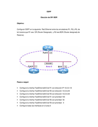
Objetivo:
Configurar OSPF en la siguiente Red Ethernet entre los enrutadores R1, R2 y R3, de
tal manera que R1 sea DR (Router Designado) y R2 sea BDR (Router designado de
Reserva).
Pasos a seguir
• Configure la interfaz FastEthernet0/0 de R1 con dirección IP 10.0.0.1/8
• Configure la interfaz FastEthernet0/0 de R2 con dirección 10.0.0.2/8
• Configure la interfaz FastEthernet0/0 de R3 con dirección 10.0.0.3/8
• Configure la interfaz FastEthernet0/0 de R1 con prioridad 100
• Configure la interfaz FastEthernet0/0 de R2 con prioridad 50
• Configure la interfaz FastEthernet0/0 de R3 con prioridad 0
• Configure todas las interfaces en el area 0
2. Preguntas a considerar
• ¿Cual es el tipo de red OSPF por defecto en segmentos Ethernet?
• ¿Este tipo de red tiene elección de DR/BDR?
• ¿Cuál es el rol del DR?
• ¿Cuál es el rol del BDR?
• ¿Cómo se da la elección del DR/BDR?
• ¿Cómo puede se influenciada la elección del DR/BDR?
• ¿Qué ocurre cuando un router de mas alta prioridad que el DR y BDR es agregado
al segmento?
Configuraciones
R1:
interface FastEthernet0/0
ip address 10.0.0.1 255.0.0.0
ip ospf priority 100
!
router ospf 1
network 10.0.0.1 0.0.0.0 area 0
R2:
interface FastEthernet0/0
ip address 10.0.0.2 255.0.0.0
ip ospf priority 50
!
router ospf 1
network 10.0.0.2 0.0.0.0 area 0
R3:
interface Ethernet0/0
ip address 10.0.0.3 255.0.0.0
ip ospf priority 0
!
router ospf 1
network 10.0.0.3 0.0.0.0 area 0
Verificación
R1#show ip ospf neighbor
Neighbor ID Pri State Dead Time Address
Interface
10.0.0.2 50 FULL/BDR 00:00:38 10.0.0.2 FastEthernet0/0
10.0.0.3 0 FULL/DROTHER 00:00:34 10.0.0.3 FastEthernet0/0
R2#show ip ospf neighbor
Neighbor ID Pri State Dead Time Address
Interface
10.0.0.3 0 FULL/DROTHER 00:00:33 10.0.0.3 FastEthernet0/0
10.0.0.1 100 FULL/DR 00:00:31 10.0.0.1 FastEthernet0/0
3. R3#show ip ospf neighbor
Neighbor ID Pri State Dead Time Address
Interface
10.0.0.2 50 FULL/BDR 00:00:34 10.0.0.2 Ethernet0/0
10.0.0.1 100 FULL/DR 00:00:39 10.0.0.1 Ethernet0/0
R1#show ip ospf interface ethernet0/0
Ethernet0/0 is up, line protocol is up
Internet Address 10.0.0.1/8, Area 0
Process ID 1, Router ID 10.0.0.1, Network Type BROADCAST, Cost: 10
Transmit Delay is 1 sec, State DR, Priority 100
Designated Router (ID) 10.0.0.1, Interface address 10.0.0.1
Backup Designated router (ID) 10.0.0.2, Interface address 10.0.0.2
Reflexión
El Router Designado (DR) y el Backup de Router Designado (BDR) son roles
asignados a los dispositivos en una red OSPF de tipo broadcast y no-broadcast a fin
de reducir las replicaciones de LSA en el segmento. Cuando un dispositivo quiere
enviar un LSA en la red, esta es enviada al DR. El DR es el responsable de enviar este
LSA de vuelta a todos los dispositivos en el segmento. El BDR se utiliza para
reemplazar al DR en el caso de un fallo en la red. Determinación de cual de los
dispositivos que serán el DR y BDR se basa en un proceso de erección.
Este proceso de elección es determinado por dos valores, la prioridad de interfaz y
router-id. La prioridad de interfaz es un número en el rango de 0 a 255, con valor por
defecto de 1 en todas las interfaces. Una prioridad OSPF de 0 indica que un
dispositivo no participará en la elección de DR / BDR, mientras que una prioridad de
255 indica que el dispositivo es el más probable para ser elegido DR. Si hay un
empate en la prioridad OSPF, el dispositivo con el más alto router-id será elegido.
EL router-id en OSPF puede ser seleccionado automáticamente o bien manualmente.
Para la selección automática del router elegirá la más alta dirección de loopback IP en
el router, sino hay direcciones de loopback, la dirección IP mas alta de cualquier
interfaz será la asignada. Cuando se deja la selección automática esta puede cambiar
si una nueva interfaz con una mayor dirección IP se asigna un router y el proceso
OSPF se reinicia. Como el router-id debe ser único para todo el dominio OSPF, se
recomienda que sea definido manualmente con el comando router-id en el marco del
proceso de OSPF.
Una ves dada la elección OSPF, los comandos ip ospf neighbor y show ip ospf pueden
ser utilizados para verificar cual fue electo DR y BDR.
4. OSPF sobre Frame Relay - Non-Broadcast
Objetivo:
Configurar OSPF sobre una red Frame Relay tipo non-broadcast entre R1, R4, y R5.
A fin de tener conectividad entre las VLAN A, VLAN B y VLAN C.
Pasos a seguir:
• Configure la interfaz Fast Ethernet de R1 con la direccion IP address 1.0.0.1/8
• Configure la interfaz Ethernet de R4 con la dirección IP 4.0.0.4/8
• Configure la interfaz Ethernet de R5 con la dirección IP 5.0.0.5/8
• Configure la interfaz serial principal de R1 con la dirección IP 10.0.0.1/8
• Configure la interfaz serial principal de R4 con la dirección 10.0.0.4/8
• Configure la interfaz serial principal de R5 con la dirección 10.0.0.5/8
5. • Configure la encapsulación Frame Relay en las interfaces seriales principales
de R1, R4 y R5.
• Deshabilite Frame-Relay Inverse-ARP en las interfaces seriales de R4 y R5.
• Configure un static mapping layer 3 a layer 2 en R1 para alcanzar 10.0.0.4 vía
DLCI 104 y 10.0.0.5 vía DLCI 105.
• Configure un static mapping layer 3 a layer 2 en R4 para alcanzar 10.0.0.1 y
10.0.0.5 vía DLCI 401.
• Configure un static mapping layer 3 a layer 2 en R5 para alcanzar 10.0.0.1 y
10.0.0.4 vía DLCI 501.
• Configure las interfaces seriales de R4 y R5 con prioridad OSPF 0
• Configure OSPF todas la interfaces de R1, R4 y R5 en el area 0
• Configure neighbor statements en R1 para R4 y R5 bajo el proceso OSPF
Preguntas a Considerar
• ¿Cual es el tipo de red por defecto en OSPF para una interfaz Frame Relay
multipunto?
• ¿Los LSAs para este tipo de redes son enviadas de forma unicast o multicast?
• ¿La elección DR/BDR es soportada por este tipo de redes?
Configuraciones
R1:
interface FastEthernet0/0
ip address 1.0.0.1 255.0.0.0
!
interface Serial0/0
ip address 10.0.0.1 255.0.0.0
encapsulation frame-relay
frame-relay map ip 10.0.0.4 104
frame-relay map ip 10.0.0.5 105
!
router ospf 1
network 0.0.0.0 255.255.255.255 area 0
neighbor 10.0.0.4
neighbor 10.0.0.5
R4:
interface Ethernet0/0
ip address 4.0.0.4 255.0.0.0
!
interface Serial0/0
ip address 10.0.0.4 255.0.0.0
encapsulation frame-relay
6. ip ospf priority 0
frame-relay map ip 10.0.0.1 401
frame-relay map ip 10.0.0.5 401
no frame-relay inverse-arp
!
router ospf 1
network 0.0.0.0 255.255.255.255 area 0
R5:
interface Ethernet0/0
ip address 5.0.0.5 255.0.0.0
!
interface Serial0/0
ip address 10.0.0.5 255.0.0.0
encapsulation frame-relay
ip ospf priority 0
frame-relay map ip 10.0.0.1 501
frame-relay map ip 10.0.0.4 501
no frame-relay inverse-arp
!
router ospf 1
network 0.0.0.0 255.255.255.255 area 0
Verificación
R1#show ip ospf neighbor
Neighbor ID Pri State Dead Time Address Interface
10.0.0.4 0 FULL/DROTHER 00:01:58 10.0.0.4 serial0/0
10.0.0.5 0 FULL/DROTHER 00:01:49 10.0.0.5 serial0/0
R4#show ip ospf neighbor
Neighbor ID Pri State Dead Time Address Interface
10.0.0.1 1 FULL/DR 00:01:47 10.0.0.1 serial0/0
R5#show ip ospf neighbor
Neighbor ID Pri State Dead Time Address Interface
10.0.0.1 1 FULL/DR 00:01:56 10.0.0.1 serial0/0
R1#show ip route
Codes: C - connected, S - static, I - IGRP, R - RIP, M - mobile, B - BGP
D - EIGRP, EX - EIGRP external, O - OSPF, IA - OSPF inter area
N1 - OSPF NSSA external type 1, N2 - OSPF NSSA external type 2
E1 - OSPF external type 1, E2 - OSPF external type 2, E - EGP
i - IS-IS, su - IS-IS summary, L1 - IS-IS level-1, L2 - IS-IS level-2
ia - IS-IS inter area, * - candidate default, U - per-user static route
o - ODR, P - periodic downloaded static route
Gateway of last resort is not set
C 1.0.0.0/8 is directly connected, FastEthernet0/0
O 4.0.0.0/8 [110/74] via 10.0.0.4, 00:01:49, Serial0/0
O 5.0.0.0/8 [110/74] via 10.0.0.5, 00:01:49, Serial0/0
C 10.0.0.0/8 is directly connected, Serial0/0
R4#show ip route
Codes: C - connected, S - static, I - IGRP, R - RIP, M - mobile, B - BGP
D - EIGRP, EX - EIGRP external, O - OSPF, IA - OSPF inter area
N1 - OSPF NSSA external type 1, N2 - OSPF NSSA external type 2
E1 - OSPF external type 1, E2 - OSPF external type 2, E - EGP
i - IS-IS, su - IS-IS summary, L1 - IS-IS level-1, L2 - IS-IS level-2
ia - IS-IS inter area, * - candidate default, U - per-user static route
o - ODR, P - periodic downloaded static route
7. Gateway of last resort is not set
O 1.0.0.0/8 [110/74] via 10.0.0.1, 00:02:26, Serial0/0
C 4.0.0.0/8 is directly connected, Ethernet0/0
O 5.0.0.0/8 [110/74] via 10.0.0.5, 00:02:26, Serial0/0
C 10.0.0.0/8 is directly connected, Serial0/0
R5#show ip route
Codes: C - connected, S - static, I - IGRP, R - RIP, M - mobile, B - BGP
D - EIGRP, EX - EIGRP external, O - OSPF, IA - OSPF inter area
N1 - OSPF NSSA external type 1, N2 - OSPF NSSA external type 2
E1 - OSPF external type 1, E2 - OSPF external type 2, E - EGP
i - IS-IS, su - IS-IS summary, L1 - IS-IS level-1, L2 - IS-IS level-2
ia - IS-IS inter area, * - candidate default, U - per-user static route
o - ODR, P - periodic downloaded static route
Gateway of last resort is not set
O 1.0.0.0/8 [110/74] via 10.0.0.1, 00:00:11, Serial0/0
O 4.0.0.0/8 [110/74] via 10.0.0.4, 00:00:11, Serial0/0
C 5.0.0.0/8 is directly connected, Ethernet0/0
C 10.0.0.0/8 is directly connected, Serial0/0
Reflexión
The default OSPF network type for a multipoint Frame Relay interface is non-
broadcast.
The OSPF network type non-broadcast transmits OSPF hellos packets as unicast, and
like the broadcast network type supports the DR/BDR election. As hello packets for this
network type are unicast, devices on the segment must be manually defined on the DR
and BDR with the neighbor statement under the OSPF process. Note that in the above
example the broadcast keyword is not added to the frame-relay map commands. This
is due to the fact that broadcast support is not needed since hello packets are sent as
unicast, not multicast.
As seen in the previous example, the DR in OSPF is responsible for distributing LSAs
to other devices on the segment. In order for this to occur, the DR must have direct
layer two connectivity to all devices on the segment. In hub-and-spoke NBMA
networks, this implies that the hub, and only the hub, should be candidate for the DR
election. This is due to the fact that the hub is the only device that has direct layer two
connectivity to all devices on the network.
As seen in the previous example, the OSPF DR election is based on the OSPF priority.
An OSPF priority of 0 dictates that the router will not participate in the election, while an
OSPF priority of 255 indicates that the router is most likely to be elected the DR.
However, recall that the OSPF DR election does not support preemption, and therefore
who wins the election can be dependent on the order that devices come on to the
segment. This implies that even if the hub has a priority of 255 configured it is possible
that another device on the segment could be elected the DR. Therefore, in order to
ensure that the hub is always elected the DR, the OSPF priority must be set to 0 on the
spoke routers.
To verify that adjacency has been established issue the show ip ospf neighbor
command. To verify what the OSPF network type is and who the DR/BDR is issue the
show ip ospf interface command.
8. Note that in the above show ip route output the next-hop values learned via OSPF to
not mimic the underlying partially meshed layer 2 topology. In other words, the routing
table on R4 says to use the next-hop value of 10.0.0.5 to reach 5.0.0.0, while in reality
R4 must send the traffic towards R1 first. This implies that R4 must have direct layer 3
to layer 2 resolution for the address 10.0.0.5 out the Frame Relay interface, while R5
must likewise have direct layer 3 to layer 2 resolution for the address 10.0.0.4 out the
FrameRelay interface.
OSPF sobre Frame Relay – Broadcast
Objetivo:
Configurar OSPF sobre una red Frame Relay tipo broadcast entre R1, R4, y R5. A
fin de tener conectividad entre las VLAN A, VLAN B y VLAN C
R4
9. Pasos a Seguir:
• Configure la interfaz Fast Ethernet de R1 con la dirección IP address 1.0.0.1/8
• Configure la interfaz Ethernet de R4 con la dirección IP 4.0.0.4/8
• Configure la interfaz Ethernet de R5 con la dirección IP 5.0.0.5/8
• Configure la interfaz serial principal de R1 con la dirección IP 10.0.0.1/8
• Configure la interfaz serial principal de R4 con la dirección 10.0.0.4/8
• Configure la interfaz serial principal de R5 con la dirección 10.0.0.5/8
• Configure la encapsulación Frame Relay en las interfaces seriales principales
de R1, R4 y R5.
• Deshabilite Frame-Relay Inverse-ARP en las interfaces seriales de R4 y R5.
• Configure un static mapping layer 3 a layer 2 en R1 para alcanzar 10.0.0.4 vía
DLCI 104 y 10.0.0.5 vía DLCI 105.
• Configure un static mapping layer 3 a layer 2 en R4 para alcanzar 10.0.0.1 y
10.0.0.5 vía DLCI 401.
• Configure un static mapping layer 3 a layer 2 en R5 para alcanzar 10.0.0.1 y
10.0.0.4 vía DLCI 501.
• Asegure que los paquetes broadcast y multicast puedan ser enviados en todo
el circuito
• Configure OSPF network type broadcast en las interfaces seriales de R1, R4 y
R5.
• Configure las interfaces seriales de R4 y R5 con prioridad OSPF 0
• Configure OSPF todas la interfaces de R1, R4 y R5 en el area 0
Preguntas a Considerar
• ¿Cual es el tipo de red por defecto en OSPF para una interfaz Frame Relay
multipunto?
• ¿Los LSAs para este tipo de redes son enviadas de forma unicast o multicast?
• ¿La elección DR/BDR es soportada por este tipo de redes?
Configuraciones
R1:
interface FastEthernet0/0
ip address 1.0.0.1 255.0.0.0
!
interface Serial0/0
ip address 10.0.0.1 255.0.0.0
10. encapsulation frame-relay
ip ospf network broadcast
frame-relay map ip 10.0.0.4 104 broadcast
frame-relay map ip 10.0.0.5 105 broadcast
!
router ospf 1
network 0.0.0.0 255.255.255.255 area 0
R4:
interface Ethernet0/0
ip address 4.0.0.4 255.0.0.0
!
interface Serial0/0
ip address 10.0.0.4 255.0.0.0
encapsulation frame-relay
ip ospf network broadcast
ip ospf priority 0
frame-relay map ip 10.0.0.1 401 broadcast
frame-relay map ip 10.0.0.5 401
no frame-relay inverse-arp
!
router ospf 1
network 0.0.0.0 255.255.255.255 area 0
R5:
interface Ethernet0/0
ip address 5.0.0.5 255.0.0.0
!
interface Serial0/0
ip address 10.0.0.5 255.0.0.0
encapsulation frame-relay
ip ospf network broadcast
ip ospf priority 0
frame-relay map ip 10.0.0.1 501 broadcast
frame-relay map ip 10.0.0.4 501
no frame-relay inverse-arp
!
router ospf 1
network 0.0.0.0 255.255.255.255 area 0
Verificaciones
R1#show ip ospf neighbor
Neighbor ID Pri State Dead Time Address Interface
10.0.0.4 0 FULL/DROTHER 00:00:33 10.0.0.4 Serial0/0
10.0.0.5 0 FULL/DROTHER 00:00:36 10.0.0.5 Serial0/0
R4#show ip ospf neighbor
Neighbor ID Pri State Dead Time Address Interface
10.0.0.1 1 FULL/DR 00:00:39 10.0.0.1 Serial0/0
R5#show ip ospf neighbor
Neighbor ID Pri State Dead Time Address Interface
10.0.0.1 1 FULL/DR 00:00:33 10.0.0.1 Serial0/0
11. R1#show ip route
Codes: C - connected, S - static, I - IGRP, R - RIP, M - mobile, B –
BGP D - EIGRP, EX - EIGRP external, O - OSPF, IA - OSPF inter area
N1 - OSPF NSSA external type 1, N2 - OSPF NSSA external type 2
E1 - OSPF external type 1, E2 - OSPF external type 2, E - EGP
i - IS-IS, su - IS-IS summary, L1 - IS-IS level-1, L2 - IS-IS level-2
ia - IS-IS inter area, * - candidate default, U - per-user static
route o - ODR, P - periodic downloaded static route
Gateway of last resort is not set
C 1.0.0.0/8 is directly connected, FastEthernet0/0
O 4.0.0.0/8 [110/74] via 10.0.0.4, 00:01:49, Serial0/0
O 5.0.0.0/8 [110/74] via 10.0.0.5, 00:01:49, Serial0/0
C 10.0.0.0/8 is directly connected, Serial0/0
R4#show ip route
Codes: C - connected, S - static, I - IGRP, R - RIP, M - mobile, B –
BGP D - EIGRP, EX - EIGRP external, O - OSPF, IA - OSPF inter area
N1 - OSPF NSSA external type 1, N2 - OSPF NSSA external type 2
E1 - OSPF external type 1, E2 - OSPF external type 2, E – EGP i - IS-
IS, su - IS-IS summary, L1 - IS-IS level-1, L2 - IS-IS level-2 ia -
IS-IS inter area, * - candidate default, U - per-user static route
o - ODR, P - periodic downloaded static route
Gateway of last resort is not set
O 1.0.0.0/8 [110/74] via 10.0.0.1, 00:02:26, Serial0/0
C 4.0.0.0/8 is directly connected, Ethernet0/0
O 5.0.0.0/8 [110/74] via 10.0.0.5, 00:02:26, Serial0/0
C 10.0.0.0/8 is directly connected, Serial0/0
R5#show ip route
Codes: C - connected, S - static, I - IGRP, R - RIP, M - mobile, B –
BGP D - EIGRP, EX - EIGRP external, O - OSPF, IA - OSPF inter area
N1 - OSPF NSSA external type 1, N2 - OSPF NSSA external type 2
E1 - OSPF external type 1, E2 - OSPF external type 2, E – EGP i - IS-
IS, su - IS-IS summary, L1 - IS-IS level-1, L2 - IS-IS level-2 ia -
IS-IS inter area, * - candidate default, U - per-user static route
o - ODR, P - periodic downloaded static route
Gateway of last resort is not set
O 1.0.0.0/8 [110/74] via 10.0.0.1, 00:00:11, Serial0/0
O 4.0.0.0/8 [110/74] via 10.0.0.4, 00:00:11, Serial0/0
C 5.0.0.0/8 is directly connected, Ethernet0/0
C 10.0.0.0/8 is directly connected, Serial0/0
Reflexiones
The OSPF network type broadcast transmits OSPF hellos packets as multicast, and
like the non-broadcast network type supports the DR/BDR election. This network type
is default on broadcast medias such as Ethernet and Token-Ring. Note that in the
above example the broadcast keyword is added to the frame-relay map commands, as
opposed to the previous example. This is due to the fact that broadcast support is
needed since hello packets are sent as multicast, not unicast. Furthermore, since
12. unicast updates do not need to be configured, the neighbor statement is not required
on the DR and BDR.
As seen in the previous examples, the DR in OSPF is responsible for distributing LSAs
to other devices on the segment. In order for this to occur, the DR must have direct
layer two connectivity to all devices on the segment. In hub-and-spoke NBMA
networks, this implies that the hub, and only the hub, should be candidate for the DR
election. This is due to the fact that the hub is the only device that has direct layer two
connectivity to all devices on the network. As seen in the previous examples, the OSPF
DR election is based on the OSPF priority. An OSPF priority of 0 dictates that the
router will not participate in the election, while an OSPF priority of 255 indicates that
the router is most likely to be elected the DR.
However, recall that the OSPF DR election does not support preemption, and therefore
who wins the election can be dependent on the order that devices come on to the
segment. This implies that even if the hub has a priority of 255 configured it is possible
that another device on the segment could be elected the DR. Therefore, in order to
ensure that the hub is always elected the DR, the OSPF priority must be set to 0 on the
spoke routers.
To verify that adjacency has been established issue the show ip ospf neighbor
command. To verify what the OSPF network type is and who the DR/BDR is issue the
show ip ospf interface command. Note that in the above show ip route output the next-
hop values learned via OSPF to not mimic the underlying partially meshed layer 2
topology. In other words, the routing table on R4 says to use the next-hop value of
10.0.0.5 to reach 5.0.0.0, while in reality R4 must send the traffic towards R1 first. This
implies that R4 must have direct layer 3 to layer 2 resolution for the address 10.0.0.5
out the Frame Relay interface, while R5 must likewise have direct layer 3 to layer 2
resolution for the address 10.0.0.4 out the Frame Relay interface.