2. TABLE OF CONTENTS
PAGE
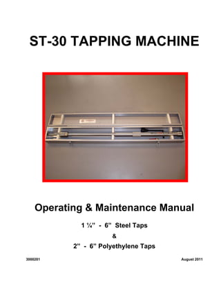
I. ST-30 TAPPING MACHINE
A. Introduction 1
B. Purpose of Tapping Machine 1 - 2
C. Safety 2 - 3
D. ST30 Tapping Machine & Equipment 3 - 5
E. Tapping Valve Requirements 5
F. Tapping Machine Operation 5 - 7
II. TAPPING OPERATIONS
A. General Information 7
B. Tapping with a Drill 7 - 13
C. Tapping with a Hole Saw 13 - 18
III. COMPLETION PLUG OPERATIONS
A. General Information 18
B. Install 2” MTD Purge & Equalization Fitting 19 - 22
C. Remove 2” MTD Purge & Equalization Fitting 22 – 24
D. Install 1 ¼” – 3” MTDTAPSTOP Square Drive
Completion Plug 24 – 28
E. Remove 1 ¼” – 3” MTDTAPSTOP Square Drive
Completion Plug 28 - 30
IV. MAINTENANCE
A. General maintenance 30
B. Machine Assembly/Disassembly 30 - 32
V. PARTS LIST 33 - 34
3. 1
I. ST-30 TAPPING MACHINE
A. Introduction
In this manual we provide the operator with recommended operation and maintenance
instructions for safe and effective operation of the MTD ST-30 Tapping Machine. We also
familiarize the operator with the capabilities of the equipment. The ST-30 equipment is
designed with adequate safety factors as long as manufacturer’s recommended
specifications are not exceeded.
It is important to read the entire manual before operating the ST-30 Tapping Machine and
carefully adhere to the manual for all safety, operation and maintenance procedures.
Before performing field operations, make a test tap on a short length of pipe.
Should you have any questions concerning the ST-30 Tapping machine or its use, contact
M. T. Deason Company, Inc.
Picture 1: ST-30 TAPPING MACHINE
WARNING: Do not attempt any tapping operation departing from the procedures
prescribed in this manual. Attempting such an unauthorized procedure
could present a hazardous situation resulting in personal injury and/or
property damage. Do not alter this machine or any of its component parts.
Use only MTD adapters, accessories, and replacement parts manufactured
or recommended by MTD. Any alteration of this machine or use of
adapters, accessories, or parts not manufactured or recommended by MTD
could cause the machine to malfunction, resulting in damage to the
machine and/or personal injury.
B. Purpose of Tapping Machine
► ST-30 Tapping Machine can be used for industrial, natural gas and water applications
► Hot Tapping metal or polyethylene pipe for plugging operations
► Install completion plug in metal and polyethylene control fittings
1. Specifications
The specifications of the ST30 Tapping Machine are shown in Chart 1
2. Equipment
Chart 2 provides a list of equipment used in performing various options with the ST-
30 Tapping Machines.
4. 2
Chart 1: MTD ST-30 TAPPING MACHINE SPECIFICATIONS
Description/Function Size/Rating
Maximum Operating Pressure 1480 psi at 100° F
Maximum Operating Temperature 700° F at 700 psi
700° F (371°C) for intermittent service only. Maximum continuous
rating 350° F (177° C) at 1,025 psi (70bar).
Sizes:
Using twist drills
Using hole saws
½”, ¾”, 1”, 1 ¼”, 1 7/16”
1 ¼”, 1 ½”, 2”, 3”,4”, 6”
Maximum boring bar travel 30”
Machine weight 45 lbs.
Rate of travel Manual feed, 1/8” per revolution
Operation: machine is manually operated or may be operated with an optional air motor and socket adapter.
Chart 2: ST-30 TAPPING MACHINE EQUIPMENT
TERMS DESCRIPTION & FUNCTION SIZES
ST-30 Tapping Machine
Part # ST30-1480-0000
Manual or power driven machine which taps into
pipe.
Valve Adapter
(threaded & flanged)
Extension that attaches tapping machine thread
end to tapping valve and houses drills, cutters,
and completion plugs.
Threaded: 1”, 1 ¼”, 1 ½”,
2”, 3”
Flanged: 2”, 3”, 4”, 6”;
Class 150, 300 or 600
Drill High-speed steel bore bit that cuts entry into pipe. See ST-30 Tapping
Machine Parts List
Section V
Hole Saw and Holder Pilot One-piece steel cup with cutting edge that cuts
through pipe. Holder pilot retains the coupon.
See ST-30 Tapping
Machine Parts List
Section V
2” 600# Purge & Equalization
Plug Holder
A steel device that holds and guides a completion
plug into fitting
2” 600# Purge & Equalization
Fitting
A steel nipple and completion plug used to gain
entry into pipelines.
2”
Air Motor (optional)
Part # ST30-6000-0000
Hose-connected, hand-held power tool which can
be used rather than manually operating Tapping
machine ratchet handle.
Right angle
Socket Adapter (optional)
Part # ST30-6005-0000
Drive socket adapter connecting air motor to hex
drive on tapping machine.
¾” size
C. Safety
Learn location and function of all safety features built into the MTD ST-30 Tapping
Machines and related equipment. Wear protective, fire retardant clothing and safety
glasses.
1. Bleeder Valve Connection
The bleeder valve connection is located on the Tapping Machine near bottom of
body tube. See Picture 2. The bleeder valve serves to test, purge air from fitting
and bleed off pressure after tap is complete. (After the drill or hole saw is retracted
and tapping valve is closed.)
5. 3
Picture 2: Bleeder Valve Connection
2. Warning and Caution
The purpose of Warnings and Cautions in this manual is to call the operator’s
attention to possible danger of injury to personnel and/or property damage to
equipment and deserves careful attention and understanding.
a. WARNING: Indicates a potentially hazardous situation which, if not avoided,
could result in death or serious injury and damage to equipment and fittings.
b. CAUTION: Indicates a potentially hazardous situation which, if not avoided,
may result in personal injury and damage to equipment and fittings. It may also
be used to alert against unsafe practices.
3. Protective Clothing
Protective clothing is recommended whenever working around machinery.
Suggestions are: hard hat, safety glasses. gauntlet gloves, safety shoes, fire
retardant garments to cover exposed areas of skins, and breathing apparatus when
toxic atmosphere exists.
D. Tapping Machine, Equipment, Terms & Vocabulary
1. ST-30 Tapping Machine
1. Feed Tube
2. Body Tube
3. Boring Bar
4. Ratchet
Handle
5. Bleeder Valve
Connection
Picture 3: ST-30 Tapping Machine
4
1
2
5
3
6. 4
2. Adapters
Picture 4: Adapters
CAUTION: Use only MTD valve adapters to assure correct alignment
of equipment. Commercial pipe fittings are not machined
for concentric alignment. Misalignment can result in
equipment and fitting damage.
3. Hole Saws and Drills
Picture 5. Hole Saws and Holder Pilot
4. Completion Plugs and Holders
Picture 6: Completion Plugs and Holders
5. Accessories
Picture 7: Right Angle Air Motor
7. 5
E. Tapping Valve Requirements
Chart 3: Valves to Use with Drills (see Note 1)
Drill Diameter Drill Length Minimum Valve Size Minimum Thru-Bore Notes
½” 6” 1 ¼” 1.250” (2)
½” 22 ¼” 1” 1.000” (3)
¾” 6” 1 ¼” 1.250” (2)
¾” 22 ¼” 1” 1.000” (3)
1” 6” 1 ¼” 1.250” (2)
1 ¼” 6” 1 ½” 1.5000” (4)
1 7/16” 7 3/8” 1 ½” 1.5000” (4)
NOTES:
(1) The valve minimum size and minimum thru-bore listed above are the minimum sizes that will
accommodate the drill. If a completion plug or other drives is to be set in the line at the
completion of operations, the valve will have to be of sufficient thru-bore to accommodate the
device. See Chart 4.
(2) A 1.250” minimum bore to allow passage of boring bar.
(3) If a 1” threaded valve is used, the longer adapter and drill are required because of boring bar
diameter.
(4) 1.500” minimum bore required to allow passage of drill diameters.
Chart 4: Valves to Use with Hole Saws and Completion Plugs (Size-on-Size)
Nominal Size Valve Size Thru-Bore Min. ID
1 ¼” 2” threaded 1-5/16”
1 ½” 2” threaded 1-11/16”
2” 2” threaded 2-1/16”
3” 3” threaded 3-1/16”
4” 4” flanged 4-1/32”
6” 6” flanged 6-1/8”
Chart 5: Valves for Purge & Equalization Fittings
Hole Saw Valve Size Thru-Bore Min. ID
1 ½” 2” 2-1/16”
1 ½” 2” 2–1/16”
F. Tapping Machine Operation
1. Remove the locking cap. See Picture 8. The locking cap locks the feed tube and
boring bar together, permitting extension and rotation of the boring bar at the same
time. This feature is used only when setting some completion plugs and when
retracting the boring bar with the ratchet handle under high pressure. In this latter
case, make sure the locking cap remains in place.
8. 6
Picture 8: Locking Cap Picture 9: Feed Tube
2. Hold body tube and rotate feed tube clockwise by hand. Notice that boring bar
extends, but does not rotate. See Picture 9.
3. Hold feed tube and rotate hex
drive clockwise with ratchet
handle. Notice that the boring
bar rotates but does not extend
or retract. See Picture 10.
Picture 10: Turn Ratchet Handle
4. Hold hex drive and rotate feed tube counterclockwise. The boring bar retracts, but
does not rotate.
5. Re-install locking cap (Picture 8). With ratchet handle, rotate hex drive clockwise.
Note that boring bar and feed tube rotate and boring bar extends.
6. With ratchet handle, rotate hex drive counterclockwise. Note that boring bar rotates
and retracts
7. Feed (Manual)
The ST-30 Tapping Machine is a manual feed machine. Clockwise rotation of the
feed tube extends the boring bar and counterclockwise rotation retracts the boring
bar. With the locking cap installed, turning the hex drive clockwise both turns and
extends the boring bar. One revolution of the hex drive will extend the boring bar
1/8th
inch.
Note: The locking cap is to be used only when setting and removing P&E Fitting
Completion Plugs. Do not tap or drill with the locking cap installed.
CAUTION: When tapping, be sure you do not overfeed. Overfeeding and underfeeding
will damage the drill or hole saw.
9. 7
8. Air Motor
a. The air-motor drive for the Tapping Machine is available from MTD, and
requires a ¾, 6-point, heavy-duty socket to fit the ¾ hex drive.
b. Since the air motor has a maximum speed greater than required, an air
regulator is provided to regulate the air volume to meet the various size hole
saw maximum speed recommendations. RPM of the air motor is controlled by
adjusting the slotted screw in the air regulator, as shown in Picture 11, by
turning it either clockwise or counterclockwise. Because of the necessity to
closely regulate the cutter or drill speed, it is recommended that only the air
motor and associated regulator provided by MTD be used with the ST-30
machine. Because of the danger of sparks, an electric drive motor should
never be used.
Picture 11: Air Motor with Air
Regulator
Picture 12: Using Air Motor
Chart 6: Recommended Tapping Speeds
Nominal Hole Size (in.) Hole Saw Max. rpm Drill Max rpm
1-1/4, 1-1/2, 2 195
3 120
4 100
6 80
195
(all sizes)
Note: Hole saw speeds in Chart 6 are recommended for mild steel under ideal conditions. The
air motor should be held with both hands, with arms extended, as shown in Picture 12.
WARNING: When an air motor is used, two operators are required to run the machine - one to
operate the air motor, and one to operate the feed manually by turning feed tube. Do not exceed
maximum RPM for any given size. Excessive hole saw wear may result. Do not overfeed drill or
hole saw causing binding during cutting and possible loss of control of air motor resulting in
possible personal injury and/or equipment damage.
II. TAPPING OPERATIONS
A. General Information
It is strongly recommended that the operator become familiar with all Tapping Machine
operation procedures. Practice operating the machine to become accustomed to the
controls before performing an actual hot tap in the field. A test setup should be made on a
short length of pipe to practice with the tapping procedure.
B. Tapping with a Drill
1. Select Equipment
Select the correct tapping valve by consulting Chart 3, Section I, for minimum
dimensions.
10. 8
Note: Select a tapping valve that will allow drill, boring bar, and completion plug to
pass through valve bore without damaging the drill or valve. The bore
should be unobstructed by seat ring lugs. Bore minimum inside diameter
must correspond to through-bore minimum inside diameter in Chart 3,
Section I.
2. Assemble Equipment
a. After nipple has been welded to the pipe, wrap sealing tape or apply sealing
compound to nipple threads. Next, thread tapping valve to nipple. See Picture
13. Open valve fully. When a flanged valve is used, the center of the valve
through-bore must be concentric with the flanged fitting through-bore.
Picture 13: Install Tapping Valve
CAUTION: Do not over tighten valve. Over tightening can swage the nipple or
fitting diameter too small to set the completion plug.
b. Hold the ST-30 body tube and rotate feed tube clockwise to extend boring bar
until retainer spring can be removed. Remove retainer spring. See Picture 14.
Insert drill into boring bar and reinstall retainer spring. See Picture 15
Picture 14:
Remove Retainer Spring
Picture 15:
Insert Drill & Replace Retainer Spring
Install valve adapter. Use thread compound on threads of valve adapter to
assure a tight seal. Thread adapter to Tapping Machine. See Picture 16.
11. 9
Picture 16: Install Valve Adapter
CAUTION: Use only MTD valve adapters to assure correct alignment of
equipment. Commercial pipe fittings are not machined for concentric
alignment. Misalignment can result in equipment damage.
c. Hold body tube of Tapping
Machine and rotate feed tube
counterclockwise until feed
tube is at “zero” mark on
body tube. See Picture 17.
Drill is completely retracted.
Picture 17: Zero indicated
on Body Tube
3. Compute Travel Distance
a. Travel distance is that distance the drill must travel from the zero mark on the
body tube to the point that the drill has fully penetrated the pipe. It has two
components: lower-in distance and drilling distance.
WARNING: Improper measurements may result in tapping through bottom of pipe.
12. 10
b. Calculate lower-in distance required for drill tip to contact pipe. (Boring bar fully
retracted and feed tube at zero mark on body tube.) See Figure 18.
c. Measure and record distance “A”, tip of drill to valve adapter face. If threaded
adapter is used, “A” must be adjusted for thread makeup between adapter and
tapping valve. Thread makeup varies and must be measured each time. If:
(1) Tip of drill is inside adapter, thread makeup is subtracted from “A” and the
result added to “B” in determining lower-in distance. See Figure 18a.
(2) Tip of drill extends below valve adapter face, thread makeup is added to
“A” and the result subtracted from “B” in determining lower-in distance.
See Figure 18b.
d. Measure and record distance “B”, valve face to top of pipe to be tapped. Valve
must be tight on fitting.
e. The sum of these measurements should be the body tube reading when drill
contacts the pipe. Mark this measurement on the body tube. See Picture 19.
Picture 19: Mark Body Tube
13. 11
f. Measure and record distance “J”, top of valve face to top of fitting. Retain this figure for
use when setting completion plug.
g. Examples Assume we are using a MTD threaded adapter.
Example 1: Figure 18a
Tip of drill is inside valve adapter face.
■ If distance “A” measure 3” with thread makeup subtracted;
■ And distance “B”: measure 8-1/2”
■ Then calculate:
Distance “A” 3”
Add distance “B” 8 ½”
TOTAL 11 ½”
Feed tube should be at 11 ½” on body tube as drill tip contacts pipe.
Example 2: Figure 18b
Tip of drill extends below valve adapter face.
■ If distance “A” measures 1 ½” with thread makeup added
■ And distance “B” measures 8 ½”
■ Then calculate:
Distance “A” minus -1 ½”
Distance “B” is 8 ½”
TOTAL 7”
Feed tube should be at 7” on body tube as drill tip contacts pipe.
h. Calculate drilling distance for drill to fully penetrate pipe. Multiply 4/5 (0.8)* times the drill
diameter and add the pipe wall thickness.
Example: Assume you are drilling ¾” (.75) hole through a 5/32” (.156) wall
thickness pipe. .8 x .75 = .600 + .156 = .756 or about 3/4”.
* 0.8 times drill diameter allows full drill diameter into the pipe.
i. Travel distance (distance required to complete the tap) equals lower-in distance plus
drilling distance. Add these figures and mark on body tube.
CAUTION: If the total of these figures exceeds 30”, maximum boring bar travel for the ST-30,
the tap cannot be completed with the ST-30 Tapping Machine.
4. Install Equipment
a. Apply thread compound on adapter threads to insure a tight seal. See picture 20.
Picture 20: Apply Thread Compound Picture 21: Install Tapping Machine
b. Attach machine to tapping valve. See Picture 21. Close and open valve to make sure that
14. 12
it works properly and that the drill does not interfere with opening and closing of valve disc.
Be sure valve is in full open position before continuing to next step.
c. Remove pipe plug from Tapping Machine bleeder valve connection. Make sure bushing is
not removed along with the pipe plug.
Picture 22: Install and Open Bleeder Valve
d. Thread bleeder valve and ¼” nipple into bushing. See Picture 22.
e. Test setup for pressure tightness by pressuring through bleeder valve on Tapping
Machine. Leave bleeder valve open after test.
CAUTION: When conducting pressure test, do not exceed internal pipeline pressure.
5. Make a Tap
a. By rotating feed tube clockwise, extend drill until it contacts pipe. See Picture 23. The
feed tube should be at the first mark on the body tube (lower-in distance). Rotate slowly
during the last inch of travel to prevent damage to the drill tip. After the measurement has
been checked, turn tube counterclockwise ¾ of a turn before proceeding to the next step.
Picture 23: Rotate Feed Tube Picture 24: Attach and Turn Ratchet
b. Attach ratchet handle to ¾” hex drive. While a ratchet handle is furnished, best results will
be obtained if handle is rotated a full 360° while cutting. Turn clockwise only. See Picture
24. If air motor is used, review Section I-F8 “Air Motor” for important instructions. The
rate of advance for the drill is determined by the advance of the feed tube. Eight
15. 13
revolutions of the feed tube will lower the drill one inch.
c. As the drill is turned by rotating the ratchet handle, turn the feed tube clockwise to
continue lowering the drill.
d. As the drill penetrates the pipe wall, allow line fluid to completely fill valve and fitting to
purge all air. See Picture 25. Close bleeder valve after air is purged.
Picture 25: Purge Air through bleeder Valve
WARNING: Vent pressure bleed valve away from work area and personnel. Stand
clear of bleeder valve. Personal injury may result from blowing debris.
Note: If machine stalls during tap, turn feed tube counterclockwise until drill is
free. Resume tapping (with slower feed) to clean burr from hole by turning
ratchet handle and reducing the rate of turning the feed tube.
e. When second mark (total travel distance) is reached on body tube, tap should be
complete. At this point, the feed tube should turn with little effort. The “feel” and rate of
feed confirm the tap to be complete. Rotate feed tube one complete revolution clockwise.
Feed tube should turn freely.
WARNING: Do not tap through the bottom of the pipe.
f. Retract drill until feed tube is at zero mark on the body tube by rotating feed tube
counterclockwise. If line is under high pressure, it may be necessary to install the locking
cap and retract the boring bar by using the ratchet handle. Refer to Section I-F1.
C. Tapping with a Hole Saw
The use of hole saws is recommended only for size-on-size taps, i.e. 2” tap on 2” line, etc. If used
on other than size-on-size, a flat-plate cutting condition will be encountered as pipe diameter and
wall thickness increase, making completion of the tap and retention of coupon difficult. Therefore,
a drill is recommended for other than size-on-size.
Consult Parts List, Section V, for part numbers of hole saws and holder pilots
1. Select Equipment
a. Select proper tapping valve using dimensions in Chart 4, attach to tapping fitting, and open
to full-open position.
Note: The tapping valve must allow the hole saw to pass through the bore unobstructed
without damage to the hole saw or valve. The bore should be unobstructed by seat
ring lugs, etc. The bore of the valve must be round and the minimum inside diameter
must correspond to through-bore minimum inside diameter dimension in Chart 4,
Section I.
b. Select proper holder pilot, hole saw, and valve adapter from Parts List, Section V. Be sure
that U-wire in holder pilot works freely and moves from side to side by its own weight. See
Picture 26.
16. 14
Picture 26: Check U-Wire Picture 27: Attach Adapter to Tapping
Machine
2. Equipment Assembly
a. Install adapter. Use thread compound on threads of the valve adapter. See Picture 27.
CAUTION: Use only MTD valve adapters to assure correct alignment of equipment.
Misalignment can result in equipment damage.
b. Attach hole saw to holder pilot. See Pictures 28 and 29.
Picture 28: Attach Hole Saw to Holder
Pilot
Picture 29: Attach Hole Saw to Holder
Pilot
Picture 30: Remove Retainer Spring Picture 31: Insert Hole Saw in Tapping
Machine
c. While holding body tube, rotate feed tube clockwise to extend boring bar until retainer
spring can be removed. Remove retainer spring. See Picture 30.
d. Insert holder pilot into boring bar and attach retainer spring. See Picture 31.
DO NOT USE GREASE IN HOLE SAWS. GREASE IN HOLE SAW CAN COLLECT
CHIPS AND DEPOSIT THEM IN INTERNAL THREADS DURING RETRACTION.
17. 15
e. While holding body tube, rotate feed tube counterclockwise until feed tube is at zero mark
on body tube.
3. Compute Travel Distance
a. Travel distance is that distance the hole saw must travel to complete the tap and is
measured from the zero mark on the body tube to the point at which the saw has cut
completely through the pipe and has retained the coupon. It has two components:
lower-in distance and cutting distance.
b. Calculate lower-in distance for pilot drill tip to contact pipe. (Boring bar fully retracted
and feed tube at zero mark on body tube.) Refer to Figures 32 or 33.
c. Measure and record distance “A”, tip of holder pilot drill to valve-adapter face. If
threaded adapter is used, subtract thread makeup between adapter and tapping valve.
Thread makeup is not constant. It must be measured each time.
d. Measure and record distance “B”, valve face to top of pipe to be tapped.
e. The sum of these two measurements should be the body tube reading when the pilot
drill contacts the pipe. Mark this measurement on the body tube.
f. Measure and record distance “J”, top of valve face to top of fitting. Retain this figure for
later use when setting completion plug.
g. Example:
Assume we are using a threaded valve adapter.
1. If distance “A” measure 2 inches after thread makeup is subtracted, and
2. Distance “B” is 12 inches, then
3. The total lower-in distance would be 14 inches.
h. Determine cutting distance.
i. For size-on-size taps (2” tap on 2” pipe, or 4” on 4” pipe), cutting distance for standard
weight pipe is shown in Chart 7.
18. 16
Chart 7: Cutting Distance for Standard Wall Pipe
(Pilot Touch to Clean-up)*
Tap Size
(in.)
Pipe Size
(in.)
1.25 1.5 2 2.5 3 4 6
1.25 1.114 1.088 1.798 1.752 1.710 1.673 1.635
1.5 1.247 1.920 1.841 1.777 1.721 1.665
2 1.549 1.681 1.570 1.482 1.399
3 1.949 1.854 1.612
4 2.750 2.328
6 2.422
* Clean-up is OD of the cutter through ID of pipe plus 1/8”
Note: If a size-on-size tap is being made on heavy wall pipe, make sure that the ID of the pipe is larger
than the OD of the cutter in order to complete a successful tap and retain the coupon. See Picture 31.
j. Travel distance (distance required to complete the tap) equals lower-in distance, total of
measurements “A” and “B” plus cutting distance, from Chart 7. Add these figures and
mark on body tube.
4. Install Equipment
CAUTION: When using flanged adapter, make sure bore of tapping valve and bore of
fitting are in alignment.
a. Apply thread compound to adapter threads and attach machine to tapping valve. See
Picture 35. Operate valve to make sure it opens and closes without interference from tip
of pilot drill. Be sure valve is in full-open position before continuing to next step.
b. Remove pipe plug from bleeder valve connection and install bleeder valve and nipple.
Open bleeder valve. See Picture 36.
Picture 35: Install Tapping Machine Picture 36: Install and Open Bleeder Valve
WARNING: Make sure bleeder valve is in open position. If not, open it.
c. Test setup for pressure tightness by pressuring through bleeder valve on Tapping
Machine.
CAUTION: When conducting pressure test, do not exceed internal pipeline pressure.
5. Make a Tap
a. By rotating feed tube clockwise, extend pilot drill until it contacts pipe. The feed tube
should be at the first mark on the body tube (lower-in distance). Rotate slowly during
last inch of travel to prevent damage to the tip of the pilot drill. After measurement has
been checked, turn feed tube counterclockwise three-quarters of a turn before
proceeding to the next step.
19. 17
b. Attach ratchet handle to ¾” hex drive. See Picture 37. While a ratchet handle is
furnished, best results will be obtained if handle is rotated 360° while cutting. Turn
clockwise only. If air motor is used, review Section I-F8, “Air Motor Operation,” for
important instructions. The rate of advance for the hole saw is determined by the
advance of the feed tube. Do not overfeed to prevent damage to the pilot drill or hole
saw. Eight revolutions of the feed tube will lower the hole saw one inch.
Picture 37: Attach and Turn
Ratchet
Picture 38: Purge Air through Bleeder Valve
c. As the pilot drill penetrates the pipe wall, allow line fluid to completely fill valve and fitting
to purge all air. See Picture 38. Close bleeder valve.
WARNING: Stand clear of bleeder valve. Personal injury might result from blowing
debris.
Note: As the tap nears completion, the cutting noise may become louder and more
irregular. This is caused by the coupon changing shape or relieving stress. If
the pipe is highly stressed at the tapping location, the hole saw may become
locked by the loosened coupon spreading out. In this case retract hole saw
by turning feed tube one revolution counterclockwise. Resume tap (with a
slower feed) to clear burr from hole.
d. When the second mark (total travel distance) is reached on body tube, tap should be
complete. At this point, the feed tube should turn with little effort. The “feel” and rate of
feed confirm the tap to be complete.
CAUTION: When tapping size on size, do not travel more than 1-7/16” after pilot drill
touches pipe for 1-1/4” taps; 1-5/8” for 1-1/2” taps; 1-7/8” for 2” taps; or 2-
1/2” for 3” and 4” taps. If these distances are exceeded, the hole saw or
pilot drill will damage or penetrate the lower half of the pipe.
6. Recover Equipment
a. By rotating feed tube counterclockwise, retract hole saw until feed tube is at the zero
mark on the body tube or until it comes to a firm stop. If line is under high pressure, it
may be necessary to install the locking cap and retract the hole saw by using the ratchet
handle. Refer to Section I-F1.
b. By rotating feed tube counterclockwise, retract hole saw until feed tube is at the zero
mark on the body tube or until it comes to a firm stop. If line is under high pressure, it
may be necessary to install the locking cap and retract the hole saw by using the ratchet
handle. Refer to Section I-F1.
20. 18
c. Bleed off pressure trapped in valve adapter by opening bleeder valve on Tapping
Machine. Stand clear of bleeder valve.
d. Remove bleeder valve.
e. Remove machine from tapping valve.
CAUTION: High-temperature taps: after each high-temperature tap above 350° F, or
taps in corrosive fluids, replacement of packing is recommended. (For procedure to
replace packing see Section IV.) Equipment damage might otherwise result.
f. Remove coupon (Picture 39). To enable coupon to slide off pilot drill, coupon must be
pushed up to allow U-wire to rotate to position 2, as shown in Figure 40. Slide coupon
over pilot drill.
Picture 39: Coupon Attached to Holder Pilot
III. Completion Plug Operations
A. General Information
When work is completed on the line, a completion plug can be installed in the fitting, permitting
removal of the tapping valve. A cap or blind flange is placed on the fitting to complete the job.
At a future date, a valve can again be placed on the fitting and the line reentered by removal of
the completion plug.
This section addresses setting and removal of the MTDTAPSTOP Purge & Equalization and
Completion Plugs.
21. 19
B. Install 2” MTD Purge & Equalization Plug
1. Preparations
a. While holding body tube, rotate feed tube clockwise to extend boring bar until retainer
spring can be removed. Remove retainer spring. See Picture 41.
b. Attach proper MTD valve adapter (from Parts List, Section V) on Tapping Machine.
Use thread compound on all threaded connections. See Picture 42.
Picture 41: Remove Retainer Spring Picture 42: Attach Adapter to Drilling
Machine
CAUTION: Use only MTD valve adapters to assure correct alignment of equipment.
Misalignment can result in equipment damage.
c. Insert plug holder into boring bar and attach retainer spring. See Picture 43.
d. Attach plug to plug holder. See Picture 44. Retainer balls in holder should snap into
groove in plug. Do not let plug holder bottom-out in plug. There should be about ¼”
between top of plug and plug holder shoulder as shown in Picture 45. This allows for
slight movement of holder inside of plug, as the plug is rotated to align with fitting
threads.
Picture 43: Insert Plug Holder Picture 44: Attach Plug to Holder
e. Lubricated O-ring on plug with an all-purpose lubricant. See Picture 46. Check O-ring
to make sure it is not twisted and is not damaged. Replace if necessary.
WARNING: Replace damaged O-rings. A damaged O-ring can created a hazardous
environment from leaking fluids and result in personal injury and/or property damage.
f. While holding body tube, rotate feed tube counterclockwise until feed tube is at zero.
22. 20
Picture 45: Position Plug on Holder Picture 46: Lubricate Plug
2. Calculate Travel Distance
Determine distance completion plug travels to be completely set in tapping fitting. With boring
bar fully retracted and feed tube at zero mark on body tube, take the following measurements.
Refer to Figures 47 or 48.
a. Measure and record distance “G”, adapter face to bottom of plug. If threaded adapter is
used, subtract thread makeup between adapter and tapping valve from measurement
“G”. Thread makeup is not constant and must be measured each time. If a flanged
adapter is used, include thickness of gasket between adapter and tapping valve.
b. Add distance “J”, valve face to top of tapping fitting. This distance was measured and
recorded before the tap was made. See Section II-C3f, as appropriate.
c. Add the constant distance “K” (top of tapping fitting to point where plug is completely set
in fitting). “K” is a constant at 1-7/8” for 2” Plugs.
d. The sum of these three measurements should be the body tube reading when the plug is
completely set. Mark this measurement on the body tube.
e. Example: Assume we are setting a 2” Plug using a threaded adapter. We measured
distance “G” to be 2-5/8” after thread makeup was subtracted. Previously we recorded
distance “J” to be 4 ½”.
23. 21
Measurement G 2 5/8”
Measure J 4 1/2”
Measurement K 1 7/8”
TOTAL 9”
3. Assemble Equipment
a. Attach Tapping Machine to tapping valve.
b. Install bleeder valve and open. See Picture 49.
c. Open tapping valve slightly to purge air through bleeder valve on Tapping Machine.
When air is completely purged, close bleeder valve. Open tapping valve to full-open
position.
WARNING: Stand clear of bleeder valve.
Picture 49: Install & Open Bleeder Valve Picture 50: Locking Cap
4. Set Completion Plug
a. Hold hex drive and rotate feed tube clockwise until feed tube is 2” from mark on body
tube. Stop rotation.
b. Install locking cap. See Picture 50. This locks the feed tube and boring bar together
permitting extension and rotation of the boring bar at the same time.
c. Attach ratchet handle to ¾” hex drive. Do not use air motor for completion plug setting
operations.
d. Rotate ratchet handle clockwise until mark is reached on body tube and plug is tight
inside fitting. Do not over-tighten to prevent damage to O-ring and threads.
e. If measurements correspond, check seal on plug by opening bleeder valve on Tapping
Machine for several minutes. Leave bleeder valve open after pressure is completely
relieved. Should leakage occur, it indicates the following possibilities.
(1) Plug is not completely set. To correct, remove plug from fitting and reinstall. See
removal instructions.
(2) O-ring on the plug is damaged. To correct, remove plug and replace O-ring. See
removal instructions.
24. 22
WARNING: If measurements taken in Section III-B2 cannot be attained, do not assume plug
is set. DO NOT REMOVE VALVE. Plug is not completely set. Follow removal
instructions check all work including measurements, and reset.
5. Recover Equipment
a. Remove ratchet handle. Remove cap. Replace handle. See Picture 50. Turn feed
tube counterclockwise to zero mark on body tube. Do not permit boring bar to rotate.
Otherwise, the plug will unscrew from fitting.
WARNING: Do not turn ratchet handle counterclockwise with locking cap on machine.
This will unthread completion plug.
b. Remove Bleeder Valve.
c. Remove Tapping Machine.
d. Remove Tapping Valve.
e. Apply a light coat of grease to the Plug top, but not on Fitting Threads.
f. Apply sealant to threads and install Cap on Fitting.
C. Remove 2” Purge and Equalization (P&E) Fitting
1. Preparations
A slight seepage over a period of time may trap line pressure between Fitting Cap and
Fitting Plug.
Check for leaks around the fitting cap. Remove cap slowly and allow any trapped pressure
to bleed off before completely removing cap.
WARNING: If trapped pressure does not bleed off, the fitting plug cannot be safely
removed with line under pressure. Personal injury could result. Tighten
fitting cap and abandon fitting.
2. Install Equipment
a. Select proper tapping valve by using dimensions in Chart 4, Section I. Attach to
tapping fitting and open to full-open position.
Note: Select a tapping valve which will allow the completion plug to pass through the
bore. The bore should be unobstructed by seat-ring lugs, etc. The bore of the valve
must be round and the minimum inside diameter must correspond to through-bore
minimum inside diameter dimension in Chart 5, Section I.
b. Attach proper MTD valve adapter (see Parts List, Section V) to Tapping Machine.
Use Teflon tape or thread sealing compound on all threaded connections to assure a
pressure-tight seal. See Picture 42.
CAUTION: Use only MTD valve adapters to assure correct alignment of
equipment. Misalignment can result in equipment damage.
c. While holding body tube, rotate feed tube clockwise to extend boring bar until retainer
spring can be removed. Remove retainer spring.
d. Insert plug holder into boring bar and attach retainer spring. See Picture 43.
e. While holding body tube, rotate feed tube counterclockwise until feed tube is at zero
mark on body tube.
25. 23
3. Calculate Travel Distance
a. With boring bar fully retracted and feed tube at zero mark on body tube, calculate
distance plug holder travels to contact bottom of recess in plug. See Figures 51 and
52.
b. Measure and record distance “M”, bottom of plug holder to adapter face. If threaded
adapter is used, subtract thread makeup between adapter and tapping valve. This is
not a constant and must be measured each time. If a flanged adapter is used, include
thickness of gasket between adapter and tapping valve.
c. Measure and add distance “N”, valve face to bottom of recess in plug.
d. The sum of these distances should be the reading on the body tube when the plug
holder contacts bottom of recess in plug. Mark this measurement on body tube.
e. Example: Assume we are removing a 2” Fitting using a threaded adapter. We
measure distance “M” to be 3” after thread makeup is subtracted, and distance “N” to
be 10”.
Distance M 3”
Distance N 10”
TOTAL 13”
The feed tube should be at number 13” on the body tube when bottom of plug holder
contacts bottom of recess in plug.
4. Removal of 2” Fitting Plug
a. Attach Tapping Machine to tapping valve. Open tapping valve to full open position.
b. Install bleeder valve in open position. See Picture 49.
c. With cap removed, rotate feed tube clockwise to extend boring bar until plug holder
contacts bottom of hole in plug. The feed tube should be at mark on body tube. If the
feed tube is 1” above the mark on body tube, the plug holder did not align with square
hole in plug. If it did not line up, use the following procedures.
d. To line up square plug holder with square hole in plug, rotate ratchet handle and feed
tube clockwise slowly, but do not force. When properly aligned, extend plug holder by
rotating feed tube clockwise until stop is reached (approximately 1” travel). The mark
on the body tube should be reached.
e. Rotate the feed tube one-half revolution counterclockwise to align balls on plug holder
in plug-retention groove.
26. 24
f. Install locking cap. See Picture 50.
g. Attach ratchet handle to ¾” hex drive.
h. Rotate ratchet handle counterclockwise until pressure starts to flow past plug. Purge
air through bleeder valve. After air is completely purged, close bleeder valve and
continue retracting the plug to zero mark on body tube.
WARNING: Stand clear of bleeder valve.
5. Recover Equipment
a. Close tapping valve.
b. Bleed off pressure trapped in adapter by opening bleeder valve.
c. Remove bleeder valve.
d. Remove Tapping Machine from tapping valve.
D. Install 1 ¼” – 3” MTDTAPSTOP Square Drive Completion Plug
1. Preparations
a. While holding the body tube, rotate feed tube clockwise to extend boring bar until
retainer spring can be removed. Remove retainer spring. See Picture 54.
b. Attach proper MTD valve adapter on Tapping Machine (see Parts List, Section V).
Use thread-compound on all threaded connections to assure pressure-tight seal.
See Picture 55
Picture 54: Remove Retainer Spring Picture 55: Attach Adapter to Drilling
Machine
CAUTION: Use only MTD valve adapters to assure correct alignment of
equipment. Misalignment can result in equipment damage.
c. Insert plug holder into boring bar and attach retainer spring. See Picture 56. Make
sure plug holder compresses and expands freely.
d. Attach plug to plug holder. See Picture 57. Retainer balls in holder must snap into
groove in plug. Do not let plug holder bottom-out in plug.
e. Picture 58 shows alignment of plug on plug-holder.
f. Lubricate O-ring on plug with an all-purpose lubricant. See Picture 59. Check O-ring
to make sure it is not twisted and is not damaged. Replace if necessary.
g. While holding body tube, rotate feed tube counterclockwise until feed tube is at zero
mark on body tube.
27. 25
Picture 56: Insert Plug Holder Picture 57: Attach Plug to Holder
Picture 58: Position Plug Picture 59: Lubricate Plug
WARNING: Replace damaged O-rings. A damaged O-ring can create a hazardous
environment from leaking fluids and result in personal injury and/or property damage.
2. Calculate Travel Distance
Determine distance completion plug travels to be completely set in tapping fitting. With
boring bar fully retracted and feed tube at zero mark on body tube, take following
measurements. Refer to Figure 60 or 61.
28. 26
a. Measure and record distance “G”, adapter face to bottom of plug. If threaded
adapter is used, subtract thread makeup between adapter and tapping valve.
Thread markup is not constant and must be measured each time. If a flanged
adapter is used, include thickness of gasket between adapter and tapping valve.
b. Add distance “J”, valve face to top of tapping fitting. This distance was measured
and recorded before the tap was made. See Section II-B3 or Section II-C3, as
appropriate.
c. Add distance “K”, top of tapping fitting to point where plug is completely set in fitting
“K” is a constant at 7/8” for MTD 285 Completion Plugs.
d. Add plug holder spring travel of 3/8”
e. The sum of these four measurements should be the body tube reading when the plug
is completely set. Mark this measurement on the body tube.
f. Example: Assume we are setting a 2” solid steel SHORTPLUG Completion Plug
using a threaded adapter. We measure distance “G” to be 2-5/8” (thread makeup
subtracted). Previously we recorded distance “J” to be 4-1/2”.
Distance G 2 5/8”
Distance J 4 1/2“
Distance K 7/8”
Spring Travel 3/8”
TOTAL 8” 3/8”
29. 27
3. Install Equipment
a. Attach Tapping Machine to tapping valve.
b. Install bleeder valve and open.
See Picture 62.
Picture 62: Install & Open Bleeder Valve
c. Open tapping valve slightly to purge air through bleeder valve on Tapping Machine.
When air is completely purged, close bleeder valve. Open tapping valve to full-open
position.
WARNING: Stand clear of bleeder valve. Personal injury might result from blowing
debris.
4. Set Completion Plug
a. Hold hex drive and rotate feed tube clockwise until feed tube is 2” from mark on body
tube. Stop rotation.
b. Install locking cap. See Picture 63.
c. Attach ratchet handle to ¾” hex drive. Do not use air motor drive.
d. Turn ratchet handle clockwise until mark is reached on body tube and plug is tight
inside fitting. Do not over-tighten to prevent damage to O-ring and threads. Turn
ratchet handle slowly so that plug is threaded into fitting slowly.
Picture 63: Install Locking Cap
Note: Threading the plug into the fitting too fast will sometimes cause the O-ring to move
out of its groove because of increasing differential pressure and friction. Threading the
plug slowly will keep the O-ring in place.
e. If reading on body tube corresponds with measurements taken, check seal on plug
by opening bleeder valve on Tapping Machine for several minutes. Leave bleeder
valve open after pressure is completely relieved. Should leakage occur, it indicates
the following possibilities.
(1) Plug is not completely set. To correct, remove plug from fitting and reinstall.
See removal instructions.
(2) O-ring on plug is damaged. To correct, remove plug and replace O-ring. See
removal instructions.
30. 28
WARNING: If measurements in Section III-D2 cannot be attained, do not assume plug is
set. DO NOT REMOVE VALVE. Completion plug is not completely set. Follow removal
instructions, check work, including measurements, inspect plug, and reset.
5. Remove Equipment
a. Remove cap. See Picture 63. Turn feed tube counterclockwise to zero mark on
body tube. DO not permit boring bar to rotate. Otherwise the plug will unscrew from
fitting.
WARNING: Remove locking cap before turning feed tube counterclockwise. To leave
on the machine will unthread the completion plug.
b. Remove bleeder valve
c. Remove Tapping Machine.
d. Remove tapping valve
e. Apply a light coat of grease to the plug
f. Apply thread sealant to fitting threads and install cap
E. Remove 1 ¼” – 3” MTDTAPSTOP Square Drive Completion Plug
A slight seepage over a period of time may trap line pressure between cap and completion plug.
Check for leaks around cap. Remove cap slowly and allow any trapped pressure to bleed off
before completely removing cap.
WARNING: If trapped pressure does not bleed off, the completion plug cannot be safely
removed with the line under pressure. Personal injury could result. Tighten cap
and abandon fitting.
Clean debris from recess hole in completion plug.
1. Preparations
a. Select proper tapping valve by using dimensions in Chart 4, Section I. Attach to
tapping fitting and open to full-open position.
Note: Select a tapping valve which will allow the completion plug to pass
through the bore. The bore should be unobstructed by seat-ring lugs, etc. The
bore of the valve must be round. The minimum inside diameter must
correspond to through-bore minimum inside diameter dimension in Chart 5,
Section I.
b. Attach proper MTD valve adapter (from Parts List, Section V) to Tapping
Machine. Use sealing tape or thread-sealing compound on all threaded
connections to assure a pressure-tight seal. See Picture 55.
CAUTION: Use only MTD Valve adapters to assure correct alignment of equipment.
Misalignment can result in equipment damage.
c. While holding body tube, rotate feed tube clockwise to extend boring bar until
retainer spring can be removed. Remove retainer spring.
d. Insert plug holder into boring bar and attach retainer spring. See Picture 56.
Make sure plug holder compresses and expands freely.
e. While holding body tube, rotate feed tube counterclockwise until feed tube is at
zero mark on body tube.
2. Calculate Travel Distance
a. With boring bar fully retracted and feed tube at zero mark on body tube,
calculate distance plug holder travels to contact bottom of recess in plug. See
Figures 64 and 65.
31. 29
b. Measure and record distance “M” bottom of plug holder to adapter face. If
threaded adapter is used, subtract thread makeup between adapter and tapping
valve. This is not a constant and must be measured each time. If a flanged
adapter is used, include thickness of gasket between adapter and tapping valve.
c. Measure and add distance “N”, valve face to bottom of recess in plug.
d. Add spring travel of 3/8”.
e. The sum of these distances should be the reading on the body tube when the
plug holder contacts the bottom of the recess in plug. Mark this measurement
on the body tube.
f. Example: Assume we are removing a 2” MTD 285 Completion Plug using a
threaded adapter. We measure distance “M” to be 3” after thread makeup is
subtracted and distance “N” to be 6”.
Distance M 3”
Distance N 6”
Spring Travel 3/8”
TOTAL 9 3/8”
The feed tube should be about halfway between the 9” and 10” on the body tube when bottom of
plug holder contact bottom of recess in plug.
3. Removal of MTD Threaded Completion Plugs
a. Attach Tapping Machine to tapping valve. Open tapping valve to full open position.
b. Install bleeder valve and leave in closed position. See Picture 62.
c. Rotate feed tube clockwise to extend boring bar until plug holder contacts bottom of
hole in plug. The feed tube should be at mark on body tube. If the feed tube is 1”
above mark on body tube, the plug holder did not align with square hole in plug. If it
did not line up, use the following procedure.
d. To line up square plug holder with square hole in plug, rotate ratchet handle
clockwise slowly while holding feed tube. When properly aligned, a snap sound may
be heard, indicating the plug holder is seated in the plug and there will be resistance
to turning. Turn the feed tube until a stop is reached.
e. Rotate the feed tube one-half revolution counterclockwise to align balls in plug holder
in plug-retention grooves.
f. Install locking cap. See Picture 63.
g. Attach ratchet handle to ¾” hex drive.
32. 30
h. Rotate ratchet handle counterclockwise until pressure starts to flow past plug. Open
bleeder valve gradually and purge air through bleeder valve. After air is completely
purged, close bleeder valve and continue retracting the plug to zero mark on the
body tube.
WARNING: Stand clear of bleeder valve.
4. Recover Equipment Tapping Machine
a. Close tapping valve.
b. Bleed off pressure trapped in adapter by opening bleeder valve.
c. Remove bleeder valve.
d. Remove Tapping Machine from tapping valve.
IV. Maintenance
A. General Maintenance
The ST-30 Tapping Machines have been designed for rugged service and require a minimum
amount of maintenance. A reasonable amount of care will keep the machine in top operating
condition for a long period of time. Following are recommendations for proper care and
handling:
1. The exposed end of the boring bar should be protected when machine is not in use.
2. Use an open-end or adjustable-type flat wrench on the two flat surfaces provided when
attaching the machine to a valve or valve adapter.
3. After each use, clean dirt and foreign material from exterior of machine.
4. Care should be taken not to damage hex drive at the top of the machine.
5. Lubricate ratchet handle regularly with oil.
6. After each tap, inspect holder pilot for any damage. Make sure that the U-wire works freely
and drops by its own weight.
7. Disassemble and lubricate each part every six (6) months or thirty (30) taps, whichever
comes first, following the procedures in paragraph 2.0.
8. High-temperature tap: after each high-temperature tap above 350° F, or taps in corrosive
fluids, replacement of packing is recommended. Procedures for packing replacement
follow.
9. The drills, holder pilots, and hole saws are parts to be protected from corrosion by an oil
coating. These parts should be inspected regularly and re-coated with oil before storing.
B. Machine Assembly/Disassembly
1. Disassembly
a. Hold body tube and rotate feed tube
clockwise until boring bar is fully
extended from body tube. The feed
tube should be at the 30” mark on
the body tube of the ST-30. See
Picture 66.
Picture 66
33. 31
b. Use hex wrench to loosen the set
screw in the top of the retainer nut.
See Picture 67.
Picture 67
c. Using packing wrench provided, remove retainer nut next to the bearing at the top of
machine by turning counterclockwise. See Pictures 68 and 69.
Picture 68 Picture 69
d. Remove snap ring and three-piece thrust bearing at the top of machine. See Picture 70
and 71.
Picture 70 Picture 71
e. Remove boring bar through bottom
of the machine. See Picture 72.
Picture 72
Picture 73 Picture 74
f. Remove split bushing at bottom of feed tube by removing two screws. See Pictures 73
and 74.
34. 32
g. Hold body tube and rotate feed tube
counterclockwise until threads are
disengaged. Withdraw body tube
from feed tube. See Picture 75.
Picture 75
Picture 76 Picture 77
h. Using packing wrench provided, remove packing retainer nut from body tube by turning
clockwise (threads are left-handed). Remove packing. See Pictures 76 and 77.
2. Machine Re-Assembly
Re-assembly procedures are basically the reverse of steps a. through h. of Section IV-B1
Machine Disassembly. However, the following additional information is provided and refers
to various steps in the disassembly procedures.
a. Grease all parts prior to assembly.
b. Replace packing (step 1-h).
Replace packing with high-
temperature packing. See Parts List
for part number. Enough sections
should be used to make a stack 1”
high. The grooves should be
greased and inserted one section at
a time with the lip toward the bottom.
See Picture 78.
Picture 78
c. Packing retainer nut (step 1-h). Inspect packing retainer nut. A nylon insert on the side
serves as a lock washer. See arrow on Picture 77. Inspect this insert for condition.
Replace if necessary.
d. Packing retainer nut (step 1-h). Remember that the packing-retainer nut has left-
handed threads. Turn counterclockwise to install. Tighten firmly, making sure that the
boring bar will rotate without excessive torque.
e. Install thrust bearing (step 1-e).
When replacing three-piece thrust
bearing at top of machine, grease
each bearing individually. Note that
the races of the thrust bearing have
different inside diameters. Install the
race with the smallest inside
diameter next to the shoulder on the
boring bar. Inspect snap ring. See
Picture 79.
Picture 79
f. Install retainer nut (step1-c). See Pictures 68 and 69.