1. designideas
Edited By Martin Rowe
and Fran Granville
readerS SOLVE DESIGN PROBLEMS
Read multiple switches and
D Is Inside
a potentiometer setting 72 Three-transistor modulator-
with one microcontroller input pin amplifier circuit works with swept-
control frequencies
Kevin Fodor, Palatine, IL
76 Tables ease microcontroller
The circuit in this Design Idea multistep process, and a spreadsheet, programming
provides a way to convey mixed which you can download at www.edn. 76 Monitor alarm and indicator
analog and digital inputs into a micro- com/100422dia, aids in performing the display multiple deviation
controller using one input pin. The out- calculations. Say, for example, that you boundaries
put of the circuit connects to a micro- want 5-kV potentiometer RADJ to pro-
controller’s ADC-input pin. The circuit duce a 0 to 100% value into the micro- ETo see all of EDN’s Design
comprises a single variable resistor and controller. Typically, you would map Ideas, visit www.edn.com/
a number of SPST (single-pole/single- the sampled value of 0 to 255 into a designideas.
throw) switches (Figure 1). The push- 0 to 100 value to represent a percent-
buttons allow the user to select modes, age. However, by selecting the values
states, or options, and the analog input of bias resistor RBIAS, you arrive at a di- The computed value of RBIAS is
provides a method of conveying an ad- rect analog input centered on the 0 to 3875V. Using a standard value of 3.3
justable parameter. The implementa- 255 range of the ADC—for example, kV, the potentiometer’sdi 4591 rang-
Equations for edn100401 input
Equations for edn100401di 4591
tion requires you to analyze a parallel 78 to 178. es from 73 to 182. This range yields a
resistor circuit and a voltage divider. To compute the appropriate high- larger dynamic range than you need but
If you carefully select the resistor val- Equations for edn100401di allows for 1 guard range between the
and low-side bias-resistor values, the4591 Equation a
ues, the circuit for edn100401di 4591
Equations provides a discernible following 1
Equation equations solve this circuit potentiometer’s values and the push-
analog input as well as a number of dis- as a simple voltage divider: buttons’ values. Because the position
crete pushbutton-input states. Equation 1 of RADJ affects R overall resistance
the R BIA
BIAS
di 4591 V the = = BIAS ++ 2 × Ryou V × VMAX; VHIGH = R
Selecting the resistor values is a R edn VLOW R sees when
circuit R ADJ press either
Equation 1 Equations for BIAS100401× V
VLOW = R ADJ ×
R ADJ + 2 × R BIAS
MAX; HIGH switch, the microcontroller must .inter-
R ADJ + 2 × R BIAS
BIAS MAX ADJ
V pret a range of values for + R switch.
R BIAS
each
R BIAS ADJ
Equations for edn100401di 4591 VLOW =+ R
Equation R BIAS R ADJ+ 2 × R
1 × VMAX; VHIGH =the switch resistance, MAX .
To determine ×V
R BIAS Equation 2 S R ADJ,+ 2 ×use a paral-
R BIAS
VLOW = × VMAX; VHIGH = ADJ × VMAX . RSW, for either 1 or S2 you
BIAS
R ADJ + 2 ×RR BIAS R Equation 2 ADJ + 2 × R BIAS
R
SW BIAS lel-resistor network at both extremes of
the potentiometer’s position.
Equation 1 R solving for R
Substituting andBIAS R BIAS +S R
V press R ADJ ADJ R at the
S2 VLOW = Equation 2 × VMAX VR When you LOW × 1 and R×= is ADJ × (VHIGHVMAX
BIAS
HIGH = ADJ VMAX .
VLOW × maximum R ADJ × (;VHIGHVMAX ) + 2 × the effective resis-
R ADJ + R × R BIAS voltage maximumV
2 ADJ BIAS =R ADJ
Equation 2
MICROCONTROLLER RADJ
and given that the
R BIAS = = =2 R BIAS
position,× V
MAX 3875V. LOW VMAX2 × VHIGH
ADC reports a value 2255,LOW maximum 2 × VHIGH bottom leg of the divider
VMAXof × V the VMAX tance of the
S1 R BIAS low voltage reports aRvalue +× R the R RSW× (V
BIAS R ADJ
VLOWof 78, × V isADJ in parallel with the series combi-
VLOW = × VMAX; VHIGH = ADJ MAX . HIGHVMAX )
VLOW R ADJ + 2 ×RBIASADJ maximum high voltage value reported = nation of2 × V RBIAS. = 3875V.
× RSW
R ADJ RR Equation MAX = V
R2
BIAS × (VHIGHVBIAS ) R ADJ +×× V 2 R BIAS
2 VMAX
R and At the mini-
Equation 3ADJ the effective resistance
u position, HIGH
R BIAS = = MAX
= a value LOW
is 178, and RADJ has 3875V. of 5 kV mum
VMAX2 × VLOW Equation 3
u 2× V
VMAXthe following equation:
yield HIGH is RSW in parallel with RBIAS:
Equation 2 EquVLOW × R ADJ = R ADJ × (VHIGHVMAX ) =×3875V. + R BIAS )
R BIAS = R ation (3
u R SW (R ADJ R
VMAX2 ×= R = R
VMAX× 2 × VLOW BIAS ) ; R R EFFMAXSW × R BIAS .
SW R ADJ + R VHIGH ; R EFFMIN = SW
Equation 3
u
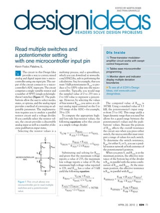
Figure 1 This circuit allows one R EFFMAX = EFFMIN SW + R ADJ + R BIAS R SW
R SW + R ADJ + R BIAS R SW + R BIAS
microcontroller pin to read multiple
VLOW × R ADJ R ADJ × (VHIGHVMAX ) × (R
R BIAS =
switches and edn100401di45911 DIANE
a potentiometer = R SW 3875V. + R BIAS )
= ADJ R × R BIAS
×THE ADJ × VLOW
R SW VMAX2+ R BIAS )
(R 4-8 FOLDER) EquMAX2SW × R= R
R3×V
Vation EFFMAX
u ; R EFFMIN = SW .
value. R HIGH SW + R ADJ + R BIAS
BIAS . Equation 4 R SW + R BIAS
=
R EFFMAX(PLACED IN ; R EFFMIN =
R SW + R ADJ + R BIAS Equation 4 R SW + R BIAS
Equation 3
u R SW × (R ADJ + R BIAS ) ×
R SW R R BIAS
Equation 4
R EFFMAX = EFFMIN =
; RV
S1MAX = R
EFFMAX.
Equation 4 VS1MAX =
R EFFMAX ADJ + R BIAS
R SW + R × VMAX . + R BIAS2010 × VMAX .71
April +
R EFFMAX22,R BIAS | EDN
SW
R EFFMAX + R BIAS
R SW × (R ADJ + R BIAS ) R × R BIAS
R = ;R = SW R EFFMAX .
2. R BIAS = = = 3875V.
VMAX2 × VLOW VMAX2 × VHIGH
designideas
Equation 3 SW × (R ADJ + R BIAS )
u
R EFFMAX =
R R
; R EFFMIN = SW
× R BIAS
.
Equation SW + R ADJ + R BIAS
u R3 R SW + R BIAS
R SW ×
R EFFMAX = value + R BIAS )
You determine the (R ADJ when you; R R SW × R BIAS
EFFMIN = .
Equation by evaluating R ADJ + R BIAS )
press S1 4 R SW + × (R ADJ + R BIAS
R SW the voltage di- R SW + R BIAS
R SW × R BIAS
viderR EFFMAX =and RRFFMAX form:R
that RBIAS R ; R EFFMIN = .
SW + R ADJ + BIAS R SW + R BIAS
Equation 4 R EFFMAX
VS1MAX = × VMAX .
R EFFMAX + R BIAS
Equation 4
Observe that when RADJ is at its max-
R EFFMAX
imum value and you press S1, it×must .
VS1MAX = VMAX
produce 5 R EFFMAX + R BIAS
Equation a value less R EFFMAX smallest
than the
VS = ×V .
value R1MAX R EFFMAX + toBIAS
ADJ
produces by itself R unique- MAX
ly determine that you have pressed the
Equation 5 R 2
switch. So the maximum effective re-
BIAS
sistance, <EFFMAX, must produce a value
R EFFMAXR
Equation BIAS + R ADJ
R 5
.
less than the maximum low voltage, as
the following equation shows:
R 2
R EFFMAX < BIAS .
Equation 6 + 2
R BIAS R R ADJ
R EFFMAX < BIAS .
R BIAS + R ADJ Figure 2 The circuit can have 10 pushbuttons and one potentiometer.
Equation 6 3 + R
Substituting and solving2this ADJ
R BIAS BIAS × R equation values is not necessary, it minimizes two pushbuttons, but the number of
R SW < switch resistance yields: .
for the the number of calculations you need pushbuttons can vary. Input ranges
Equation + 2 × R
2 6
R ADJ ADJ × R BIAS to perform and simplifies the design. are available for as many as 10 push-
3 2
R BIAS + R BIAS × R ADJ Furthermore, selecting smaller series buttons and one potentiometer, all of
R SW < 3 2
. switch resistors opens the guard range which share the same input pin (Fig-
2
R R BIAS ×+ R BIAS R× R ADJ between them and the potentiometer,
+ 2 R ADJ × BIAS ure 2). Although the computed rang-
R SW <ADJ .
R ADJ2 + 2 × R ADJ × R BIAS which may be desirable if the result- es do not overlap and are unique, it
Using the spreadsheet to compute ing values are too close together. The is doubtful that your ADC hardware
the switch resistance yields 1558V, microcontroller uses a small subrou- can reliably distinguish these bands
and you can choose a nominal 1.5- tine, Listing 1, which you can down- under all circumstances. Choosing
kV resistor. This selection causes S1 to load at www.edn.com/100422dia, to smaller resistor values keeps these
produce a range of 28 to 71 when you determine both switch positions and bands farther apart, creating a larger
press it, depending on the potentiom- the potentiometer’s setting. guard range.
eter’s position. Likewise, choosing the The limitation of this technique is Using this technique with four
same value for S2 produces a range of that you cannot press more than one pushbuttons and one potentiometer
184 to 227. These ranges are bands of pushbutton at any time. In addition, is well within reason. Experimenting
values that you can use to determine the microcontroller can read the po- with the spreadsheet helps make quick
which switch you pressed regardless tentiometer’s position only when you work of determining just the right se-
of the potentiometer’s position. Al- are not pressing any other pushbut- ries-resistor values for each switch and
though selecting symmetrical resistor tons. This example shows how to use its output range.EDN
Three-transistor modulator- tion is not important in these applica-
tions. When you drive a piezoelectric
amplifier circuit works load, its natural resonance removes any
frequency components other than the
with swept-control frequencies fundamental. This circuit combines a
modulator and an amplifier into a sin-
Horia-Nicolai L Teodorescu and Victor Cojocaru,
gle stage. The compactness of the cir-
Gheorghe Asachi Technical University, Iasi, Romania
cuit makes it appropriate for portable-
Many applications require a electric generator in a robot. Other ap- system applications.
circuit to perform pulse mod- plications include driving small motors The load is in series with two switch-
ulation and voltage amplification to or LEDs. Echolocation and ultrasound es (Figure 1). The input signal controls
drive a load with a train of impulses. A visualization use a sweeping-frequen- S2, S3 controls S1, and the modulating
typical application is driving a piezo- cy, or chirp, signal. Nonlinear distor- signal controls S3. This circuit’s mod-
72 EDN | April 22, 2010
3. designideas
ulation operation is similar to that of
an AND gate. The switches must have If the load imped-
RLOAD internal resistance to dissipate the har-
monics that the resonant load reflects.
ance varies, the
S3
This circuit uses transistors Q1 and Q2 circuit does
S1 as switches, although they operate in not degrade the
the active region (Figure 2). Their op-
eration resembles that of controlled re- impulse shape.
S2
sistors, and they perform voltage and
current amplification. You drive Q2
with a 42-kHz signal that matches the the state of Q2. Q1 and Q2 operate con-
load’s resonance. You modulate the Q3 jointly; Q1 conducts only when Q2 is
transistor with a periodic low-frequen- conducting. You can view this scheme
cy impulse signal. These impulses open as a differential amplifier in which the
Figure 1 This simple modulator Q3, which drives Q1 and Q2 toward sat- signal in one branch controls the load
uses three switches. uration. When Q3 opens, it drops the of another branch.
voltage across the base of Q1, blocking Q2 and Q3 operate over large signals
yet remain in the active region most of
the time. The resistor values in the base
MURATA
MA40B8R and collector of Q1 are critical. When
edn100401di46181 DIANE
the frequency of the signal is higher
THE 4-8L1
(PLACED IN 1 FOLDER)
2
than the load’s resonant frequency, D1
protects Q1 from the effects of L1 and
+
R1 25V dc of harmonics on the LC circuit. The
100 –
V1 collector voltage has a spectrum rich in
C1 R5
62F
R2 harmonics due to the nonlinear behav-
100 5k
ior of transistors. This characteristic is
R4
90k
not a serious disadvantage because the
2
resonant load removes the harmonics.
D1 The value of R1 is critical to the cur-
1 1N6392 Q1 rent and voltage amplification of the
BC516
Q1/Q2 stage. The swing of voltage in
Q2
the collector of Q1 is sensitive to the
BC517 R5
R5 value of R1 (Figure 3). Q1 operates in
100k 100k
the active mode because its collector
voltage increases slowly toward the
maximal value. The significant glitch
Q3
BC517 at small collector voltages shows that
the blocking process partly occurs in
the active regions of Q2 and Q3. If the
Figure 2 A three-transistor modulator with a resonant load works over a large load impedance varies, the circuit does
input range. not degrade the impulse shape. This
situation is true even at twice the load’s
resonant frequency. The circuit func-
tions with input voltages of 4.5 and
11V. This voltage range allows you to
drive the circuit with a 5V microcon-
troller (Reference 1).EDN
R e fe r e nce
1 Teodorescu, Horia-Nicolai L, “Algo-
rithm for Adaptive Distance Estima-
tors for Echolocation in Air,” Interna-
tional Solid-State Circuits Confer-
Figure 3 Changing the value of R1 yields different response waveforms. ence, 2009, www.adbiosonar.ugal.ro/
ad/content/funding.
74 EDN | April 22, 2010
4. designideas
When working with tables, you
Tables ease should always use indexed addressing
microcontroller programming mode. It provides access to data using
variable addresses. Most microcon-
trollers have two index registers, X and
Abel Raynus, Armatron International, Malden, MA
H. Register X contains the low byte of
When creating microcontroller the conditional address of the operand;
START
firmware, you often need to H contains the high byte. The algo-
work with data arrays. Tables make rithm of working with tables is straight-
CLEAR REGISTER X
easy work of data arrays, such as those CLEAR REGISTER H forward. After you detect the input
for digital-code transformation, correc- value, you should then compare it with
tion for sensor linearity, sophisticated GET THE INPUT VALUE, V the table’s input data. The X index de-
calculations, and multiple output orga- termines this value, starting with X50
nization. Table 1 shows how you can and ending with X5N. In this exam-
organize data in a table. Outputs A, B, V=VX?
YES
ple, N54. When you find table data
and C have values based on the input equal to the input value, you use the
NO
value, V. AX�REGISTER A corresponding X as an index to load the
When using a lookup table, choose X>N?
YES BX�REGISTER B output registers with their values. In the
CX�REGISTER C
the proper microcontroller input and case of 2-byte numbers, you should load
outputs. Assign values for input and NO
the output registers separately, first with
outputs data in Table 2. These data can INCREMENT X a high byte and then with a low one.
consist of constants in binary, hexadec- Figure 1 illustrates this process.
imal, or decimal format or names. For END The listing of assembler code is
names, you should assign a constant available from the online version of
value to each one. For example: this Design Idea at www.edn.com/
data1 equ $0a Figure 1 You can use a look-up table article/100422dib. In the listing, you
data2 equ $0b in microcontroller code. can double-check the table content
data3 equ $0c in memory at addresses $F800 through
data3 equ $0d ORG ROM $F813. The listing uses Freescale (www.
Next, put the data from Table 2 in ei- Vx FCB 0T,2T,4T,6T freescale.com) assembler because most
ther the beginning or the end of ROM, Ax FCB data1,data2,data3,data4 of the appropriate applications employ
which makes the data easy to find. For Bx FCB $aa,$bb,$cc,$dd inexpensive, 8-bit microcontrollers
edn100401di46341 DIANE
definition of 1-byte data storage, use Cx FDBTHE 4-8 FOLDER)
(PLACED IN $1122,$3344,$5566,$7788 from Freescale’s HC08 Nitron family.
pseudo operators FCB or DB. For stor- Note that commas separate the data. You can, however, use this approach
age of data comprising 2 bytes, use FDB Don’t place a comma after the last with any type of microcontroller and
or DW, as in the following example: data, or it will be considered as $00. assembly language.EDN
Table 1 Output values versus input values Table 2 Input and output values
Input V Output A Output B Output C Input V Output A Output B Output C
V1 A1 B1 C1 V1=0T data1 $aa $1122
V2 A2 B2 C2 V2=2T data2 $bb $3344
.... .... .... .... V3=4T data3 $cc $5566
VN AN BN CN V4=6T data4 $dd $7788
indication of both the direction and
Monitor alarm and indicator display the magnitude of the temperature’s de-
multiple deviation boundaries viation from a user-set mean in a sol-
der pot. Using a Microchip (www.mi-
crochip.com) 12F675 controller, the
William Grill, Riverhead Systems, Lenexa, KS
coded sequences allow the user to both
A low-cost monitor can visu- high- or low-temperature characteris- set the mean and scale the range of the
ally indicate a process problem, tic. The microcontroller-based circuit monitored variation. The application
such as a failed cabinet fan or other in Figure 1 provided a simple visual uses the controller’s internal clock and
76 EDN | April 22, 2010
5. designideas
two of the controller’s four ADCs. scaled boundaries to a corresponding quences of one or both LEDs. The
Asserting switch S1 on Pin 4 copies display format. The processor moni- monitor also asserts an output on Pin 5
the input voltage under test from Pin tors both the input under test and a when the measured variation exceeds
7, which becomes the mean value. The second analog level, on Pin 6, to scale the third tabled boundary.
code then evaluates the input-voltage the internal deviation/boundary tables. The circuit provides independent
deviation from the mean and applies It then schedules as many as four se- positive- and negative-deviation ta-
bles and multiplies the ranges by inter-
preting the voltage on Pin 6, resulting
10 �F
in the application of a multiple from
1N4148
7 TO 12V
one to eight on the boundary limits.
78L05
You configure the converter reference
4.7 �F 4.7k
1 8
to use the controller’s VDD voltage.
RED LED 470 Using only 8 bits of the controller’s
7 2
PARAMETER/VOLTAGE UNDER TEST
12F675
10-bit ADC, the deviation can be as
6 3 470
SCALER-SET VOLTAGE small as one step or 1/2563VDD, the
GREEN LED 470
4.7k 4 5 drain-to-drain voltage. For a 5V ref-
ALARM/ERROR erence, this voltage is approximately
S1
SET MEAN
RED LED 9 mV.
Figure 2 shows the boundaries and
their possible spans, which Pin 6 and
corresponding display-format num-
bers set (Table 1). Using the provid-
Figure 1 This microcontroller-based circuit provides a simple visual indication of ed minimum value of the deviation/
both the direction and the magnitude of the temperature’s deviation from a user- boundary table, neglecting the error
set mean in a solder pot. that results from the use of the 78L05
as a reference, and assuming the scal-
edn100401di46321 DIANE
(PLACED IN THE 4-8 FOLDER)
78 EDN | April 22, 2010
6. MEAN SETPOINT
Table 1 Display-format
�1 (DERIVED FROM PIN 6) numbers and table-based
sequence
DISPLAY-FORMAT
�5 �4 �3 �2 �1 1 2 3 4 5 NUMBER Display-format
20 14 9 5 2 2 5 9 14 20 DEVIATION/ number Sequence
BOUNDARY COUNT �1
ADC-BIT DEVIATION FROM MEASURED VALUE TO MEAN >5 Green, red/green,
PIN 5 ALARM OUTPUT
red/green, red/green
5 Green, green, green/red,
green/red
Figure 2 Pin 6 and the corresponding display-format numbers set the boundar-
4 Green, red, green/red
ies and their possible spans.
3 Green, green, green, red
ing derived from Pin 6 result in 31, no/go applications or other needs. The 2 Green, green, red
the first display-format step, in this ap- circuit may also find a use in airflow or 1 Green
plication, which occurs when the mea- other physical-parameter monitors.
21 Red
sured input deviates more than the de- Using the controller’s ADC, you
viation/boundary-table value times the can monitor any parameter that you 22 Red, red, green
scale derived from Pin 6 times 1/256 can represent with a voltage. You can 23 Red, red, red, green
times the drain-to-drain voltage equals modify the code-based tables to ac-
24 Red, green, red/green
235/25631, or 39 mV. commodate a variety of other display
You can change the display-sequence sequences, parameter nonlinearities, or 25 Red, red, red/green,
formats for the five positive boundaries, error distributions. red/green
beginning in a green-LED flash, and You can download Listing 1, code ,,<< <5 Red, red/green,
five negative boundaries, beginning in for the error monitor, from www.edn. red/greeen, red/green
a red-LED flash, to suit simpler go or com/100422dic.EDN
April 22, 2010 | EDN 79