SlideShare a Scribd company logo
1 of 5
Download to read offline
Suzuki DT90 & DT100 OUTBOARD MOTOR
SUZUKI
DT90 AND DT100
CONDENSED SERVICE DATA
NOTE: Metric fasteners nre used throughout outboard motor.
TUNE-UP
IIp/rpm:
DT90 ... . .. . .... . . .. . . . ... .. . . ..... 90/5000-5600
DTlOO . . .. . . . .. . . . .... 100/5000-5600
Bore . ......... . . . . . . ............... 84 mm
Stroke
(:3.31 in.)
. . . ....... 64 mm
(2.52 in.)
.. .. . . ..... ... ... .4Number of Cylinders .
Displacement . .. .... 1419 cc
(86.6 cu. in.)
. .. ... .. . .......... NGK BRSIIS-IO
.O.!H.O mm
(0.035·0.0:39 in.)
.Suzuki Microlink
. ... .Mikuni
Spark Plug
Electrode Gap.
Ignition Type
Carburetor Make
SIZES-CLEARANCES
Piston Ring End Gap:
Standard ....
Wear Limit
Standard Piston Diameter
.0.20-0.40 mm
(0.008-0.016 in.)
... . . ............ .0.80 mm
(0.031 in.)
.83.865·8:3.880 mm
(3.3018-:3.:3024 in .)
Standard Cylinder Diameter . ..... .. 84.000-84.015 mm
(:3.:3071-3.3077 in.)
Piston·to-Cylinder Clearance:
Standard. . . . .. .. ... . ... 0.12-0.15 mm
Wear Limit ..
Piston Pin Diameter:
Standard
Wear Limit ..
Piston Pin Bore Diameter:
Standard .....
Wear Limit ...
(0.005-0.006 in.)
. .. 0.22 mm
(0.0087 in.)
. 19.9%-20.000 mm
(0.7872-0.7874 in.)
.. .. 19.980 mm
(0.7866 in.)
.. .20.002·20.010 mm
(0.787,5-0.7878 in.)
..... . .. 20.030 mm
(0.7886 in.)
Max. Allowable Crankshaft Runout at
Main Bearing .Journal ...... .
Max. Allowable Connecting Rod Small
End Side Shake
. .... 0.05 mm
(0.002 in.)
. ...... .5.0 mm
(0.20 in.)
TIGHTENING TORQUES
Cylinder Head Cover: . ... .. ...... ....... 8-12 N'm
Cylinder Head ...... . ... .
Cylinders ...... ... . . . . .. .. . . ..... .
(iI-106 in .-Ibs.)
.... 28-32 N'm
(21-24 ft.-Ibs.)
... 46-54 N'm
(34-40 ft.·lbs.)
Exhaust Cover .. .
Flywheel Nut
...... ... 8-12 N'm
(71-106 in.-Ibs.)
.250-260 N'm
(184-192 ft.-lbs.)
Gearcase Pinion Nut. . . . . . . . . .. . . . . . .. 80-100 N'm
Propeller Shaft Nut
(59-7:3 fUbs.)
. .50-62 N'm
Water Pump Housing ......... .. . . .
(37-45 ft.-Ibs.)
. 15-20 N'm
(11-14 ft.-Ibs.)
Standard Screws:
Unmarked or Marked " 4"
!'imm .... . ...... . ....... 2-4 N'm
(18·:35 in.-Ibs.)
6 mm ..... . ...... . .. . .. .. . .. . . . . ... .4-7N·m
(:35-62 in.-Ibs.)
.... .... 10·16 N'm
(88-141 in.-Ibs.)
8111111 ... . ... • ••.
10 mm .... . .. .... . . . .. ... .. .. . . . . .. 22-35 N'm
(16-25 ft.·lbs.)
Stainless Steel
5 mm .. ... .
6 nun . ..
8 mill ..... .. . . . . . . . . . . . .. . . . . .. .
.2-4 N'm
(18-35 in.-Ibs.)
.6-10 N'm
(5:3-88 in.-lbs.)
..... 15-20 N'm
(11-14 fUbs.)
.... :34-41 N'm
(25-30 ft.-lbs.)
10 mm ........ .
Marked "7":
5 mm
6 mm .
8 mill ....
10 mm .. ... . .
.. ...... 3-6 N'm
(26-5:3 in.-Ibs.)
..... 8-12 N'm
(71-106 in.-Ibs.)
... . .. ... 18-20 N'm
(13·14 fUbs.)
.... .40-60 N'm
(29-44 ft.-Ibs.)
LUBRICATION
The power head is lubricated by oil
mixed with the fu el. All models are
equipped with oil iljection. The recom-
mended oil is Suzuki Outboard Motor Oil
or a suitable equivalent NMMA certified
TC-WII engine oil. The recommended
fuel is unleaded gasoline with a mini-
mum pump oclane rating of 85.
ensure adequate engine lubrication. Af·
ter break-in period, switch to straight
gasoline in the fu el tank.
During break-in (first five hours of op-
eration), a 50; 1 fuel and oil mixture
should be used in the fuel tank in com-
bination with the oil iljection system to
The lower unit gears and bearings are
lubricated by oil contained in the gear-
case. The recommended oil is Suzuki
Outboard Motor Gear Oil or a good qual-
SERVICE MANUAL
ity SAE flO hypoid gear lubricalll. Gear-
case capacity is ~GO mL (l8.fl fl. oz.). The
gearca.-;e oil should be changed after the
first to hours of operation and every toO
hours thereafter.
FUEL SYSTEM
CARBURETOR. ~likuni BW:l6-24 car-
buretors are used on Model 011)0 and
Mikuni 3W40-:32 carburetor.; are used on
Model DTIOO. Two carburetor.; are used
on all models. l{efer to Fig. SZ18-1 for ex-
ploded view.
Standard main jet (12) size for normal
service is 111:32.;5 on D1WJ models and
#165 on DTlOO nlOdds. Standard pilotjN
(6) size for normal service is 1190 on m1l0
models and !i77.5 on m'lOO models.
Th check float le'e1, remo'e float bowl
and invert carburetol: Distance (D-Fig.
SZI8-2) between bottom of float: and
float bowl mating surface on carbure·
tor body should be 9.~-ll.ij mm (0.:37-
0.45 in.). Carefully bend rang on float
arm to adjust.
Initial selling of pilot air screw (3-
Fig. SZI8-1) from a lightly seated posi-
tion is I',. to I". turns. Final adjustment
should be pcrfonncd with engine at nor-
mal operating temperature, running in
forward gear. Adjust idle speed switch
(on lower engine cover) to obtain 600-
650 rpm in forward gear. Adjust pilot
screw (3) so engine idles smoothly and
will accelerate cleanly without hesi-
tation.
NOTE: II unabte to obtain 600·650 rpm in
lorward gear, adjust throttle stop screw on
top carburetor as necessary or check adjust·
ment 01 throttle valve sensor (2). ReIer to
IGNITION section.
FUEL PUMP, A diaphragm type fu el
pump is usee!. Fuel pump is mounted on
the power head and is actuated by
crankcase pulsations. I{efer to Fig. SZI8-
4 for an exploded view of pump as-
sembly.
Inspect diaphragms (2 and 4) for
cracking, detelioration or other damage.
Defective or questionable components
should be renewed. Match marks are
provided on cover (I) and body (:1) for
correct alignment during reassembly.
Tighten cover screws evenly in a cross-
ing pattern.
FUEL FILTER. A fuel fill er (Fig.
SZI8-4) is mounted on th.. power head.
Filter should be di!;&isembled to inspect
element (12) every 50 hours of opera-
tion. Clean clement in a suitable sol-
·enl. Renew element of excessive block-
age is noted.
REED VALVES. The inlet reed valves
are located on a V-shaped reed plate be-
tween int,lke manifold and cranke-ase.
Refer to Fig. SZI8·5. The reed petals
should seat very lightly against the reed
plate throughout their entire length
with the le,L<;t possihle tension. Renew
reeds if tip of reed petal stands open
more than 0.2 mm (O.OOS in .) from con-
tact surface. Reed stop opening should
be 10.5 mm (0.413 in.) as shown in Fig.
SZIS-7.
[{enew reeds if petals are broken,
eracked, warped, rllsted or bent. Never
attempt to bend a reed petal or straight-
en a damaged reed. Never install a bent
or damaged reed. Seating s1ll1-ac:e of
reed plate should be smooth and flat.
When installing reeds or reed stop, make
sure that petals are centered over the
inlet ports in reed plate, anti that reed
stops are centered over reed petals. Ap-
ply Suzuki Thread Lock 1:342 ora suita-
ble equivalent thread locking compound
to threads of reed stop screws during
reassembly. Install reed vain! assemblies
i.o intake manifold with alTow embossed
on inside of reed plate (on one end) fac-
ing toward outside of engine.
SPEED CONTROL LINKAGE. '11>
synchronize carburetor throttle valves.
loosen two screws (S-Fjg. SZI8-8) on
top earburetor throttle lever (L). Rotate
lever (L) clockwise until throttle v<llves
are eompletely closed, then retighten
screws (S). Be sure throttle valves open
and dose at exactly the same time. With
remote control in the neutral position,
loosen jam nuts (N-Fig. SZIS-9) and ad-
just lengt.h of rod (I) so a c:icarance of
Fig. SZIS-4-Exploded view
of fuel pump and fuel filter as-
sembly.
I C,I'l'r
:!. 1"}I j)phm~1Il
;j !-)dy
.1. U'iiJ ,h F1.Ijl.1I1
.j SI}l'"i lllol,
,; 11)111''' pbl~'
. , " 0" rinj(
K . ~hl1
~ I W".,ht'r
(I F,hl'r b..",-
11. Pt1ckin"
I:! FIJkr .-,I.·IIwnl
I:l . " 0" rloil.
If CIII'
Suzuki 0190 & 01100
Fig. SZI8-1-Exploded view of carburetors used
on all modelS.
Hood'
Thr;,n k· ';iln:
S('tl.$lI f"
:) Pilot ~·rt.".,
·1. Inll~t  '.1' 1' 1: ".':11
I~in
(i . rUt" Jet
I. Jo'U;'l1
k 1I 1~~1 ~I )O!.~,1 "!lui...."
!I lif';."1
ill :1111 j"t 1I"ld';:r
II GiJ..s)WI
I i. ) l:dnJl'b
I:;. fin,-u bllwl
,.1. I.in'c rod
Fig. SZIS·2-Floal height (D) should be 9.5· I 1.5
mm (0.37-0.45 in.). Bend lang on float arm to
ad/usl.
Suzuki DT90 & 01100
I mm (OJH in.) is present between throt-
tle lever (.~) and stopper (5) on carbure-
tor. Refer 10 OIL IN.JECTION section for
iqjeLtion pump control linkage ad-
justment.
Fig. SZI8-6-Exploded view of intake manifold
and reed valve Bssemblles.
1 InUtkc rn:inlfold
2. CiiI.S).;.'-l
:3 Hced pau~
10.5mm (0.413 In.)
<1 H('l'd p(-l:,lb
:;. H('('d st(Jp
Fig. SZI8-7-Dls/Mce belween reed slap (5) and
reed plale (3) should be 10.5 mm (0.413 In.) ss
shown. CleafsnC6 between reed petal (4) Bnd reed
plele (3) musl not exceed 0.2 mm (0.008 In.).
R--~
Fig. SZ18-8-Refer to text to synchronize carbu-
retor thronle valves.
To ease engine stalting, ignition lim-
ing is electronically advanced to 5 de-
grees BTDC. The starting ignition ad-
vance duration is 15 seconds when
engine temperature is below 87°-1100 C
(:36°-44° F) and 5 seconds when enb'ine
is warmed to 97°-110° C (3(j0-44° F) or
above. After the initial timing advance
period. idle speed timing is controlled
by thp. idle speed adjustment switch.
The idle speed acljustment switch varies
timing from 7 degrees ATDC (slow) to
TDC (fast), changing idle speed approx-
imately 50 rpm per position.
Full throttle timing should be 2:3 de-
grees BTDC at 5000 rpm and is electron-
ically controlled by the Micro Link pro-
cessor. The processor uses information
from the gear counter coil and the throt-
tle valve sensor to determine the opti-
mum ignition timing for all operating
conditions. Hefer to IGNITION section
for throttle ,·alve sensor acljustment
procedure.
OIL INJECTION
BLEEDING PUMP. Air should be
purged from irjection system any time
an irljection system component has been
removed or renewed, or if outboard mo-
tor has been in storage.
While bleeding the system, a 50:1 fuel
and oil mixture must be used in the fuel
tank to ensure proper engine lubrication
during the bleeding procedure. Open
the air bleed screw (B-Fig. SZIH-Il) two
or three turns. Start engine and run at
MiO-700 rpm until air is no longer noted
at screw (n). Stop engine and tighten
screw (il) securely.
CHECKING OIL PUMP OUTPUT.
Start engine and warm-up for approxi-
mately five minutes. Stop engine. re-
move oil reservoir and disconnect oil
pump control rod (2-Fig. SZIS-Il) from
carbureto!: Connect Suzuki oil measur-
ing cylinder 08!J4HiH7!O to oil pump in-
let hose and fill with a recommended
engine oiL l3Ieed air from system as
previously outlined, then refill oil cyl-
inder to an upper reference mark. Ho-
tate oil pump control lever to the fully
closed (clockwise) position, start engine
and run at 1500 rpm for exactly five
1mm ro.cw in)';~;:~?
OUTBOARD MOTOR
minutes. After five minutes. slop engine
and note oil mea.,uring cylinder. Oil con-
sumption in five minutes at 1500 rpm
should be 2.5-4.5 mL (OJ)H5-0.152 fl. oz.).
Next. refill oil cylinder, rotate oil
pump control lever to the full-open
(counterclockwise) position, start en-
gine and run at 1500 rpm for exactly two
minutes. Stop engine and note oil cyl-
imler. Oil consumption in two minutes
at 1500 rpm should be (j.O-8.0 mL (0.203-
0.:304 fl. oz.). After reconnecting oil
pump control rod to carburetOl; be sure
carburetor throttle valves are properly
synchronized (SPEED CONTHOL LiNK-
AGE) and check acljustment of oil pump
control rod as outlined in PUMP CON-
TROL ROD ADJUSTMENT section.
NOTE: 011 pump output test results may
vary depending on testing error and ambient
temperature. To ensure accurate results, re-
peat test three times, or until results are
consistent.
Renew oil pump assembly (I) if out-
put is not as specified.
Be sure pump is properly engaged
with driven gear (:3) before tightening
fasteners.
OIL FLOW SENSOR. Oililow sensor
(9-Fig. SZIS-II) is connected in-line be-
tween oil reservoir and oil pump. The
oil flow sensor serves as an oil filter as
well a.g a sensor to detect insufficient oil
flow to pump. Should oil flow become
restricted, the sensor circuit closes, sig-
naling the microcomputer to decrea.,e
engine speed and activate the warning
lamp and buzzer.
The sensor filter should be periodical-
ly removed and cleaned in a SUitable sol-
vent. Henew filter if excessive blockage
is noted.
Tb test sensor. connect an ohmmeter
between sensor pinklblue wire and
black wire. No continuity should be
present. Next. plug sensor inlet and ap-
ply a vacuum to the outlet port. Zero
ohms should be noted with vacuum
applied.
PUMP CONTROL ROD ADJUST-
MENT. Make sure carburetor throttle
Fig. SZI8-9-VIew ofthrottle
linkage on all models.
I Link roo
1.. ThTOftl(' ann
3. Curhuret.or
4. Throttle I(''~'r
5. S(t)PrK'r
S . luu
SERVICE MANUAL
valves are properly synchronized as de-
scribed in SPEED CONTROL LINKAGE
section. With throttle in the fully closed
position, clearance (C-Fig. SZIS-12) be-
tween boss (4) and control lever (3)
should be less than 1.0 nlIn (0.0:,9 in.),
but lever (3) should not be touching boss
(4). Loosen nuts jam nuts (N) and vary
length of rod (2) to adjust.
IGNITION
All models are equipped with Suzuki
Micro Link ignition system. 1Ilicro Link
is comprised of a capacitor discharge ig-
nition system (CDl) and a microcom-
puter. The microcomputer processes in-
formation from various sensors and
switches including throttle valve open-
ing, engine rpm and shift lever position,
then determines the optimum ignition
timing. The ]llicro Link system also mon-
itors oil level, oil flow, water flow and
overspeed caution systems. If one or
more eaution systems indicate a mal-
function, the microcomputer activates
the appropriate warning buzzer and
lamp, and reduees engine speed to a
predetermined level.
TROUBLE-SHOOTING. Test ignition
system using Stevens 1I10dei CD-77 or a
suitable equivalent peak reading volt-
meter (PRV) and Suzuki Pocket Tester
09900-25002 or a suitable equivalent
ohmmeter. Refer to Figs. SZIS-14 and
SZIS-L3.
1b check ignition system peak voltage,
remove spark plugs, and refer to chart
in Fig. SZIS-16. Output is measured at
cranking speed only. Make sure battery
is fully charged and in good condition.
If peak voltage is less than specified in
chart, renew component being tested.
If testing ignition components using
Suzuki Pocket '!ester 09900-25002, or an
ohmmeter, refer to Figs. SZIS-14 and
SZIS-15 and proceed as follows:
COlDENSER ClIARGE COIL. Discon-
nect six-pin connector (Fig. SZIS-15)
leading from stator plate. Connect ohm-
meter between the black/red terminal
and the green terminal. Resistance
should be 180-270 ohms.
PULSER COILS. Disconnect the six-
pin connector leading from stator plate.
Connect tester between engine ground
and alternately to the red/green,
white/black, red/white and white/green
terminals. Resistance at each terminal
should be 160-230 ohms.
Air gap between pulser coils and the
flywheel should he 0.7!; mm (0.029 in.).
The manufacturer recommends using
Suzuki pulser eoil IDeating tool (part
09931-88710) to properly position puls-
er coils.
GEAR COUNTER COIL. Unplug con-
nectors leading from gear counter coil
(8-Fig. SZIS-15). Connect tester be-
tween the orange/green and the
black!green wire eonneetors. Resistance
should be 160-230 ohms.
Air gap between counter coil and the
flywheel ring gear teeth should be 0.5
mm (0.020 in.). Loosen counter coil
mounting screws and slide coils as
necessary to adjust.
Fig. SZI8-11-Exploded vIew
of all Injection pump and re-
lated components.
pnnp ~~'.
(';om rol rod
:1. DIi'('n "War
-1. G~k('l
R~'UlITl~ r
"0" ring
A ir/nil niixlnp; "~Il','
H Ch('(:k '1.Llv('
o. ()j[ fI()w s(:nsqr
L'I lllt'l'd Ii(;n' .....
Fig. SZI8·12-Refer to text
for all pump control rod ad-
Justment procedure.
Pump i;L'!iy
C.onlrol rod
:3 G<Jn l TI1 1 it.''(,'r
1. &$:.1
~ ,J(,m nuts
Suzuki OT90 & OT100
BATTERY CHARGE COILS. Unplug
the yellow and red wire connectors and
connect tester between the two connec-
tors. Resistance should be 0.4-0.6 ohm.
Note that checking resistance between
the yellow and red wires tests resistance
of both battery charge coils.
IGNITION COILS. Ignition coil primary
winding resistance should be 0.15-0.25
ohm. Connect tester between black and
carburetor
•
Hello
Thank you very much
for your patience.
At the bottom of the
page there is a FREE
ADD TO CART button.
Click on it and you will
get zip file on the bottom
Please click here.
Go back to the page.
of the page.

More Related Content

Recently uploaded

Call me @ 9892124323 Call Girl in Andheri East With Free Home Delivery
Call me @ 9892124323 Call Girl in Andheri East With Free Home DeliveryCall me @ 9892124323 Call Girl in Andheri East With Free Home Delivery
Call me @ 9892124323 Call Girl in Andheri East With Free Home DeliveryPooja Nehwal
 
Delhi Call Girls Vikaspuri 9711199171 ☎✔👌✔ Whatsapp Hard And Sexy Vip Call
Delhi Call Girls Vikaspuri 9711199171 ☎✔👌✔ Whatsapp Hard And Sexy Vip CallDelhi Call Girls Vikaspuri 9711199171 ☎✔👌✔ Whatsapp Hard And Sexy Vip Call
Delhi Call Girls Vikaspuri 9711199171 ☎✔👌✔ Whatsapp Hard And Sexy Vip Callshivangimorya083
 
Vip Hot Call Girls 🫤 Mahipalpur ➡️ 9711199171 ➡️ Delhi 🫦 Whatsapp Number
Vip Hot Call Girls 🫤 Mahipalpur ➡️ 9711199171 ➡️ Delhi 🫦 Whatsapp NumberVip Hot Call Girls 🫤 Mahipalpur ➡️ 9711199171 ➡️ Delhi 🫦 Whatsapp Number
Vip Hot Call Girls 🫤 Mahipalpur ➡️ 9711199171 ➡️ Delhi 🫦 Whatsapp Numberkumarajju5765
 
Chapter-1.3-Four-Basic-Computer-periods.pptx
Chapter-1.3-Four-Basic-Computer-periods.pptxChapter-1.3-Four-Basic-Computer-periods.pptx
Chapter-1.3-Four-Basic-Computer-periods.pptxAnjieVillarba1
 
Hauz Khas Call Girls ☎ 7042364481 independent Escorts Service in delhi
Hauz Khas Call Girls ☎ 7042364481 independent Escorts Service in delhiHauz Khas Call Girls ☎ 7042364481 independent Escorts Service in delhi
Hauz Khas Call Girls ☎ 7042364481 independent Escorts Service in delhiHot Call Girls In Sector 58 (Noida)
 
Vip Hot🥵 Call Girls Delhi Delhi {9711199012} Avni Thakur 🧡😘 High Profile Girls
Vip Hot🥵 Call Girls Delhi Delhi {9711199012} Avni Thakur 🧡😘 High Profile GirlsVip Hot🥵 Call Girls Delhi Delhi {9711199012} Avni Thakur 🧡😘 High Profile Girls
Vip Hot🥵 Call Girls Delhi Delhi {9711199012} Avni Thakur 🧡😘 High Profile Girlsshivangimorya083
 
FULL ENJOY - 9953040155 Call Girls in Sector 61 | Noida
FULL ENJOY - 9953040155 Call Girls in Sector 61 | NoidaFULL ENJOY - 9953040155 Call Girls in Sector 61 | Noida
FULL ENJOY - 9953040155 Call Girls in Sector 61 | NoidaMalviyaNagarCallGirl
 
꧁ ୨ Call Girls In Radisson Blu Plaza Delhi Airport, New Delhi ❀7042364481❀ Es...
꧁ ୨ Call Girls In Radisson Blu Plaza Delhi Airport, New Delhi ❀7042364481❀ Es...꧁ ୨ Call Girls In Radisson Blu Plaza Delhi Airport, New Delhi ❀7042364481❀ Es...
꧁ ୨ Call Girls In Radisson Blu Plaza Delhi Airport, New Delhi ❀7042364481❀ Es...Hot Call Girls In Sector 58 (Noida)
 
Call Girls in Malviya Nagar Delhi 💯 Call Us 🔝9205541914 🔝( Delhi) Escorts Ser...
Call Girls in Malviya Nagar Delhi 💯 Call Us 🔝9205541914 🔝( Delhi) Escorts Ser...Call Girls in Malviya Nagar Delhi 💯 Call Us 🔝9205541914 🔝( Delhi) Escorts Ser...
Call Girls in Malviya Nagar Delhi 💯 Call Us 🔝9205541914 🔝( Delhi) Escorts Ser...Delhi Call girls
 
How To Fix Mercedes Benz Anti-Theft Protection Activation Issue
How To Fix Mercedes Benz Anti-Theft Protection Activation IssueHow To Fix Mercedes Benz Anti-Theft Protection Activation Issue
How To Fix Mercedes Benz Anti-Theft Protection Activation IssueTerry Sayther Automotive
 
Alina 7042364481 Call Girls Service Pochanpur Colony - independent Pochanpur ...
Alina 7042364481 Call Girls Service Pochanpur Colony - independent Pochanpur ...Alina 7042364481 Call Girls Service Pochanpur Colony - independent Pochanpur ...
Alina 7042364481 Call Girls Service Pochanpur Colony - independent Pochanpur ...Hot Call Girls In Sector 58 (Noida)
 
Innovating Manufacturing with CNC Technology
Innovating Manufacturing with CNC TechnologyInnovating Manufacturing with CNC Technology
Innovating Manufacturing with CNC Technologyquickpartslimitlessm
 
Lucknow 💋 (Genuine) Escort Service Lucknow | Service-oriented sexy call girls...
Lucknow 💋 (Genuine) Escort Service Lucknow | Service-oriented sexy call girls...Lucknow 💋 (Genuine) Escort Service Lucknow | Service-oriented sexy call girls...
Lucknow 💋 (Genuine) Escort Service Lucknow | Service-oriented sexy call girls...anilsa9823
 
83778-77756 ( HER.SELF ) Brings Call Girls In Laxmi Nagar
83778-77756 ( HER.SELF ) Brings Call Girls In Laxmi Nagar83778-77756 ( HER.SELF ) Brings Call Girls In Laxmi Nagar
83778-77756 ( HER.SELF ) Brings Call Girls In Laxmi Nagardollysharma2066
 
(COD) ̄Young Call Girls In Dwarka , New Delhi꧁❤ 7042364481❤꧂ Escorts Service i...
(COD) ̄Young Call Girls In Dwarka , New Delhi꧁❤ 7042364481❤꧂ Escorts Service i...(COD) ̄Young Call Girls In Dwarka , New Delhi꧁❤ 7042364481❤꧂ Escorts Service i...
(COD) ̄Young Call Girls In Dwarka , New Delhi꧁❤ 7042364481❤꧂ Escorts Service i...Hot Call Girls In Sector 58 (Noida)
 
John Deere Tractors 6130M 6140M Diagnostic Manual
John Deere Tractors  6130M 6140M Diagnostic ManualJohn Deere Tractors  6130M 6140M Diagnostic Manual
John Deere Tractors 6130M 6140M Diagnostic ManualExcavator
 
John Deere 7430 7530 Tractors Diagnostic Service Manual W.pdf
John Deere 7430 7530 Tractors Diagnostic Service Manual W.pdfJohn Deere 7430 7530 Tractors Diagnostic Service Manual W.pdf
John Deere 7430 7530 Tractors Diagnostic Service Manual W.pdfExcavator
 

Recently uploaded (20)

Call Girls In Kirti Nagar 📱 9999965857 🤩 Delhi 🫦 HOT AND SEXY VVIP 🍎 SERVICE
Call Girls In Kirti Nagar 📱  9999965857  🤩 Delhi 🫦 HOT AND SEXY VVIP 🍎 SERVICECall Girls In Kirti Nagar 📱  9999965857  🤩 Delhi 🫦 HOT AND SEXY VVIP 🍎 SERVICE
Call Girls In Kirti Nagar 📱 9999965857 🤩 Delhi 🫦 HOT AND SEXY VVIP 🍎 SERVICE
 
Call me @ 9892124323 Call Girl in Andheri East With Free Home Delivery
Call me @ 9892124323 Call Girl in Andheri East With Free Home DeliveryCall me @ 9892124323 Call Girl in Andheri East With Free Home Delivery
Call me @ 9892124323 Call Girl in Andheri East With Free Home Delivery
 
Delhi Call Girls Vikaspuri 9711199171 ☎✔👌✔ Whatsapp Hard And Sexy Vip Call
Delhi Call Girls Vikaspuri 9711199171 ☎✔👌✔ Whatsapp Hard And Sexy Vip CallDelhi Call Girls Vikaspuri 9711199171 ☎✔👌✔ Whatsapp Hard And Sexy Vip Call
Delhi Call Girls Vikaspuri 9711199171 ☎✔👌✔ Whatsapp Hard And Sexy Vip Call
 
Call Girls in Shri Niwas Puri Delhi 💯Call Us 🔝9953056974🔝
Call Girls in  Shri Niwas Puri  Delhi 💯Call Us 🔝9953056974🔝Call Girls in  Shri Niwas Puri  Delhi 💯Call Us 🔝9953056974🔝
Call Girls in Shri Niwas Puri Delhi 💯Call Us 🔝9953056974🔝
 
Vip Hot Call Girls 🫤 Mahipalpur ➡️ 9711199171 ➡️ Delhi 🫦 Whatsapp Number
Vip Hot Call Girls 🫤 Mahipalpur ➡️ 9711199171 ➡️ Delhi 🫦 Whatsapp NumberVip Hot Call Girls 🫤 Mahipalpur ➡️ 9711199171 ➡️ Delhi 🫦 Whatsapp Number
Vip Hot Call Girls 🫤 Mahipalpur ➡️ 9711199171 ➡️ Delhi 🫦 Whatsapp Number
 
Chapter-1.3-Four-Basic-Computer-periods.pptx
Chapter-1.3-Four-Basic-Computer-periods.pptxChapter-1.3-Four-Basic-Computer-periods.pptx
Chapter-1.3-Four-Basic-Computer-periods.pptx
 
Hauz Khas Call Girls ☎ 7042364481 independent Escorts Service in delhi
Hauz Khas Call Girls ☎ 7042364481 independent Escorts Service in delhiHauz Khas Call Girls ☎ 7042364481 independent Escorts Service in delhi
Hauz Khas Call Girls ☎ 7042364481 independent Escorts Service in delhi
 
Vip Hot🥵 Call Girls Delhi Delhi {9711199012} Avni Thakur 🧡😘 High Profile Girls
Vip Hot🥵 Call Girls Delhi Delhi {9711199012} Avni Thakur 🧡😘 High Profile GirlsVip Hot🥵 Call Girls Delhi Delhi {9711199012} Avni Thakur 🧡😘 High Profile Girls
Vip Hot🥵 Call Girls Delhi Delhi {9711199012} Avni Thakur 🧡😘 High Profile Girls
 
FULL ENJOY - 9953040155 Call Girls in Sector 61 | Noida
FULL ENJOY - 9953040155 Call Girls in Sector 61 | NoidaFULL ENJOY - 9953040155 Call Girls in Sector 61 | Noida
FULL ENJOY - 9953040155 Call Girls in Sector 61 | Noida
 
꧁ ୨ Call Girls In Radisson Blu Plaza Delhi Airport, New Delhi ❀7042364481❀ Es...
꧁ ୨ Call Girls In Radisson Blu Plaza Delhi Airport, New Delhi ❀7042364481❀ Es...꧁ ୨ Call Girls In Radisson Blu Plaza Delhi Airport, New Delhi ❀7042364481❀ Es...
꧁ ୨ Call Girls In Radisson Blu Plaza Delhi Airport, New Delhi ❀7042364481❀ Es...
 
Call Girls in Malviya Nagar Delhi 💯 Call Us 🔝9205541914 🔝( Delhi) Escorts Ser...
Call Girls in Malviya Nagar Delhi 💯 Call Us 🔝9205541914 🔝( Delhi) Escorts Ser...Call Girls in Malviya Nagar Delhi 💯 Call Us 🔝9205541914 🔝( Delhi) Escorts Ser...
Call Girls in Malviya Nagar Delhi 💯 Call Us 🔝9205541914 🔝( Delhi) Escorts Ser...
 
How To Fix Mercedes Benz Anti-Theft Protection Activation Issue
How To Fix Mercedes Benz Anti-Theft Protection Activation IssueHow To Fix Mercedes Benz Anti-Theft Protection Activation Issue
How To Fix Mercedes Benz Anti-Theft Protection Activation Issue
 
Alina 7042364481 Call Girls Service Pochanpur Colony - independent Pochanpur ...
Alina 7042364481 Call Girls Service Pochanpur Colony - independent Pochanpur ...Alina 7042364481 Call Girls Service Pochanpur Colony - independent Pochanpur ...
Alina 7042364481 Call Girls Service Pochanpur Colony - independent Pochanpur ...
 
Innovating Manufacturing with CNC Technology
Innovating Manufacturing with CNC TechnologyInnovating Manufacturing with CNC Technology
Innovating Manufacturing with CNC Technology
 
Lucknow 💋 (Genuine) Escort Service Lucknow | Service-oriented sexy call girls...
Lucknow 💋 (Genuine) Escort Service Lucknow | Service-oriented sexy call girls...Lucknow 💋 (Genuine) Escort Service Lucknow | Service-oriented sexy call girls...
Lucknow 💋 (Genuine) Escort Service Lucknow | Service-oriented sexy call girls...
 
83778-77756 ( HER.SELF ) Brings Call Girls In Laxmi Nagar
83778-77756 ( HER.SELF ) Brings Call Girls In Laxmi Nagar83778-77756 ( HER.SELF ) Brings Call Girls In Laxmi Nagar
83778-77756 ( HER.SELF ) Brings Call Girls In Laxmi Nagar
 
(COD) ̄Young Call Girls In Dwarka , New Delhi꧁❤ 7042364481❤꧂ Escorts Service i...
(COD) ̄Young Call Girls In Dwarka , New Delhi꧁❤ 7042364481❤꧂ Escorts Service i...(COD) ̄Young Call Girls In Dwarka , New Delhi꧁❤ 7042364481❤꧂ Escorts Service i...
(COD) ̄Young Call Girls In Dwarka , New Delhi꧁❤ 7042364481❤꧂ Escorts Service i...
 
John Deere Tractors 6130M 6140M Diagnostic Manual
John Deere Tractors  6130M 6140M Diagnostic ManualJohn Deere Tractors  6130M 6140M Diagnostic Manual
John Deere Tractors 6130M 6140M Diagnostic Manual
 
John Deere 7430 7530 Tractors Diagnostic Service Manual W.pdf
John Deere 7430 7530 Tractors Diagnostic Service Manual W.pdfJohn Deere 7430 7530 Tractors Diagnostic Service Manual W.pdf
John Deere 7430 7530 Tractors Diagnostic Service Manual W.pdf
 
Call Girls In Greater Noida 📱 9999965857 🤩 Delhi 🫦 HOT AND SEXY VVIP 🍎 SERVICE
Call Girls In Greater Noida 📱  9999965857  🤩 Delhi 🫦 HOT AND SEXY VVIP 🍎 SERVICECall Girls In Greater Noida 📱  9999965857  🤩 Delhi 🫦 HOT AND SEXY VVIP 🍎 SERVICE
Call Girls In Greater Noida 📱 9999965857 🤩 Delhi 🫦 HOT AND SEXY VVIP 🍎 SERVICE
 

Featured

Content Methodology: A Best Practices Report (Webinar)
Content Methodology: A Best Practices Report (Webinar)Content Methodology: A Best Practices Report (Webinar)
Content Methodology: A Best Practices Report (Webinar)contently
 
How to Prepare For a Successful Job Search for 2024
How to Prepare For a Successful Job Search for 2024How to Prepare For a Successful Job Search for 2024
How to Prepare For a Successful Job Search for 2024Albert Qian
 
Social Media Marketing Trends 2024 // The Global Indie Insights
Social Media Marketing Trends 2024 // The Global Indie InsightsSocial Media Marketing Trends 2024 // The Global Indie Insights
Social Media Marketing Trends 2024 // The Global Indie InsightsKurio // The Social Media Age(ncy)
 
Trends In Paid Search: Navigating The Digital Landscape In 2024
Trends In Paid Search: Navigating The Digital Landscape In 2024Trends In Paid Search: Navigating The Digital Landscape In 2024
Trends In Paid Search: Navigating The Digital Landscape In 2024Search Engine Journal
 
5 Public speaking tips from TED - Visualized summary
5 Public speaking tips from TED - Visualized summary5 Public speaking tips from TED - Visualized summary
5 Public speaking tips from TED - Visualized summarySpeakerHub
 
ChatGPT and the Future of Work - Clark Boyd
ChatGPT and the Future of Work - Clark Boyd ChatGPT and the Future of Work - Clark Boyd
ChatGPT and the Future of Work - Clark Boyd Clark Boyd
 
Getting into the tech field. what next
Getting into the tech field. what next Getting into the tech field. what next
Getting into the tech field. what next Tessa Mero
 
Google's Just Not That Into You: Understanding Core Updates & Search Intent
Google's Just Not That Into You: Understanding Core Updates & Search IntentGoogle's Just Not That Into You: Understanding Core Updates & Search Intent
Google's Just Not That Into You: Understanding Core Updates & Search IntentLily Ray
 
Time Management & Productivity - Best Practices
Time Management & Productivity -  Best PracticesTime Management & Productivity -  Best Practices
Time Management & Productivity - Best PracticesVit Horky
 
The six step guide to practical project management
The six step guide to practical project managementThe six step guide to practical project management
The six step guide to practical project managementMindGenius
 
Beginners Guide to TikTok for Search - Rachel Pearson - We are Tilt __ Bright...
Beginners Guide to TikTok for Search - Rachel Pearson - We are Tilt __ Bright...Beginners Guide to TikTok for Search - Rachel Pearson - We are Tilt __ Bright...
Beginners Guide to TikTok for Search - Rachel Pearson - We are Tilt __ Bright...RachelPearson36
 
Unlocking the Power of ChatGPT and AI in Testing - A Real-World Look, present...
Unlocking the Power of ChatGPT and AI in Testing - A Real-World Look, present...Unlocking the Power of ChatGPT and AI in Testing - A Real-World Look, present...
Unlocking the Power of ChatGPT and AI in Testing - A Real-World Look, present...Applitools
 
12 Ways to Increase Your Influence at Work
12 Ways to Increase Your Influence at Work12 Ways to Increase Your Influence at Work
12 Ways to Increase Your Influence at WorkGetSmarter
 
Ride the Storm: Navigating Through Unstable Periods / Katerina Rudko (Belka G...
Ride the Storm: Navigating Through Unstable Periods / Katerina Rudko (Belka G...Ride the Storm: Navigating Through Unstable Periods / Katerina Rudko (Belka G...
Ride the Storm: Navigating Through Unstable Periods / Katerina Rudko (Belka G...DevGAMM Conference
 
Barbie - Brand Strategy Presentation
Barbie - Brand Strategy PresentationBarbie - Brand Strategy Presentation
Barbie - Brand Strategy PresentationErica Santiago
 
Good Stuff Happens in 1:1 Meetings: Why you need them and how to do them well
Good Stuff Happens in 1:1 Meetings: Why you need them and how to do them wellGood Stuff Happens in 1:1 Meetings: Why you need them and how to do them well
Good Stuff Happens in 1:1 Meetings: Why you need them and how to do them wellSaba Software
 

Featured (20)

Content Methodology: A Best Practices Report (Webinar)
Content Methodology: A Best Practices Report (Webinar)Content Methodology: A Best Practices Report (Webinar)
Content Methodology: A Best Practices Report (Webinar)
 
How to Prepare For a Successful Job Search for 2024
How to Prepare For a Successful Job Search for 2024How to Prepare For a Successful Job Search for 2024
How to Prepare For a Successful Job Search for 2024
 
Social Media Marketing Trends 2024 // The Global Indie Insights
Social Media Marketing Trends 2024 // The Global Indie InsightsSocial Media Marketing Trends 2024 // The Global Indie Insights
Social Media Marketing Trends 2024 // The Global Indie Insights
 
Trends In Paid Search: Navigating The Digital Landscape In 2024
Trends In Paid Search: Navigating The Digital Landscape In 2024Trends In Paid Search: Navigating The Digital Landscape In 2024
Trends In Paid Search: Navigating The Digital Landscape In 2024
 
5 Public speaking tips from TED - Visualized summary
5 Public speaking tips from TED - Visualized summary5 Public speaking tips from TED - Visualized summary
5 Public speaking tips from TED - Visualized summary
 
ChatGPT and the Future of Work - Clark Boyd
ChatGPT and the Future of Work - Clark Boyd ChatGPT and the Future of Work - Clark Boyd
ChatGPT and the Future of Work - Clark Boyd
 
Getting into the tech field. what next
Getting into the tech field. what next Getting into the tech field. what next
Getting into the tech field. what next
 
Google's Just Not That Into You: Understanding Core Updates & Search Intent
Google's Just Not That Into You: Understanding Core Updates & Search IntentGoogle's Just Not That Into You: Understanding Core Updates & Search Intent
Google's Just Not That Into You: Understanding Core Updates & Search Intent
 
How to have difficult conversations
How to have difficult conversations How to have difficult conversations
How to have difficult conversations
 
Introduction to Data Science
Introduction to Data ScienceIntroduction to Data Science
Introduction to Data Science
 
Time Management & Productivity - Best Practices
Time Management & Productivity -  Best PracticesTime Management & Productivity -  Best Practices
Time Management & Productivity - Best Practices
 
The six step guide to practical project management
The six step guide to practical project managementThe six step guide to practical project management
The six step guide to practical project management
 
Beginners Guide to TikTok for Search - Rachel Pearson - We are Tilt __ Bright...
Beginners Guide to TikTok for Search - Rachel Pearson - We are Tilt __ Bright...Beginners Guide to TikTok for Search - Rachel Pearson - We are Tilt __ Bright...
Beginners Guide to TikTok for Search - Rachel Pearson - We are Tilt __ Bright...
 
Unlocking the Power of ChatGPT and AI in Testing - A Real-World Look, present...
Unlocking the Power of ChatGPT and AI in Testing - A Real-World Look, present...Unlocking the Power of ChatGPT and AI in Testing - A Real-World Look, present...
Unlocking the Power of ChatGPT and AI in Testing - A Real-World Look, present...
 
12 Ways to Increase Your Influence at Work
12 Ways to Increase Your Influence at Work12 Ways to Increase Your Influence at Work
12 Ways to Increase Your Influence at Work
 
ChatGPT webinar slides
ChatGPT webinar slidesChatGPT webinar slides
ChatGPT webinar slides
 
More than Just Lines on a Map: Best Practices for U.S Bike Routes
More than Just Lines on a Map: Best Practices for U.S Bike RoutesMore than Just Lines on a Map: Best Practices for U.S Bike Routes
More than Just Lines on a Map: Best Practices for U.S Bike Routes
 
Ride the Storm: Navigating Through Unstable Periods / Katerina Rudko (Belka G...
Ride the Storm: Navigating Through Unstable Periods / Katerina Rudko (Belka G...Ride the Storm: Navigating Through Unstable Periods / Katerina Rudko (Belka G...
Ride the Storm: Navigating Through Unstable Periods / Katerina Rudko (Belka G...
 
Barbie - Brand Strategy Presentation
Barbie - Brand Strategy PresentationBarbie - Brand Strategy Presentation
Barbie - Brand Strategy Presentation
 
Good Stuff Happens in 1:1 Meetings: Why you need them and how to do them well
Good Stuff Happens in 1:1 Meetings: Why you need them and how to do them wellGood Stuff Happens in 1:1 Meetings: Why you need them and how to do them well
Good Stuff Happens in 1:1 Meetings: Why you need them and how to do them well
 

Suzuki outboard dt150 ss service repair manual

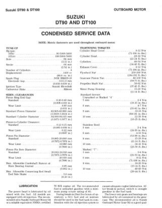
  • 1. Suzuki DT90 & DT100 OUTBOARD MOTOR SUZUKI DT90 AND DT100 CONDENSED SERVICE DATA NOTE: Metric fasteners nre used throughout outboard motor. TUNE-UP IIp/rpm: DT90 ... . .. . .... . . .. . . . ... .. . . ..... 90/5000-5600 DTlOO . . .. . . . .. . . . .... 100/5000-5600 Bore . ......... . . . . . . ............... 84 mm Stroke (:3.31 in.) . . . ....... 64 mm (2.52 in.) .. .. . . ..... ... ... .4Number of Cylinders . Displacement . .. .... 1419 cc (86.6 cu. in.) . .. ... .. . .......... NGK BRSIIS-IO .O.!H.O mm (0.035·0.0:39 in.) .Suzuki Microlink . ... .Mikuni Spark Plug Electrode Gap. Ignition Type Carburetor Make SIZES-CLEARANCES Piston Ring End Gap: Standard .... Wear Limit Standard Piston Diameter .0.20-0.40 mm (0.008-0.016 in.) ... . . ............ .0.80 mm (0.031 in.) .83.865·8:3.880 mm (3.3018-:3.:3024 in .) Standard Cylinder Diameter . ..... .. 84.000-84.015 mm (:3.:3071-3.3077 in.) Piston·to-Cylinder Clearance: Standard. . . . .. .. ... . ... 0.12-0.15 mm Wear Limit .. Piston Pin Diameter: Standard Wear Limit .. Piston Pin Bore Diameter: Standard ..... Wear Limit ... (0.005-0.006 in.) . .. 0.22 mm (0.0087 in.) . 19.9%-20.000 mm (0.7872-0.7874 in.) .. .. 19.980 mm (0.7866 in.) .. .20.002·20.010 mm (0.787,5-0.7878 in.) ..... . .. 20.030 mm (0.7886 in.) Max. Allowable Crankshaft Runout at Main Bearing .Journal ...... . Max. Allowable Connecting Rod Small End Side Shake . .... 0.05 mm (0.002 in.) . ...... .5.0 mm (0.20 in.) TIGHTENING TORQUES Cylinder Head Cover: . ... .. ...... ....... 8-12 N'm Cylinder Head ...... . ... . Cylinders ...... ... . . . . .. .. . . ..... . (iI-106 in .-Ibs.) .... 28-32 N'm (21-24 ft.-Ibs.) ... 46-54 N'm (34-40 ft.·lbs.) Exhaust Cover .. . Flywheel Nut ...... ... 8-12 N'm (71-106 in.-Ibs.) .250-260 N'm (184-192 ft.-lbs.) Gearcase Pinion Nut. . . . . . . . . .. . . . . . .. 80-100 N'm Propeller Shaft Nut (59-7:3 fUbs.) . .50-62 N'm Water Pump Housing ......... .. . . . (37-45 ft.-Ibs.) . 15-20 N'm (11-14 ft.-Ibs.) Standard Screws: Unmarked or Marked " 4" !'imm .... . ...... . ....... 2-4 N'm (18·:35 in.-Ibs.) 6 mm ..... . ...... . .. . .. .. . .. . . . . ... .4-7N·m (:35-62 in.-Ibs.) .... .... 10·16 N'm (88-141 in.-Ibs.) 8111111 ... . ... • ••. 10 mm .... . .. .... . . . .. ... .. .. . . . . .. 22-35 N'm (16-25 ft.·lbs.) Stainless Steel 5 mm .. ... . 6 nun . .. 8 mill ..... .. . . . . . . . . . . . .. . . . . .. . .2-4 N'm (18-35 in.-Ibs.) .6-10 N'm (5:3-88 in.-lbs.) ..... 15-20 N'm (11-14 fUbs.) .... :34-41 N'm (25-30 ft.-lbs.) 10 mm ........ . Marked "7": 5 mm 6 mm . 8 mill .... 10 mm .. ... . . .. ...... 3-6 N'm (26-5:3 in.-Ibs.) ..... 8-12 N'm (71-106 in.-Ibs.) ... . .. ... 18-20 N'm (13·14 fUbs.) .... .40-60 N'm (29-44 ft.-Ibs.) LUBRICATION The power head is lubricated by oil mixed with the fu el. All models are equipped with oil iljection. The recom- mended oil is Suzuki Outboard Motor Oil or a suitable equivalent NMMA certified TC-WII engine oil. The recommended fuel is unleaded gasoline with a mini- mum pump oclane rating of 85. ensure adequate engine lubrication. Af· ter break-in period, switch to straight gasoline in the fu el tank. During break-in (first five hours of op- eration), a 50; 1 fuel and oil mixture should be used in the fuel tank in com- bination with the oil iljection system to The lower unit gears and bearings are lubricated by oil contained in the gear- case. The recommended oil is Suzuki Outboard Motor Gear Oil or a good qual-
  • 2. SERVICE MANUAL ity SAE flO hypoid gear lubricalll. Gear- case capacity is ~GO mL (l8.fl fl. oz.). The gearca.-;e oil should be changed after the first to hours of operation and every toO hours thereafter. FUEL SYSTEM CARBURETOR. ~likuni BW:l6-24 car- buretors are used on Model 011)0 and Mikuni 3W40-:32 carburetor.; are used on Model DTIOO. Two carburetor.; are used on all models. l{efer to Fig. SZ18-1 for ex- ploded view. Standard main jet (12) size for normal service is 111:32.;5 on D1WJ models and #165 on DTlOO nlOdds. Standard pilotjN (6) size for normal service is 1190 on m1l0 models and !i77.5 on m'lOO models. Th check float le'e1, remo'e float bowl and invert carburetol: Distance (D-Fig. SZI8-2) between bottom of float: and float bowl mating surface on carbure· tor body should be 9.~-ll.ij mm (0.:37- 0.45 in.). Carefully bend rang on float arm to adjust. Initial selling of pilot air screw (3- Fig. SZI8-1) from a lightly seated posi- tion is I',. to I". turns. Final adjustment should be pcrfonncd with engine at nor- mal operating temperature, running in forward gear. Adjust idle speed switch (on lower engine cover) to obtain 600- 650 rpm in forward gear. Adjust pilot screw (3) so engine idles smoothly and will accelerate cleanly without hesi- tation. NOTE: II unabte to obtain 600·650 rpm in lorward gear, adjust throttle stop screw on top carburetor as necessary or check adjust· ment 01 throttle valve sensor (2). ReIer to IGNITION section. FUEL PUMP, A diaphragm type fu el pump is usee!. Fuel pump is mounted on the power head and is actuated by crankcase pulsations. I{efer to Fig. SZI8- 4 for an exploded view of pump as- sembly. Inspect diaphragms (2 and 4) for cracking, detelioration or other damage. Defective or questionable components should be renewed. Match marks are provided on cover (I) and body (:1) for correct alignment during reassembly. Tighten cover screws evenly in a cross- ing pattern. FUEL FILTER. A fuel fill er (Fig. SZI8-4) is mounted on th.. power head. Filter should be di!;&isembled to inspect element (12) every 50 hours of opera- tion. Clean clement in a suitable sol- ·enl. Renew element of excessive block- age is noted. REED VALVES. The inlet reed valves are located on a V-shaped reed plate be- tween int,lke manifold and cranke-ase. Refer to Fig. SZI8·5. The reed petals should seat very lightly against the reed plate throughout their entire length with the le,L<;t possihle tension. Renew reeds if tip of reed petal stands open more than 0.2 mm (O.OOS in .) from con- tact surface. Reed stop opening should be 10.5 mm (0.413 in.) as shown in Fig. SZIS-7. [{enew reeds if petals are broken, eracked, warped, rllsted or bent. Never attempt to bend a reed petal or straight- en a damaged reed. Never install a bent or damaged reed. Seating s1ll1-ac:e of reed plate should be smooth and flat. When installing reeds or reed stop, make sure that petals are centered over the inlet ports in reed plate, anti that reed stops are centered over reed petals. Ap- ply Suzuki Thread Lock 1:342 ora suita- ble equivalent thread locking compound to threads of reed stop screws during reassembly. Install reed vain! assemblies i.o intake manifold with alTow embossed on inside of reed plate (on one end) fac- ing toward outside of engine. SPEED CONTROL LINKAGE. '11> synchronize carburetor throttle valves. loosen two screws (S-Fjg. SZI8-8) on top earburetor throttle lever (L). Rotate lever (L) clockwise until throttle v<llves are eompletely closed, then retighten screws (S). Be sure throttle valves open and dose at exactly the same time. With remote control in the neutral position, loosen jam nuts (N-Fig. SZIS-9) and ad- just lengt.h of rod (I) so a c:icarance of Fig. SZIS-4-Exploded view of fuel pump and fuel filter as- sembly. I C,I'l'r :!. 1"}I j)phm~1Il ;j !-)dy .1. U'iiJ ,h F1.Ijl.1I1 .j SI}l'"i lllol, ,; 11)111''' pbl~' . , " 0" rinj( K . ~hl1 ~ I W".,ht'r (I F,hl'r b..",- 11. Pt1ckin" I:! FIJkr .-,I.·IIwnl I:l . " 0" rloil. If CIII' Suzuki 0190 & 01100 Fig. SZI8-1-Exploded view of carburetors used on all modelS. Hood' Thr;,n k· ';iln: S('tl.$lI f" :) Pilot ~·rt."., ·1. Inll~t '.1' 1' 1: ".':11 I~in (i . rUt" Jet I. Jo'U;'l1 k 1I 1~~1 ~I )O!.~,1 "!lui...." !I lif';."1 ill :1111 j"t 1I"ld';:r II GiJ..s)WI I i. ) l:dnJl'b I:;. fin,-u bllwl ,.1. I.in'c rod Fig. SZIS·2-Floal height (D) should be 9.5· I 1.5 mm (0.37-0.45 in.). Bend lang on float arm to ad/usl.
  • 3. Suzuki DT90 & 01100 I mm (OJH in.) is present between throt- tle lever (.~) and stopper (5) on carbure- tor. Refer 10 OIL IN.JECTION section for iqjeLtion pump control linkage ad- justment. Fig. SZI8-6-Exploded view of intake manifold and reed valve Bssemblles. 1 InUtkc rn:inlfold 2. CiiI.S).;.'-l :3 Hced pau~ 10.5mm (0.413 In.) <1 H('l'd p(-l:,lb :;. H('('d st(Jp Fig. SZI8-7-Dls/Mce belween reed slap (5) and reed plale (3) should be 10.5 mm (0.413 In.) ss shown. CleafsnC6 between reed petal (4) Bnd reed plele (3) musl not exceed 0.2 mm (0.008 In.). R--~ Fig. SZ18-8-Refer to text to synchronize carbu- retor thronle valves. To ease engine stalting, ignition lim- ing is electronically advanced to 5 de- grees BTDC. The starting ignition ad- vance duration is 15 seconds when engine temperature is below 87°-1100 C (:36°-44° F) and 5 seconds when enb'ine is warmed to 97°-110° C (3(j0-44° F) or above. After the initial timing advance period. idle speed timing is controlled by thp. idle speed adjustment switch. The idle speed acljustment switch varies timing from 7 degrees ATDC (slow) to TDC (fast), changing idle speed approx- imately 50 rpm per position. Full throttle timing should be 2:3 de- grees BTDC at 5000 rpm and is electron- ically controlled by the Micro Link pro- cessor. The processor uses information from the gear counter coil and the throt- tle valve sensor to determine the opti- mum ignition timing for all operating conditions. Hefer to IGNITION section for throttle ,·alve sensor acljustment procedure. OIL INJECTION BLEEDING PUMP. Air should be purged from irjection system any time an irljection system component has been removed or renewed, or if outboard mo- tor has been in storage. While bleeding the system, a 50:1 fuel and oil mixture must be used in the fuel tank to ensure proper engine lubrication during the bleeding procedure. Open the air bleed screw (B-Fig. SZIH-Il) two or three turns. Start engine and run at MiO-700 rpm until air is no longer noted at screw (n). Stop engine and tighten screw (il) securely. CHECKING OIL PUMP OUTPUT. Start engine and warm-up for approxi- mately five minutes. Stop engine. re- move oil reservoir and disconnect oil pump control rod (2-Fig. SZIS-Il) from carbureto!: Connect Suzuki oil measur- ing cylinder 08!J4HiH7!O to oil pump in- let hose and fill with a recommended engine oiL l3Ieed air from system as previously outlined, then refill oil cyl- inder to an upper reference mark. Ho- tate oil pump control lever to the fully closed (clockwise) position, start engine and run at 1500 rpm for exactly five 1mm ro.cw in)';~;:~? OUTBOARD MOTOR minutes. After five minutes. slop engine and note oil mea.,uring cylinder. Oil con- sumption in five minutes at 1500 rpm should be 2.5-4.5 mL (OJ)H5-0.152 fl. oz.). Next. refill oil cylinder, rotate oil pump control lever to the full-open (counterclockwise) position, start en- gine and run at 1500 rpm for exactly two minutes. Stop engine and note oil cyl- imler. Oil consumption in two minutes at 1500 rpm should be (j.O-8.0 mL (0.203- 0.:304 fl. oz.). After reconnecting oil pump control rod to carburetOl; be sure carburetor throttle valves are properly synchronized (SPEED CONTHOL LiNK- AGE) and check acljustment of oil pump control rod as outlined in PUMP CON- TROL ROD ADJUSTMENT section. NOTE: 011 pump output test results may vary depending on testing error and ambient temperature. To ensure accurate results, re- peat test three times, or until results are consistent. Renew oil pump assembly (I) if out- put is not as specified. Be sure pump is properly engaged with driven gear (:3) before tightening fasteners. OIL FLOW SENSOR. Oililow sensor (9-Fig. SZIS-II) is connected in-line be- tween oil reservoir and oil pump. The oil flow sensor serves as an oil filter as well a.g a sensor to detect insufficient oil flow to pump. Should oil flow become restricted, the sensor circuit closes, sig- naling the microcomputer to decrea.,e engine speed and activate the warning lamp and buzzer. The sensor filter should be periodical- ly removed and cleaned in a SUitable sol- vent. Henew filter if excessive blockage is noted. Tb test sensor. connect an ohmmeter between sensor pinklblue wire and black wire. No continuity should be present. Next. plug sensor inlet and ap- ply a vacuum to the outlet port. Zero ohms should be noted with vacuum applied. PUMP CONTROL ROD ADJUST- MENT. Make sure carburetor throttle Fig. SZI8-9-VIew ofthrottle linkage on all models. I Link roo 1.. ThTOftl(' ann 3. Curhuret.or 4. Throttle I(''~'r 5. S(t)PrK'r S . luu
  • 4. SERVICE MANUAL valves are properly synchronized as de- scribed in SPEED CONTROL LINKAGE section. With throttle in the fully closed position, clearance (C-Fig. SZIS-12) be- tween boss (4) and control lever (3) should be less than 1.0 nlIn (0.0:,9 in.), but lever (3) should not be touching boss (4). Loosen nuts jam nuts (N) and vary length of rod (2) to adjust. IGNITION All models are equipped with Suzuki Micro Link ignition system. 1Ilicro Link is comprised of a capacitor discharge ig- nition system (CDl) and a microcom- puter. The microcomputer processes in- formation from various sensors and switches including throttle valve open- ing, engine rpm and shift lever position, then determines the optimum ignition timing. The ]llicro Link system also mon- itors oil level, oil flow, water flow and overspeed caution systems. If one or more eaution systems indicate a mal- function, the microcomputer activates the appropriate warning buzzer and lamp, and reduees engine speed to a predetermined level. TROUBLE-SHOOTING. Test ignition system using Stevens 1I10dei CD-77 or a suitable equivalent peak reading volt- meter (PRV) and Suzuki Pocket Tester 09900-25002 or a suitable equivalent ohmmeter. Refer to Figs. SZIS-14 and SZIS-L3. 1b check ignition system peak voltage, remove spark plugs, and refer to chart in Fig. SZIS-16. Output is measured at cranking speed only. Make sure battery is fully charged and in good condition. If peak voltage is less than specified in chart, renew component being tested. If testing ignition components using Suzuki Pocket '!ester 09900-25002, or an ohmmeter, refer to Figs. SZIS-14 and SZIS-15 and proceed as follows: COlDENSER ClIARGE COIL. Discon- nect six-pin connector (Fig. SZIS-15) leading from stator plate. Connect ohm- meter between the black/red terminal and the green terminal. Resistance should be 180-270 ohms. PULSER COILS. Disconnect the six- pin connector leading from stator plate. Connect tester between engine ground and alternately to the red/green, white/black, red/white and white/green terminals. Resistance at each terminal should be 160-230 ohms. Air gap between pulser coils and the flywheel should he 0.7!; mm (0.029 in.). The manufacturer recommends using Suzuki pulser eoil IDeating tool (part 09931-88710) to properly position puls- er coils. GEAR COUNTER COIL. Unplug con- nectors leading from gear counter coil (8-Fig. SZIS-15). Connect tester be- tween the orange/green and the black!green wire eonneetors. Resistance should be 160-230 ohms. Air gap between counter coil and the flywheel ring gear teeth should be 0.5 mm (0.020 in.). Loosen counter coil mounting screws and slide coils as necessary to adjust. Fig. SZI8-11-Exploded vIew of all Injection pump and re- lated components. pnnp ~~'. (';om rol rod :1. DIi'('n "War -1. G~k('l R~'UlITl~ r "0" ring A ir/nil niixlnp; "~Il',' H Ch('(:k '1.Llv(' o. ()j[ fI()w s(:nsqr L'I lllt'l'd Ii(;n' ..... Fig. SZI8·12-Refer to text for all pump control rod ad- Justment procedure. Pump i;L'!iy C.onlrol rod :3 G<Jn l TI1 1 it.''(,'r 1. &$:.1 ~ ,J(,m nuts Suzuki OT90 & OT100 BATTERY CHARGE COILS. Unplug the yellow and red wire connectors and connect tester between the two connec- tors. Resistance should be 0.4-0.6 ohm. Note that checking resistance between the yellow and red wires tests resistance of both battery charge coils. IGNITION COILS. Ignition coil primary winding resistance should be 0.15-0.25 ohm. Connect tester between black and carburetor •
  • 5. Hello Thank you very much for your patience. At the bottom of the page there is a FREE ADD TO CART button. Click on it and you will get zip file on the bottom Please click here. Go back to the page. of the page.