
Recommended
Recommended
More Related Content
What's hot
What's hot (19)
Similar to Htr india-products-surface-mount-resistor-rls-english.pdf
Similar to Htr india-products-surface-mount-resistor-rls-english.pdf (20)
Recently uploaded
Recently uploaded (20)
Htr india-products-surface-mount-resistor-rls-english.pdf
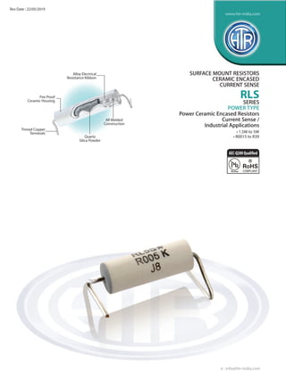
- 1. Alloy Electrical Resistance Ribbon Tinned Copper Terminals Quartz Silica Powder Fire Proof Ceramic Housing All Welded Construction SURFACE MOUNT RESISTORS CERAMIC ENCASED CURRENT SENSE RLS SERIES POWER TYPE Power Ceramic Encased Resistors Current Sense / Industrial Applications • 1.5W to 5W • R0015 to R39 e : info@htr-india.com www.htr-india.com Rev Date : 22/05/2019 AEC-Q200Qualified
- 2. RL 1.5S 1.5W 11.0 17.0 3.5 0.8 5.0 6.5 R004 R10 0.6 RL 3S 3W 15.0 20.0 5.5 0.8 8.0 8.0 R003 R22 1.2 RL 5S 5W 23.0 27.0 8.5 1.0 13.0 11.0 R0015 R39 3.5 POWER RATING at 40°C B (±1.0) DIMENSIONS (mm) RESISTANCE RANGE TYPICAL WEIGHT PER PC (gms)minA (MAX) HTR TYPE IMPORTANT MOUNTING / ASSEMBLY DATA For the guidance of the Design Engineer, our applications laboratory has given the recommended pad size and geometry which is shown below D (±0.5)C (±1.0) E (±0.5) Z (±1.0) max Resistance value checking to be done using 4½ digit micro ohm meter and insulated clips. The designer of the pad layout might prefer to split the pad for four wire checking. The temperature rise of these SMD resistors is dependent on the solder pad dimensions used and must be taken into account by the design engineer. HTR TYPE DIMENSIONS (mm) a b l RL 1.5S 2.5 (min) 5.5 13.0 RL 3S 2.5 (min) 9.5 16.0 RL 5S 2.5 (min) 16.0 23.5 SURFACE MOUNT CERAMIC ENCASED CURRENT SENSE RLS PHYSICAL CONFIGURATION e : info@htr-india.com www.htr-india.com Rev Date : 22/05/2019
- 3. ELECTRICAL AND ENVIRONMENTAL CHARACTERISTICS / DATA Power Rating Full power dissipation at 40°C and linearly derated (Rated Ambient Temperature) to zero at 275°C (Refer derating curve above) Resistance Tolerances Available ±10% [K]; ±5% [J]; ±3% [H]; ±2%[G]; ±1% [F] Operating Temperature Range -55°C to +275°C (with suitable derating as per derating curve) Voltage Proof / Limiting Voltage / Max. Working Voltage V = PxR Voltage Proof / Dielectric Withstanding Voltage DR ± (0.2% + R0005) No flashover or (Based on 1000V rms for 60 secs) mechanical damage Insulation Resistance [MIL STD 202F - Test method 302] > 1000M (Min) Short Time Overload DR ± [0.5% + R0005] - Average (5 x Rated power upto 2 watts and 10 x DR ± [1% + R0005] - for resistance values Rated Power 3 watts and above for 5 secs) near maximum range Temperature Co-efficient of Resistance ± 60 to 400 ppm/°C (Depending on resistance value) (Measured from-55°C to +125°C referenced to +25°C) Thermal Shock DR ± [0.2% + R0005] - Average [-65°C to +125°C, 5 cycles, 15 min at each extreme temperature] Moisture Resistance DR ± [0.2% + R0005] [MIL STD 202F Test method 106E with step 7b eliminated] Damp Heat (Steady State) / Humidity DR ± [0.5% + R0005] (70°C at 95% R.H for 250 hours) Endurance - Load Life DR ± [1.5% + R0005] Average - 2000 hour duration [70°C with limiting voltage - 1.5 hours on / 0.5 hours off] DR ± [0.5% + R0005] Typical - 1000 hour duration Solvent Resistance [IPA for 60 secs ± 10 secs] No effect on case filling / marking PARAMETER/PERFORMANCE TEST & TEST METHOD PERFORMANCE REQUIREMENTS SURFACE MOUNT CERAMIC ENCASED CURRENT SENSE RLS TYPICAL APPLICATIONS The introduction of these low ohm / current sense resistors with surface mounting has broadened the scope for designers substantially as they fulfill a long standing demand for surface mount high power resistors for current sense purposes. Note :The ceramic cases used may be steatite ceramic, corderite ceramic or high alumina ceramic.Thus, the ceramic cases may beoff-white or variations of brown / grey, colours which are inherent to these ceramic material. Resistance to Soldering Heat (260°C - 270°C for 4 secs) ∆R ± [0.1% + R0005] - Typical Solderability (MIL STD 202F Test Method 208F) Must meet the requirements laid down (95% satisfactory coverage) Marking As per IEC Pub. 60062 MECHANICAL SPECIFICATIONS For RoHS version - RL3S * PARAMETER/PERFORMANCE TEST &TESTMETHOD PERFORMANCE REQUIREMENTS ORDERING INFORMATION Series HTR Type Packing Resistance Value Tolerance RLS RL3S / RL3S* Bulk RL3S / RL3S* R047 J e : info@htr-india.com www.htr-india.com Rev Date : 22/05/2019