SPACE SAVER
Slim Type Vertical Mounting
Alloy Resistance
Ribbon
• Especially designed for crowded PCB’s
• Ceramic stand-offs.
• Any resistance value possible within
resistance range given
Strategies for Unlocking Knowledge Management in Microsoft 365 in the Copilot...
HMVL - CURRENT SENSE / LOW OHM CERAMIC ENCASED TYPE (OLD)
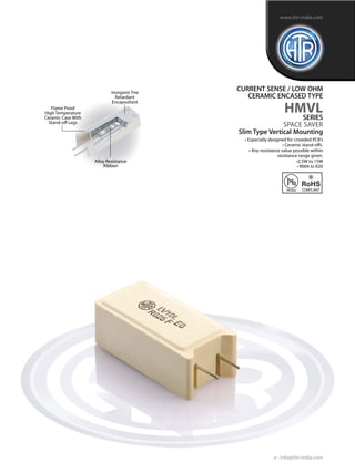
1. Inorganic Fire
Retardant
Encapsultant
Alloy Resistance
Ribbon
Flame Proof
High Temperature
Ceramic Case With
Stand-off Legs
CURRENT SENSE / LOW OHM
CERAMIC ENCASED TYPE
HMVL
SERIES
SPACE SAVER
Slim Type Vertical Mounting
• Especially designed for crowded PCB’s
• Ceramic stand-offs.
• Any resistance value possible within
resistance range given.
•2.5W to 15W
• R004 to R20
e : info@htr-india.com
www.htr-india.com
Rev Date : 03/02/2016
2. PHYSICAL CONFIGURATION
M2L 2.5W 11.0 20.5 7.0 0.8 5.0 R004 R063 3.5
M4L 4W 12.0 25.0 7.0 0.8 5.0 R004 R10 4.5
LV5L 5W 13.0 25.5 9.0 0.8/1.0 5.0 R004 R10 6.0
M7L 7W 12.5 38.0 9.0 0.8/1.0 5.0 R005 R15 7.0
LV7L 7W 13±1.5 38.5 9.0 0.8/1.0 5.0 R005 R15 12.5
LV10L 10W 16.0 35.0 12.0 0.8/1.0 7.5 R005 R15 14.5
LV10AL 10W 13.0 50.0 9.0 0.8/1.0 5.0 R005 R20 12.5
LV15L 15W 20±1.5 38 13.0 1.0 7.5 R005 R15 30
POWER
RATING
at 70°C
DIMENSIONS (mm) RESISTANCE
RANGE
TYPICAL
WEIGHT
PER PC
(gms)
min
W
±1
HTR
TYPE
max
• LV5L / M7L / LV7L / LV10L / LV15L and LV10AL are also available with 1mmØ
terminations which contributes to lowering the TCR of the resistor.
• The resistance values must be checked using 4½ digit micro-ohm meter with
four wire system and insulated clips.
H
±1.5
D
±1
φ d
±0.05
P
±1
CURRENT SENSE /
LOW OHM
CERAMIC
ENCASED TYPE
HMVL
ELECTRICAL AND ENVIRONMENTAL
CHARACTERISTICS / DATA
PARAMETER/PERFORMANCE TEST & TEST METHOD PERFORMANCE REQUIREMENTS
Power Rating (Rated Ambient Temperature) Full Power dissipation at 70°C and linearly derated to zero
at +275°C (Refer Derating Curve above)
Resistance Tolerances Available ±10% (K); ±5% (J); ±3%(H); ±2%(G); ±1%(F); ±0.5%(D)
Operating Temperature Range -55°C to +275°C with suitable derating as per derating curve.
Voltage Rating / Limiting Voltage / Max. Working Voltage V= PxR
Voltage Proof / Dielectric Withstanding Voltage ∆R ± [1% + R05] - Average.
(based on 1000V rms for 60secs) No flashover or mechanical damage
Insulation Resistance [MIL STD 202F - Test Method 302] >1000M (Min)
Short Time Overload ∆R ± [1% + R0005] - Average
(5 x Rated power upto 2 watts and 10 x Rated power ∆R ± [2% + R0005] -
3 watts and above for 5 secs) For resistance values near maximum range.
Temperature Co-efficient of Resistance ±60 to 400 ppm/°C (Depending on resistance value)
[Measured from -55°C to +125°C referenced to +25°C]
Thermal Shock [-65°C to +125°C, 5 cycles, ∆R ± [1.5% + R0005] - Average
15 mins at each extreme temperature]
Mechanical Shock (Specified Pulse) ∆R ± [0.75% + R0005] - Typical
[MIL STD 202F - Test Method 213B condition 'C']
Moisture Resistance [MIL STD 202F - Test Method ∆R ± [1.25% + R0005] - Average
106E with step 7b eliminated]
Damp Heat (Steady State) / Humidity (40°C at 95% R.H for 250 hours) ∆R ± [1.5% + R0005] - Typical
Endurance - Load Life ∆R ± [2.5% + R0005 ] - Average - 2000 hours duration
(70°C with limiting voltage - 1.5 hours on / 0.5 hours off) ∆R ± [≤ 2.0% + R0005 ] - Typical - 1000 hours duration
Solvent Resistance [IPA for 60 secs ±10 secs] No effect on case filling / marking
e : info@htr-india.com
www.htr-india.com
Rev Date : 03/02/2016
3. TYPICAL APPLICATIONS
These resistors find wide application in inverters and power supplies.
The HMVL series offers a practical solution to current sensing applications where PCB space is at a premium and low inductance is required
- SMPS and linear power supplies.
For the effective utilization of these resistors, please refer“Application / Design notes for current sense resistors”.
Note :The ceramic cases used may be steatite ceramic, corderite ceramic or high alumina ceramic.Thus, the ceramic cases may beoff-white
or variations of brown / grey, colours which are inherent to these ceramic material.
Pull Test / Robustness of Terminations No effect
[Direct load 2 to 4.5 Kgs depending on size for 15 secs]
Resistance to Soldering Heat ∆R ± [0.1% + R0005] - Typical
(260°C - 270°C for 4 secs)
Solderability Must meet the requirements laid down
[MIL STD 202F - Test Method 208F] (95% satisfactory coverage)
Marking As per IEC Pub. 60062
MECHANICAL SPECIFICATIONS
1. For RoHS version - M-7L *
2. For 1mm terminations - M-7L (1)
ORDERING INFORMATION
Series Type Packing Resistance Value Tolerance
HMVL M7L/M7L* Bulk M7L/M7L* R068 J
PARAMETER/PERFORMANCE TEST & TEST METHOD PERFORMANCE REQUIREMENTS
•Temperature rise at solder joint on PCB would be substantially
lower. (Consult factory for details)
TEMPERATURE RISE (AT FULL POWER)
(Ambient temperature 32°C)
CURRENT
SENSE / LOW
OHM
CERAMIC
ENCASED TYPE
HMVL
e : info@htr-india.com
www.htr-india.com
Rev Date : 03/02/2016
![PHYSICAL CONFIGURATION
M2L 2.5W 11.0 20.5 7.0 0.8 5.0 R004 R063 3.5
M4L 4W 12.0 25.0 7.0 0.8 5.0 R004 R10 4.5
LV5L 5W 13.0 25.5 9.0 0.8/1.0 5.0 R004 R10 6.0
M7L 7W 12.5 38.0 9.0 0.8/1.0 5.0 R005 R15 7.0
LV7L 7W 13±1.5 38.5 9.0 0.8/1.0 5.0 R005 R15 12.5
LV10L 10W 16.0 35.0 12.0 0.8/1.0 7.5 R005 R15 14.5
LV10AL 10W 13.0 50.0 9.0 0.8/1.0 5.0 R005 R20 12.5
LV15L 15W 20±1.5 38 13.0 1.0 7.5 R005 R15 30
POWER
RATING
at 70°C
DIMENSIONS (mm) RESISTANCE
RANGE
TYPICAL
WEIGHT
PER PC
(gms)
min
W
±1
HTR
TYPE
max
• LV5L / M7L / LV7L / LV10L / LV15L and LV10AL are also available with 1mmØ
terminations which contributes to lowering the TCR of the resistor.
• The resistance values must be checked using 4½ digit micro-ohm meter with
four wire system and insulated clips.
H
±1.5
D
±1
φ d
±0.05
P
±1
CURRENT SENSE /
LOW OHM
CERAMIC
ENCASED TYPE
HMVL
ELECTRICAL AND ENVIRONMENTAL
CHARACTERISTICS / DATA
PARAMETER/PERFORMANCE TEST & TEST METHOD PERFORMANCE REQUIREMENTS
Power Rating (Rated Ambient Temperature) Full Power dissipation at 70°C and linearly derated to zero
at +275°C (Refer Derating Curve above)
Resistance Tolerances Available ±10% (K); ±5% (J); ±3%(H); ±2%(G); ±1%(F); ±0.5%(D)
Operating Temperature Range -55°C to +275°C with suitable derating as per derating curve.
Voltage Rating / Limiting Voltage / Max. Working Voltage V= PxR
Voltage Proof / Dielectric Withstanding Voltage ∆R ± [1% + R05] - Average.
(based on 1000V rms for 60secs) No flashover or mechanical damage
Insulation Resistance [MIL STD 202F - Test Method 302] >1000M (Min)
Short Time Overload ∆R ± [1% + R0005] - Average
(5 x Rated power upto 2 watts and 10 x Rated power ∆R ± [2% + R0005] -
3 watts and above for 5 secs) For resistance values near maximum range.
Temperature Co-efficient of Resistance ±60 to 400 ppm/°C (Depending on resistance value)
[Measured from -55°C to +125°C referenced to +25°C]
Thermal Shock [-65°C to +125°C, 5 cycles, ∆R ± [1.5% + R0005] - Average
15 mins at each extreme temperature]
Mechanical Shock (Specified Pulse) ∆R ± [0.75% + R0005] - Typical
[MIL STD 202F - Test Method 213B condition 'C']
Moisture Resistance [MIL STD 202F - Test Method ∆R ± [1.25% + R0005] - Average
106E with step 7b eliminated]
Damp Heat (Steady State) / Humidity (40°C at 95% R.H for 250 hours) ∆R ± [1.5% + R0005] - Typical
Endurance - Load Life ∆R ± [2.5% + R0005 ] - Average - 2000 hours duration
(70°C with limiting voltage - 1.5 hours on / 0.5 hours off) ∆R ± [≤ 2.0% + R0005 ] - Typical - 1000 hours duration
Solvent Resistance [IPA for 60 secs ±10 secs] No effect on case filling / marking
e : info@htr-india.com
www.htr-india.com
Rev Date : 03/02/2016](data:image/gif;base64,R0lGODlhAQABAIAAAAAAAP///yH5BAEAAAAALAAAAAABAAEAAAIBRAA7)