Apidays New York 2024 - Passkeys: Developing APIs to enable passwordless auth...
Spe71510 Final
1. SPE 71510
Segregated Flow is the Governing Mechanism of Disproportionate Permeability
Reduction in Water and Gas Shutoff
A. Stavland, SPE, RF-Rogaland Research and S. Nilsson, RF-Rogaland Research
Copyright 2001, Society of Petroleum Engineers Inc.
buildup in the treated zone.1 The producing WOR is in such
This paper was prepared for presentation at the 2001 SPE Annual Technical Conference and situations the same as before the treatment.
Exhibition held in New Orleans, Louisiana, 30 September –3 October 2001.
However, the same general understanding of the governing
This paper was selected for presentation by an SPE Program Committee following review of
information contained in an abstract submitted by the author(s). Contents of the paper, as
mechanism for DPR has not yet been reached. The literature
presented, have not been reviewed by the Society of Petroleum Engineers and are subject to has suggested different mechanisms. The most frequent
correction by the author(s). The material, as present ed, does not necessarily reflect any
position of the Society of Petroleum Engineers, its officers, or members. Papers presented at proposed methods are:
SPE meetings are subject to publication review by Editorial Committees of the Society of
Petroleum Engineers. Electronic repr oduction, distribution, or storage of any part of this paper
- Polymer adsorption at the pore surface and the possibility
for commercial purposes without the written consent of the Society of Petroleum Engineers is to alter the wettability to more water-wet situation as well
prohibited. Permission to reproduce in print is restricted to an abstract of not more than 300
words; illustrations may not be copied. The abstract must contain conspicuous as some lubrication effects
acknowledgment of where and by whom the paper was presented. Write Librarian, SPE, P.O.
Box 833836, Richardson, TX 75083-3836, U.S.A., fax 01-972-952-9435.
- Selective shrinking (or dehydration) and swelling of
polymer and crosslinked gel
- Segregated flow of oil and water
Abstract - Balance between the opposing capillary forces and elastic
This paper describes the mechanism for disproportionate confining forces
permeability reduction (DPR). Recent papers have discussed Finally, there are suggestions that there could be combinations
possible DPR mechanisms. Most of the papers conclude that of these mechanisms. One reason for the lack of consensus
there is not yet a single factor that determines DPR. The about DPR mechanisms may be that DPR is observed for both
intention of this paper is to clarify that there is a single model, single polymers and crosslinked gel. It has been argued that
which explains the observed DPR effects. This model relies on DPR depends on the reservoir characteristics (e.g. lithology,
segregated flow of oil and water at pore level and on pore size distribution and wettability).
continuity in the oil phase at placement of the DPR fluid. With This paper intends to demonstrate that it is possible to
this model DPR is demonstrated for both gel and single easily explain that the governing mechanism for all types of
polymer systems at different wettabilities. Oil continuity is DPR fluid is caused by segregated flow. In this context
normally easier to obtain for single polymers than for segregated pathways, can either result from preferred flow of
crosslinked gels. Gel systems may, however, be more robust. one phase in a certain set of channels or result from preferred
The paper describes a method for placement of water-soluble flow of one phase in defined parts of the channel.
gel while maintaining open pathways for oil. Additionally, it is It may be convenient to recapitulate basic knowledge about
shown that using the phase permeability reduction ratio is not location of wetting and nonwetting phases in a porous
a good measure for defining optimum DPR. Therefore a new medium. The permeability reduction is affected by wettability
selectivity parameter is introduced which demonstrates to be and endpoint permeabilities. According to Anderson2 the
more effective. wetting fluid will preferentially occupy the smallest pores and
be in contact with the majority of the rock surface. The
Introduction nonwetting fluid will occupy the centers of the larger pores
It is commonly accepted that DPR reduces water permeability and form globules that extend over several pores. Lake 3
more than oil (or gas) permeability and therefore, may be a reported that at endpoint saturation the nonwetting phase
method for water shutoff. A number of publications have occurs in isolated globules and occupies the center of the
discussed DPR. It seems to be a general understanding that pores. The trapped wetting phase occupies the crevices
DPR is most effective when used against water production between rock grains and coats the rock surface. The wetting
caused by coning or in situations where the watered out layers phase endpoint permeability will therefore be smaller than the
are separated from the oil producing layers. In situations with nonwetting phase endpoint. Some examples are given below:
2-phase flow a DPR treatment (even an idealized) will cause In a wetted system the flow of the wetting phase is
an increased pressure drawdown because of water saturation dominant close to the wetting surface. The nonwetting phase
flows in the middle of the channel. In a water-wet system,
2. 2 A. STAVLAND AND S. NILSSON SPE 71510
flow of water is preferred at the surface, leaving the oil to flow water saturation is increased. However, a DPR effect is
in the middle of the larger pore and vice versa for oil-wet obtained. Table 1 shows the calculated endpoint permeabilities
systems. and permeability reduction ratios (RRFw /RRFo ). Ratios larger
Another example is flow of the wetting phase through a than unity demonstrate DPR. By this exercise the following
pore with a pressure drop given by the Poiseuille law. For the can be found:
nonwetting phase to flow through the same pore filled with the - Corey exponent αw > αo , the shift in saturation will reduce
wetting phase a certain entrance pressure caused by capillary the endpoint permeability for water more than for oil
effects is needed. If the entrance pressure is not exceeded there (RRFw /RRFo > 1, i.e. DPR)
will be no flow of the nonwetting phase. - Corey exponent αw < αo , the shift in saturation will reduce
A DPR fluid is here a fluid with the ability to reduce the the endpoint permeability for oil more than for water
water permeability more than the hydrocarbon permeability. (RRFw /RRFo < 1)
For simplicity we discuss only oil permeability but the same - Corey exponent αw = αo , the relative permeability curves
arguments hold also for gas permeability. The most common are symmetric and the permeability reduction for oil and
DPR fluids are chemicals with the ability to form a gel in the water will be the same (RRFw /RRFo = 1)
pore space or chemicals retained in the pore space. Both As a first approximation one may use the saturation shift and
mechanisms reduce the effective porevolume. As will be the asymmetry of the relative permeability curves to
shown, because of the segregated pathways the pore restriction demonstrate a DPR effect. The same results can be obtained
is dominant for the phase in which the DPR fluid is soluble. In assuming the shift in the residual oil saturation to Sor ’ = Sor +
the following, different possibilities of obtaining DPR are ∆S or .
demonstrated. Then, assume that the fluid injected alter the wettability
(i.e. alter the Corey exponents from αo1 > αw1 before injection
Saturation shift and wettability to αo2 < αw2 after injection). Then the water permeability is
Acock and Reis 4 discussed how to reduce the permeability by reduced more than the oil permeability, as shown in Fig. 2.
lowering the porosity by salt precipitation (a potentially DPR Here the initial Corey exponents are 4 for oil and 2 for water.
fluid). Without yet going into the details of the DPR After treatment they are 2 and 4, respectively. Since we only
mechanisms, is it possible to describe a DPR effect only by calculate the permeability reduction ratio at endpoint, this
altering the porosity (i.e. irreducible saturation)? Assume
situation is the same as the case in Table 1 with αw = 4, and αo
standard relative permeability curves (eq.1) and injection of a
= 2 and ∆S w =0.2. If the Corey exponents could be a measure
fluid capable of reducing the available pore volume (porosity)
for wettability, alteration of the wettability to a more water-
for water by whatever mechanism (e.g. adsorption, retention,
wet situation and a shift in water saturation may cause DPR.
precipitation, filtration or gel formation).
So far we have shown that the endpoint relative
k rw (S w ) = k rw ( S w ) αw
0 ∗
(1) permeability reduction may give rise to a DPR effect, however
k ro ( S w ) = k ro (1 − S w ) αo
0 ∗
(2) small. This has been shown by only exploiting the slope of the
relative permeability curves (wettability) and endpoint
where, 0
kri is the endpoint relative permeability, αi is the saturation’s. As will be shown later DPR becomes more
Corey exponent. The Corey exponent can be a measure for the pronounced if the pore size restriction is included.
wettability. The wetting phase Corey exponent is normally
higher than the nonwetting phase Corey exp onent. S * is the Pore size restriction
w
It is well known that both polymer and polymer gel have the
normalized water saturation defined as: ability to block the pores or restrict the pore size. There are at
Sw = ( Sw − S wi ) /(1 − Sor − Swi )
*
(3) least two mechanisms for this pore size restriction.
The reduction in porosity is expressed by an increase in the Polymer retention (which includes the terms adsorption,
irreducible water saturation, S wi ’ = S wi + ∆S wi , Where ∆S wi is mechanical entrapment, precipitation, etc). Typical for these
the shift in irreducible water saturation (i.e. the reacted DPR retention mechanisms is that the permeability reduction
fluid act as immobile water). increases with decreased initial permeability and with
Because of the shift in saturation the relative permeability decreased pressure gradient. In this notation, adsorption is
curves will be altered and may give rise to a DPR effect. As only one of several retention mechanisms.
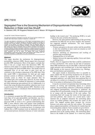
shown in Fig. 1, the endpoint water relative permeability i s Gel formation. Gel is formed by crosslinking of polymers
shifted downwards from k rw = 0.5 before treatment to k rw = into a 3D network. It is assumed that the gel behaves the same
0 0
way in the porous media as in a bulk phase. As a first
0.13 after treatment (RRFw = 2.60). Here k ro = 1, k rw = 0.5, S wi approximation we can assume that gel restricts flow
= 0.1, S or = ∆S wi = 0.2. The Corey exponents were 4 for water considerably. As with polymer retention the permeability
and 2 for oil. As long as the residual oil saturation is not reduction increases as the pressure gradient decreases, but for
changed, the endpoint water relative permeability is reduced. most gel systems the permeability reduction increases with
The endpoint oil relative permeability is reduced as well from increasing permeability.5, 6
1.0 to 0.51 (RRFo = 1.96), simply because the irreducible
3. SPE 71510 SEGREGATED FLOW IS THE GOVERNING MECHANISM OF DPR IN WATER AND GAS SHUTOFF 3
A simple and frequently used model for a porous media is following observation should be observed during the coreflood
a bundle of capillary tubes. In this model an adsorbed layer at experiments: A pressure increase during the polymer injection
the surface of the water-wet tubes will reduce the pore space until the adsorbed layer is established. The differential
and reduce the permeability to water more than to oil. pressure should then level off corresponding to the mobility
Segregated pathways can interpret this effect. Water flows reduction (permeability reduction multiplied by the relative
close to the water-wet surface and will be restricted. The oil polymer viscosity). At the same time the produced polymer
flows unrestricted in the middle of the pores as long as the concentration should be equal to the injected concentration.
thickness of the adsorbed layer is not too large. This flow The normal observation for DPR polymers is, however, a
behavior has been demonstrated theoretically both with regular gradual increase in differential pressure (increases as the
pores7-8 and with more realistic pore size distribution.9-11 injected volume increases) without the differential pressure
Experimental data have also been used to support the adsorbed leveling off. The produced polymer concentration is lower
layer as the DPR mechanism. 12-13 Notice that this model also than the injected. This indicates a filtration process rather than
includes the volume restriction (shift in S wi ) in addition to pore general adsorption. A study in micromodels 16 using water-wet
size restriction. porous media supports this. The retained polymer was reported
Refs. 7 and 8 determined the permeability reduction, RRF, as polymer entanglement (which is essentially an adhering of
from an adsorbed polymer layer with thickness, e, using polymer, forming a network on the pore surface that is
capillary tube bundles and Poiseuille flow. They obtained the constantly replenished from the flowing polymer solution) on
following equation: the crevices between the grains.
e This retention mechanism is probably less influenced by
RRF = (1 − ) − 4 (4) wettability than adsorption, and may explain why permeability
r
where, r, is the pore radius. An extension of this model, which reduction is observed even in true oil-wet Teflon cores during
may be used to demonstrate the effect of a shift in S wi after polymer injection.17-18 However, ref. 16 reports no
treatment, is given by the following equation: permeability reduction in oil-wet micromodels, which may be
e because of the pore structure used.
∆ Swi = 1 − (1 − ) 2 (5) Mechanical polymer retention can still explain why the
r permeability reduction increases as the permeability decreases.
By using eq. 4 and saying that ∆S wi is the same as the relative The fraction of small pore channels able to be blocked by
change in porosity, ∆φ/φ, one get: polymer aggregates increases as the permeability decreases.
1 ∆φ 2 In this model filtration of polymer, polymer aggregates and gel
= (1− ) (6)
RRF φ aggregates will act similarly but with stronger permeability
as shown by Acock and Reis.4 However, they claimed that the reduction for aggregates than for single polymer. As long as
following expression gave a better fit to the experimental data: the aggregates follow the water-preferred pathways, they will
reduce the water permeability more than the oil permeability.
RRF = e 5∆φ / φ (7) If optimized, retention will take place only in the smallest
The adsorbed layer model will, however, not work for oil-wet pore channels, which represent only a small fraction of the
media.8 Therefore the adsorbed layer model is not a general pore volume, but will contribute strongly to the permeability
model for the DPR mechanism. With adsorption on an oil-wet for the wetting phase. Thereby it may be possible to minimize
surface, the model should predict higher permeability the shift in water saturation and maintain high endpoint oil
reduction for oil permeability than for water, simply because permeability.
oil is the wetting phase and will flow close to the surface and Fig. 3 shows the change in permeability reduction as a
be restricted by the adsorbed layer. Nevertheless experiments, function of permeability. The same polymer system has been
showing a DPR effect in what is claimed to be an oil-wet injected into porous media with different permeabilities. As
media using an adsorbing polymer have been interpreted with can be seen the permeability reduction increases with
the adsorbed layer model.12-14 However, it is unlikely that a decreased water permeability. A power law relation seems to
water-soluble polymer will adsorb at an oil-wet surface. It may give a better fit than that expressed in eq. 4 (assuming constant
be that the claimed oil-wettability is more of a mixed or thickness of the adsorbed layer and pore radius proportional to
fractional wettability where there still are some water-wet the square root of water permeability). The permeability
pathways, or that the claimed adsorption is not the governing reduction versus permeability introduces another issue. The
retention mechanism. target zone for reducing the water productivity is mainly the
Experiments three decades ago15 with different types of high permeability zone. With polymer retention there is a
polymers indicated that the permeability reduction depends on critical permeability, above which insufficient permeability
mechanical retention or filtration. It is well known that pre- reduction is obtained. This could however, be solved by
filtration improves the injectivity of a polymer through a increasing the molecular size (e.g. molecular weight) to match
porous medium. Well-filtered polymer solutions show less the pore size. But then the risk of mechanical polymer
permeability reduction than less filtered solutions. The breakdown increases because of high shear. Another issue is
adsorption level is, however, about the same. If polymer that the promising permeability reduction obtained in
adsorption should be the governing retention mechanism, the
4. 4 A. STAVLAND AND S. NILSSON SPE 71510
laboratory studies is reported not to scale directly to reservoir However, in an ideal reservoir situation (single phase water
conditions.19 production from the watered out layer and single-phase oil
When using a gel at S w = 1 the permeability reduction will production from the oil producing layer) it may be an
increase with increasing permeability5-6 At the extreme, very advantage if oil breaks the gel. Open pathways is created in
strong gels at S w = 1 reduces the permeability to a fixed level the oil zone, while water is hold back from the watered out
of some microdarcies, which can be explained as the layer. This concept may be effective until water breaks
permeability of the gel. through in the oil layer, but is not a real DPR situation. It is
Thereby a gel system will cause a permeability reduction rather a selective gel placement concept, which competes with
even in the (high permeability) watered out zone. When a gel placement concepts where gelation in the oil zone is avoided.
is used at residual oil saturation, the permeability reduction to Such concepts are beyond the scope of this paper.
water is normally a decade or more lower than at S w = 1. The Ref. 23 suggests that a balance between the opposing
effect of oil saturation will be discussed later. Even relatively forces, capillary force and elastic confining force, might
strong gels show a DPR effect, but the oil permeability contribute to DPR. The capillary force should act to maintain a
reduction, will for practical purposes be too high. The question minimum droplet radius, which in turn opens a channel
is how to minimize the oil permeability reduction. through the gel. The gel exerts an elastic confining force to
close the channel. The final radius of the oil droplet and the
Flow of oil and water through a geltreated media size of the oil pathways depend on the balance between the
Going back to our definition of segregated pathways, how can two forces. The effective permeability to oil increases with
oil be produced through a porous media where the water phase increasing radius of the flow path around the droplet. The
is gelled? For a rigid gel placed at residual oil saturation, no experimental data from corefloods in ref. 23, however, do not
oil continuous pathways should exist. Therefore no oil should support such a mechanism.
be able to flow through such a gel. For less rigid gels, It is our opinion that a balance between the capillary forces
experiments have shown the possibility of forcing oil through. and the gel elasticity is not a major DPR effect. However, if
It has been argued that an aqueous gel may swell in water there is an effect one may speculate in which direction it will
and shrink in oil.20, 21 However, this is chemically not possible. work. Consider an oil droplet at the entrance of a narrow
For an aqueous gel to shrink, water has to be extracted. There channel through the gel. If the oil droplet is a rigid particle (i.e.
is to our knowledge no known mechanism by which oil can high interfacial tension) it will tend to plug rather than to be
extract water from an aqueous gel nor has any been suggested. transported through the gel. On the other hand, if the oil
Nevertheless, this mechanism has been used to explain why oil droplet is more easily deformed (i.e. low interfacial tension)
is more easily flooded through a gelled media than water. If the droplet may be transported through the channel. This
this mechanism is operative water has to flow through the gel consideration corresponds to higher oil permeability reduction
by diffusion, which gives a strong permeability reduction. for high interfacial tension, which is the opposite of the effect
Because of gel shrinkage in oil, mobile water is separated. Oil suggested in ref. 22.
may displace this water, and bypassing the gel giving a less Nevertheless, it is well known that gel shrinkage may
permeability reduction. occur, but not selective for only one of the phases. Ref. 25
It has also been suggested that the flow of water is through demonstrated the impact on permeability reduction when using
the gel matrix, whereas the oil pushes its way through the gel a shrinking gel inside the pore network. Before shrinking took
in form of immiscible drops or filaments 22 with the flow place, both phases were blocked to flow. After some
characteristic controlled by the elasticity of the polymer gel. shrinkage, open pathways for oil (and water) were established
The oil flow will then open a channel through the gel matrix, giving a DPR effect. In addition, the water permeability
resulting in a higher permeability. Ref 22 indicates that the reduction was the same for the subsequent water cycles.
paths open by oil droplets closes after the oil has passed It is also accepted that polymer will shrink or swell
through, but without any experimentally verification. because of electrostatic shielding, e.g. by variation of brine
In corefloods where oil and water are cycled after salinity. Ref. 26 reports on a method injecting a coiled
placement of a strong gel, highest RRFw is measured in the polymer in saline brine. The polymer will then shrink giving
first water cycle. In subsequent water cycles after an oil cycle low injecting viscosity and the polymer retention causes
essential lower RRFw is measured. This indicates that the open relatively low permeability reduction. If backproduced with a
channels generated by the oil permanently destroyed some of less saline water, the retained polymer will swell giving an
the gel matrix. The gel is not repaired after the oil has forced essential higher permeability reduction.
its way through. Results23, 24 support the theory of permanent
breakdown of gel after oil is forced through it. The Segregated flow
interpretation is ref. 24 is however, by a mechanism of gel Segregated flow has been suggested as a method for DPR by
dehydration. If oil is in place before treatment, especially if the several authors.27-29 In an attempt to describe a general model
oil is mobile, the oil will have easier pathways than through for DPR, ref. 25 discussed how DPR could be interpreted by a
the gel and will, therefore, not necessarily need to break the mechanism of segregated pathways for oil and water.
gel (more about this later). Segregated pathways can in this context, either be flow of one
phase in a preferred set of channels or flow of one phase in
5. SPE 71510 SEGREGATED FLOW IS THE GOVERNING MECHANISM OF DPR IN WATER AND GAS SHUTOFF 5
defined parts of the channel. In the recent literature 30-31 this restriction of oil flow. However, since most of the flow is
mechanism is incorrectly described as Nilsson’s gel droplet through the largest pores the oil permeability reduction should
theory. be limited. The permeability reduction for both water and oil
The location of a water-based DPR fluid at different should be limited in such a pore configuration, and it is not
wettabilities and saturations are schematically shown in the obvious that a general DPR effect is observed.
dual pore model in Fig. 4, where the smallest pore only take
the wetting phase. Notice the analogue to an oil-based gel by Adsorption
changing oil with water and shifting the wettabilities (e.g. the In situations where adsorption is the dominant retention
oil in a water-wet media and water-based gel act as water in an mechanism, mainly regular pores and water-wet situations, a
oil-wet media using oil-based gel, Figs. 4c and f). DPR effect will be observed according to the adsorbed layer
When in place in the pore network, a water-based DPR model. Notice that this model is already included in the
fluid will be distributed mainly in or between the pores in the general segregated pathway model, saying that a polymer layer
same manner as water. Therefore the placement of the water- replaces the water film in Fig. 4b. When the adsorbed
based DPR fluid will to some degree be exchanged with parts thickness, e, is essential smaller than the pore radius, (e.g. high
of the water in place. permeability) the permeability reduction is low.
To have an effect of the DPR treatment it is crucial that the Hypothetically (see above) if one assume an oil-wet pore
oil pathways are continuous and not broken by the DPR (e.g. Fig. 4d) and (i) a polymer layer replaces the oil film and
treatment. If not, the treatment will cause blocking for both (ii) alter the wettability from oil-wet to water-wet one will
phases – blocked water preferred pathways and discontinuous have a situation qualitatively the same as in Fig. 2, where a
oil preferred pathways. To illustrate this effect assuming that a DPR effect is found. Notice that the combination adsorbed
strong gel is placed into a reservoir at residual oil saturation layer and oil-wet pores after treatment will give the opposite
(e.g. water-wet case in Fig 4a by replacing the water with gel). effect of DPR, stronger flow restriction for oil than for water.
The remaining oil is immobile and will not flow without
breaking the gel, and in practice no water will flow because of Weak gels
the gel. On the other hand, if the DPR fluid does not occupy Gel aggregates or flowing pre gelled systems will act
all the available pore space (e.g. gel shrinkage or polymer similar to polymer entrapment. The aggregates will be trapped
retention in only a fraction of the volume), the oil preferred in the smallest porethroats. Most likely the permeability
pathways are still intact with only minor flow restriction for reduction for both oil and water will be higher than for single
the oil, see Figs 4c and 4f-h. polymer, but may be controlled.
By this segregated pathway model we are able to interpret
DPR for the following situations: Strong gel placed in water-wet pores
Placed at residual saturation this will not be an effective
Retention of polymer DPR method since the oil continuity is broken. The only
In our opinion the so-called adsorption model is more a possibility for oil to flow is by breaking the gel, and
retention/entrapment model and the governing mechanism for permanently open a channel through the gel. Thereby there
permeability reduction is a result of entrapment. Since water- will be flow by oil, but also for water. The final DPR effect
soluble polymers will be trapped in the parts of the pores after some oil/water cycles will be less pronounced.
available for water, the flow restriction for water is stronger
than the restriction for oil. In a water-wet situation, only water Strong gel placed in oil-wet pores.
will flow in the smallest pore. In the largest pore both oil and Recovery from oil-wet reservoirs causes a long tail-end
water will flow, with water close to the wetted surface. A production. Tail-end oil production is mainly the result of film
water-soluble polymer will flow as water. Retention is flow at high water-cut. At true residual oil saturation the
concentrated in the smallest porethroats and at the surface in situation with strong gel in oil-wet pores is the same as for the
pore channels as well as some adsorption at the bulk surface. water-wet case – strong blocking. However, for practical
After treatment oil will continue to flow only in the largest purposes the true residual oil saturation is not reached when
pores with minimum restriction. The water flow is restricted the gelant is placed. This makes it possible to m aintain some
both in the smallest pores (and pore channels) because of the oil continuity and a better DPR effect than for water-wet
polymer and to some extent by the adsorbed layer. This will situation. The entrance pressure for water may not be
result in a DPR effect, reported in a num of papers.
ber sufficient to penetrate the smallest pores, which remain open
If the core is oil-wet, only oil will flow through the to oil after gel placement.
smallest pore, with both water and oil in the largest pore. The
polymer will not flow through the smallest pores and will not Gel placed in mixed-wet media
adsorb on the surfaces. Retention may however, occur in the This is mo re or less the same situation as for the oil-wet
pore channels (where both oil and water are able to flow) or in case. However, it would be even more difficult to reach the
the small pore entrance. This will result in less water true residual saturation thus giving good possibility of
permeability reduction compared with the water-wet case. maintaining oil continuous pathways.
Trapping at the entrance to the smallest pore, may cause
6. 6 A. STAVLAND AND S. NILSSON SPE 71510
Gel shrinkage Results in refs. 25, 30 and 34 support this. Similarly, co-
Shrinkage of the gel after placement can be a benefit, since injection of oil and gelant to lower the water saturation at
the possibility of oil continuity will increase. To some extent, placement gave lower permeability reductions. Co-injection
the polymer to crosslinker ratio may control the shrinkage but will probably not be an effective method in field operations
not selectively for only one of the phases. When the gel because of problems controlling the fractional flow entering
shrinks, an amount of excess water may form a continuous the formation.
channel that may be accessible to both water and oil. In One effective method for placement of a DPR fluid at fixed
accordance with the arguments in ref. 32 the gel will most saturation is to make up the DPR fluid as a temporary
probably start to shrink at the gel/oil interface. In a water-wet emulsion. The acting DPR chemicals are dissolved in the
situation, where oil droplets are placed in the middle of the water phase and mixed to an emulsion with oil and a suitable
largest pores, the droplets will be surrounded by an excess emulsifier. By controlling the emulsion stability, the emulsion
water layer, which may lead to continuity. Then a DPR effect can be injected as a pseudo one-phase solution into the
will be observed. In oil-wet situations the gel is placed in the formation and then breaks (e.g. by limited temperature
middle of the pore with an oil film close to the surface. Here tolerance). The oil and water phases separate and the gelation
the excess water is located between the oil film and the gel process starts in the water phase. The water saturation is
may be seen as isolated droplets in the middle of the pores. simply controlled by the WOR in the injected emulsion. This
Again a DPR effect will be observed. method will be more suitable for field applications than the
The following experiment demonstrates the influence on previous suggested method, co-injection, for securing open
gel shrinkage on DPR. For a fixed gel composition the pathways for oil after treatment. Fig. 6 shows the
syneresis was initially examined in bulk studies at 90°C. As corresponding RRFw and RRFo versus the water saturation at
can be seen from Fig. 5, most of the syneresis took places the placement. The water saturation has been obtained only by
first 20 days (i.e. from 10 to 20 days). The gel was placed in a varying the WOR in the injected emulsion. By injecting an
fractional wet porous medium with a shut-in time emulsified gelant optimizing and tailoring the DPR fluid itself
corresponding to the time for bulk syneresis. Table 2 shows is now longer critical. What is critical is to define the optimum
the permeability reduction for shut-in times of 6, 20 and 45 WOR in the emulsion.
days. After 6 days, there is blocking for both phases (RRF > Ref. 29 introduced another method for securing open
105 ), whereas for 20 and 45 days the permeability reduction pathways for oil after treatment using an organic-phase liquid,
for both phases is decreased by increased syneresis. To which upon reaction with water forms a water based silicate
minimize the reduction in oil productivity, it seems that the gel. The gel is mainly located in the pore space originally
relative gel volume should have been reduced to below 0.10 occupied by the irreducible water. Even though the gelant is
(syneresis of more than 90%). For practical purposes this gives oil based the gel becomes water based and will act similar as
a rather narrow range within which to operate. However, it the systems described previously, exemplified by replacing the
clearly demonstrates the need of open pathways for oil to flow. water phase in Fig. 4b if water-wet or Fig. 4e if oil-wet.
Through these simplified situations we have established a
basis for the DPR mechanism, which assumes segregated flow Optimal DPR system
on the pore scale. In a reservoir situation the wettability will When used in a layered reservoir DPR is an alternative to
not be straight water-wet or oil-wet. It will be some water-wet selective placement, where gel is formed in the watered out
pores and other oil-wet. Nevertheless, it is still possible to zone and no gel is formed in the oil zone. A DPR system
demonstrate the DPR effect with the segregated flow model should preferably give larger permeability reduction in the
for both oil-wet and water-wet pores. The only requirements high permeability zone than in the low permeability zone.
are oil continuity and water based DPR fluid restricting the Likewise an optimal DPR system should have no permeability
pore size. reduction for oil and a significant permeability reduction for
water. In practice there will always be some reduction in the
Saturation at placement oil permeability. This reduction should, however, be
Using the same arguments as above gel placed in minimized. There are several criteria given in the literature
reservoirs will benefit from a water saturation lower than 1-S or . regarding oil permeability reduction:
Oil continuity is critical and the oil productivity increases with - Minimum reduction in oil permeability measured at the
increasing continuity and oil saturation. The oil productivity same saturation (excluding the effect of shift in saturation)
has its analogue in the resistivity measurements versus - Minimum reduction in endpoint oil permeability,
saturation where the resistivity index because of discontinuity (including the shift in saturation)
close to Swi increases dramatically.33 On the other hand the - Maximum endpoint permeability reduction ratios
reduction in the water permeability will be lower as well, but a (RRFw/RRFo ,)
DPR effect still remains. With the first notation one may incorrectly report higher oil
Experiments where the oil recovery before gel treatment is permeability after treatment than before ( RFo lower than
R
enhanced by low interfacial tension show higher permeability unity), see Fig. 2. With the latter notation one may exclude the
reduction for both phases simply because m of the oil is
ore effect of maintain ing the oil productivity. For example,
produced and the possibility of oil continuity is minimized. constant RRFw/RRFo means that a ratio of (1) 1000/100 is as
7. SPE 71510 SEGREGATED FLOW IS THE GOVERNING MECHANISM OF DPR IN WATER AND GAS SHUTOFF 7
good as (2) 100/10 and better than (3) 10/2. In our opinion a that this does not support the segregated flow theory. Our
system giving RRFw of 10 and RRFo of 2 is a far better system interpretation of these data is as follows:
than the system reducing the oil permeability by a factor of For water-based gel in the water-wet Berea RRFw and
100. RRFo increases as the water saturation (or Sw*) increases. This
A better selectivity parameter, σ, for optimum DPR will supports the theory that open pathways for oil are critical for
be: good oil productivity. The ratio RRFw /RRFo increases with
1 1 increasing water saturation as in Fig. 6. However, strictly
σ = − (8) speaking using eq. 9 (where the second term is a constant) it
RRFo RRFw
can be shown that the ratio RRFw /RRFo will increase to a
Under normal circumstances σ ranges from 0 to 1, where 1 maximum close to Sw* = 1 and then drop to 1 at Sw*=1. The
gives the most optimum DPR effect (RRFo = 1 and RRFw is calculated selectivity parameter, σ, increases with decreasing
infinity). Using this notation one sees that case 3 above gives a water saturation, σ(S w*~0.67) > σ(S w*~0.77) > σ(S w*=1).
more pronounced DPR effect (σ = 0.4) than case 2 (σ = 0.09) For oil-based gel in water-wet Berea, RRFw and RRFo
and case 1 (σ = 0.009). increases as the oil saturation increases. This case is an
It should be quite obvious that the permeability reduction analogue to the case where a water-based gel is placed in an
depends on the saturation at placement or the volume occupied oil-wet core. Then the interpretation will be that RRFo and
by the DPR fluid. At S w* = 0, there should be no permeability RRFw increases as the water saturation increases (i.e. water is
reduction for both phases and maximum reduction at residual transformed to oil and vice versa). The selectivity parameter
saturation (S w* = 1). The saturation at placement of gel σ(50/50) > σ (100/0).
systems is calculated by volume balance. For single polymer For both systems there is agreement with our findings, see
systems the water saturation at placement may be interpreted Figs. 6-7, the co-injection reported in ref. 23, as well as the gel
as the endpoint water saturation after treatment. shrinkage shown in Table 2. The results in ref. 23, on a
Fig. 6 shows a set of permeability reductions obtained by qualitative basis by our interpretation fully support the
varying the saturation at placement. RRFw and RRFo are segregated flow theory.
plotted versus the normalized water saturation a placement.
t Having a DPR fluid and the possibility of choosing the
As can be seen the permeability reduction for both oil and saturation at placement, one can tailor the permeability
water increases as the water saturation increases. The reduction by varying only the saturation at placement. The
interpolation RRFi = e S w */ τ i seems to fit the data, where τw < constraints may be a maximum reduction in oil permeability or
τo . Notice that this is the same type of expression as suggested a minimum reduction in the water permeability. As shown in
in ref. 4 for single phase flow. It can easily be seen that the Fig. 6, it is possible to obtain good oil productivity after
ratio RRFw /RRFo decreases as S w* decreases. Most of the DPR placement using strong gel systems, by only optimizing the
systems will show a similar trend. To account for the blocking saturation. It is believed that such a DPR treatment will be
close to residual oil saturation one may add an extra term, as more robust than single polymer retention. The details of how
shown in Fig. 7. to optimize the saturation at placement will be subject for a
later paper.
RRFi ( S w ) = e Sw / τ i + ( eτ w /(1− S w ) − eτ w )
* *
(9)
When applying the sensitivity parameter, σ, as in Fig. 7 one Conclusion
sees that there will be an optimum in σ at a saturation between The governing mechanism for DPR is segregated flow of oil
initial (Sw* = 0) and residual (Sw* = 1) saturation. For high and water. Because of pore size restriction a DPR fluid placed
water saturation a relatively strong reduction in the oil in a porous media will selectively restrict the flow of the phase
permeability decreases the selectivity parameter. For low it is soluble in. This mechanism holds for both gel systems and
water saturation both oil and water permeability reduction single polymer systems that demonstrate retention. The
becomes low. The experimental data obtained from Fig. 6 (τw location of retained DPR fluid in the pore space is governed by
= 0.16 and τo = 0.40) agrees well with the theoretical curve. wettability in the same way as the preferred pathways for
The optimum DPR (σ = max) is obtained for Sw* close to water and oil. In water-wet media, the water pathways are
0.3. Nevertheless, the optimum DPR is to be determined by mainly located close to the surface and in the smallest pores,
the specific operational constraints, degree and level of where, caused by the entrance pressure, oil will not flow. In
reduced oil productivity. oil-wet media the water pathways are mainly in the middle of
Data from the literature seems to fit this type of the largest pores and pore channels.
interpretation. Table 3 shows data from ref. 23 where the For optimum DPR it is crucial to have open pathways for
gelant was placed in a water-wet Berea core by co-injection. oil after treatment. Otherwise, the oil productivity will be too
However, the interpretation in ref. 23 was that an oil-based restricted. Maintaining open pathways becomes most
gelant placed with 50/50 volume ratio by water enhanced the important for gel systems, since they normally are placed at
DPR, whereas a water-based gelant placed with 50/50 and residual oil saturation. For single polymer systems only a
30/70 by oil did not enhance DPR. I was further concluded
t fraction of the pore channels are blocked and open pathways
will exist after treatment.
8. 8 A. STAVLAND AND S. NILSSON SPE 71510
A new method applying injection of an emulsified gelant 14.Elmkies, P., Bertin, H., Lasseaux, D., Murray, M. and Zaitoun,
for placing water-soluble gel at a water saturation securing A.: “Further Investigations on Two-Phase Flow Property
open pathways for oil is introduced. Modification by Polymers: Wettability Effects,” paper SPE
64986 presented at the 2001 SPE International Symposium on
The permeability reduction ratio is not a good measure for
Oilfield Chemistry, Houston, TX, 13-16 Feb.
defining the optimum DPR. Therefore a new selectivity 15.Jennings, R.R., Rogers, J.H., and West, T.J.: “Factors
parameter, σ, has been introduced and demonstrated to be Influencing Mobility Control By Polymer Solutions,” JPT
more effective. (March 1971) 391.
16.Al-Sharji, H.H., Grattoni, C.A., Dawe, R.A., and Zimmerman,
References R.W.: “Disproportionate Permeability Reduction Due to
1. Stavland, A., Ekrann, S., Hettervik, K.O., Jakobsen, S.R., Polymer Adsorption Entanglement,” paper SPE 68972
Schmidt, T. and Schilling, B.: “Disproportional Permeability presented at the 2001 SPE European Formation Damage
Reduction Is Not a Panacea,” SPEREE, (Aug. 1998) 359. Conference, The Hague, The Netherlands, 21-22 May.
2. Anderson, W.G.: “Wettability Literature Survey – Part 1: 17.Dominguez, J.G. and Willhite, G.P.: “Retention and Flow
Rock/Oil/Brine Interactions and the Effects of Core Handling Characteristics of Polymer Solutions in Porous Media;” SPEJ
on Wettability,” JPT (Oct. 1986) 1125. (April 1977) 111.
3. Lake, L.W.: “ Enhanced Oil Recovery, Prentice Hall Inc., 18.Sorbie, K.S.: “Polymer Improved Oil Recovery,” Blackie and
Englewood Cliffs, NJ (1989). Son, Glasgow. (1991).
4. Acock, A.M. and Reis, J.C.: “Oil Recovery Improvement 19.Gunn, A.M., Money, V. and Morgan, J.C.: “The Effect of
Through Profile Modification by Thermal Precipitation,” paper Hidden Reservoir Chemistry on the Success/Failure of
SPE/DOE 27831 presented at the 1994 SPE/DOE 9 th Polymer Squeeze/Floods used in water Control,” paper
Symposium on Improved Oil Recovery, Tulsa, OK, 17-20 presented at the 2000 11th Oil Field Chemical Symposium,
April. Fagernes, Norway. (Vol. 1) 5.
5. Seright, R.S.: “Impact of Permeability and Lithology on Gel 20.Sparlin, D.D. and Hagen, R.W.: “Controlling water in
Performance,” paper SPE/DOE 24190 presented at the 1992 producing operations part 5,” World Oil (July 1984) 137.
SPE/DOE 8th Symposium on Improved Oil Recovery, Tulsa, 21.Dawe, R.A. and Zhang, Y.: “Mechanistic study of the selective
OK, 22-24 April. action of oil and water penetrating into a gel emplaced in a
6. Stavland, A., Kvanvik, B.A. and Lohne, A.: “Simulation porous medium,” JPSE (12 1994) 113.
Model for Predicting Placement of Gels,” paper SPE 28600 22.Al-Sharji, H.H., Grattoni, C.A., Dawe, R.A. and Zimmerman,
presented at the 1994 SPE Annual Technical Conference and R.W.: “Pore Scale Study of the Flow of Oil and Water through
Exhibition, New Orleans, LA, 25-28 Sept. Polymer Gels,” paper SPE 56738 presented at the 1999 SPE
7. Hirasaki, G.J. and Pope, G.A.: “Analysis of factors influencing Annual Technical Conference and Exhibition, Houston, TX, 3-
Mobility and Adsorption in the Flow of Polymer Solution 6 Oct.
Through Porous Media,” SPEJ (Aug. 1974) 337. 23.Liang, J. and Seright, R.S.: “Further Investigation of Why Gels
8. Zaitoun, A. and Kohler, N.: “Two-Phase Flow Through Porous Reduce kw More than ko,” paper SPE 37249 presented at the
Media: Effect of an Adsorbed Polymer Layer,” paper SPE 1999 SPE International Symposium o Oilfield Chemistry,
n
18085 presented at the 1988 SPE Annual Technical Houston, TX, 18-21 Feb.
Conference and Exhibition, Houston, TX, 2-5 Oct. 24.Whillhite, G.P., Zhu, H., Natarajan, D., McCool, C.S. and
9. Barreau, P., Lasseux, D., Glenat, P. and Zaitoun, A.: “Polymer Green, D.W.: “Mechanisms causing Disproportionate
Adsorption Effect on Relative Permeability and Capillary Permeability in Porous media Treated With Chromium
Pressure: Investigation of a Pore Scale Scenario,” paper SPE Acetate/HPAAM Gels,” paper SPE 59345 presented at the
37303 presented at the 1997 SPE International Symposium on 2000 SPE/DOE Improved Oil Recovery Symposium, Tulsa,
Oilfield Chemistry, Houston, TX, 18-21 Feb. OK, 3-5 April.
10.Mennella, A., Chiappa, L., Lockhart, T.P. and Burrafato, G.: 25.Nilsson, S., Stavland, A. and Jonsbråten, H.C.: “Mechanistic
“Candidate and Chemical Selection Rules for Water Shutoff Study of Disproportional Permeability Reduction,” paper SPE
Polymer Treatments,” paper SPE 54736 presented at the 1999 39635 presented at the 1998 SPE/DOE Improved Oil Recovery
SPE European Formation Damage Conference, The Hague, Symposium, Tulsa, OK, 19-22 April.
The Netherlands, 31 May – 1 June. 26.Zaitoun, A., Kohler, N. and Guerrini, Y.: “Improved
11.Zitha, P.L.J., Vermolen, F. and Bruining, H.: ”Modification of Polyacrylamide Treatments for Water Control in Producing
Two Phase Flow Properties by Adsorbed Polymers and Gels,” Wells,” JPT (July 1991) 862.
paper SPE 54737 presented at the 1999 SPE European 27.White, J.L., Goddard, J.E. and Phillips, H.M.: “Use of
Formation Damage Conference, The Hague, The Netherlands, Polymers To control Water Production in Oil Wells,” JPT
31 May – 1 June. (Feb. 1973) 143.
12.Zaitoun, A., Bertin, H. and Lasseux, D.: “Two Phase Flow 28.Liang, J., Sun, H. and Seright. R.S.: “Why Do Gels Reduce
Property Modifications by Polymer Adsorption,” paper SPE Water Permeability More Than Oil Permeability,” SPERE
39631 presented at the 1998 SPE/DOE Improved Oil Recovery (Nov. 1995) 282.
Symposium, Tulsa, OK, 19-22 April. 29.Thompson, K.E. and Fogler, H.S.: “Pore-Level Mechanisms
13.Barreau, P., Bertin, H., Lasseux, D., Glenat, P. and Zaitoun, for Altering Multiphase Permeability with Gels,” SPEJ, (Sept.
A.: “Water Control in producing Wells: Influence of an 1997) 350.
Adsorbed Polymer layer on Relative Permeabilities and 30.Liang, J., and Seright, R.S.: “Wall-Effect/Gel Droplet Model
Capillary Pressure,” paper SPE/DOE 35447 presented at the of Disproportionate Permeability Reduction,” paper SPE
1996 SPE/DOE 10th Symposium on Improved Oil Recovery, 59344 presented at the 2000 SPE/DOE Improved Oil Recovery
Tulsa, OK, 21-24 April. Symposium, Tulsa, OK, 3-5 April.
9. SPE 71510 SEGREGATED FLOW IS THE GOVERNING MECHANISM OF DPR IN WATER AND GAS SHUTOFF 9
31.Dalrymple, E.D., Eoff, L., Reddy, B.R. and Botermans, C.W.: 34.Langaas, K., Nilsson, S. and Stavland, A.: “Pore-scale
“Relative Permeability Modifiers for Improved Oil Recovery: simulation of DPR gel,” paper presented at the 1999 Annual
A Literature Review,” paper presented at the 2000 11th Oil International Energy Agency Workshop and Symposium
Field Chemical Symposium, Fagernes, Norway. (Vol. 1) 19. Collaborative project on Enhanced Oil Recovery, Enghien-les-
32.Bryant, S.L., Rabaioli, M.R., and Lockhart, P.: “Influence of Bains, France, 22-24 Sept.
Syneresis on Permeability Reduction by Polymer Gels,” paper 35.Seright, R.S.: ”Improved techniques for fluid diversion in oil
SPE/DOE 35446 presented at the 1996 SPE/DOE 10 th recovery,” Second Annual Report no: DOE/BC/14880-10
Symposium on Improved Oil Recovery, Tulsa, OK, 21-24 (March 1995).
April.
33.Anderson, W.G.: “Wettability Literature Survey – Part 3: The
effects of Wettability on the Electrical Properties of Porous
Media,” JPT (Dec. 1986) 1371.
TABLE 1 — ENDPOINT PERMEABILITY RATIOS VERSUS SHIFT IN SATURATION
Corey exponents Relative endpoint permeabilities
water oil ∆Sw = 0 ∆Sw = 0.1 ∆Sw = 0.2 ∆Sw = 0.3 ∆Sw = 0.4
krw 4 2 0.50 0.270 0.130 0.053 0.017
kro 4 2 1 0.735 0.510 0.327 0.184
RRFw/RRFo 4 2 1 1.36 1.96 * 3.07 5.44
krw 2 4 0.50 0.367 0.255 0.163 0.092
kro 2 4 1.0 0.54 0.26 0.107 0.034
RRFw/RRFo 2 4 1 0.74 0.51 0.33 0.18
*) Illustrated in Fig. 1.
TABLE 2 — EFFECT OF SYNERESED GEL ON DPR
Shut-in time Relative gel RRFw RRFo RRFw/RRFo Selectivity Sw* at
volume in bulk parameter placement
Days
σ
6 1.0 >105 (blocking) >105 - - 1.0
. -2
20 0.14 18800 43 440 2.3 10 0.5
45 0.10 6900 19 360 5.2.10-2 0.3
10. 10 A. STAVLAND AND S. NILSSON SPE 71510
TABLE 3 — PERMEABILITY REDUCTION OBTAINED BY CO-INJECTION IN WATER-
WET BEREA CORES (EXPERIMENTAL DATA FROM REF. 23).
Gelant/oil (or fw Sw at Sw* RRFw RRFo RRFw/RRFo** Selectivity
water) ratio placement* parameter**
σ
Water based gel
100/0 1.0 0.58 =1-Sor 1.0 2450 42 58 2.3.10-2
50/50 0.5 0.51 0.77 1255 27 46 3.6.10-2
30/70 0.3 0.48 0.67 1075 26 41 3.8.10-2
Oil based gel
100/0 0 0.28 = Swi 0 34 300 9 2.6.10-2
50/50 0.5 0.43 0.50 5 225 45 2.0.10-1
*) The water saturation is estimated using standard fractional flow calculations with input data from Seright35.
**) For the oil based system water is transformed to oil and vice versa in the DPR calculations.
kro krw
1 1.0
0.8 0.80
kro krw
kro2 krw2
0.6 0.60
0.4 0.40
0.2 0.20
0 0.0
0 0.2 0.4 0.6 0.8 1
Sw
Fig. 1— Relative permeability curves before and after injection of a fluid capable of reducing the water saturation, ∆ Swi=0.2. The Corey
exponents are 4 for water and 2 for oil.
11. SPE 71510 SEGREGATED FLOW IS THE GOVERNING MECHANISM OF DPR IN WATER AND GAS SHUTOFF 11
kro krw
1 1.0
0.8 0.80
kro krw
kro2 krw2
0.6 0.60
0.4 0.40
0.2 0.20
0 0.0
0 0.2 0.4 0.6 0.8 1
Sw
Fig. 2— Relative permeability curves before and after injection of a fluid capable of changing the Corey exponents. ∆ Swi=0.2. The Corey
exponents are 2 for water and 4 for oil before treatment and 4 and 2, respectively after treatment.
2
10
RRF
1
10
1
1 101 102 103 10 4
water permeability (md)
Fig. 3— Permeability reduction versus water permeability for two different polyacrylamide systems. The open circles are from ref. 15.
12. 12 A. STAVLAND AND S. NILSSON SPE 71510
Fig. 4— Schematic location of oil, water and gel in different pore geometries. a) Water-wet pores at residual oil saturation. Oil is located as
discontinuous droplets in the middle of the largest pores. b) Water-wet pores at irreducible water saturation. Water is located in the smallest
pores and with a thin film at the water-wet surface. c) Water-wet pores after gelation. The gel has replaced the water phase. Continuous oil
pathways through the middle of the largest pore exist. d) Oil –wet pores at residual saturation. Oil is located in the smallest pores and with a
thin film at the water-wet surface. e) Oil-wet pores at irreducible water saturation. Water is located in the smallest pores and with a thin film at
the water-wet surface. f) Oil-wet pores after gelation. The gel has replaced the water phase. Continuous oil pathways through the smallest
pore and along the surface of the largest pore exist. g) Fractional wet pores, the largest pore is oil-wet, whereas the lower pore is water-wet.
There is a continuous oil pathway, close to the upper part surface. h) Fractional wet pores, the largest pore is water-wet, whereas the lower
pore is oil-wet. The gel is located close to the upper part surface, with continuous oil pathway.
13. SPE 71510 SEGREGATED FLOW IS THE GOVERNING MECHANISM OF DPR IN WATER AND GAS SHUTOFF 13
1
System A
0.8 System B
relative gel volume
0.6
0.4
0.2
0
0.0 10.0 20.0 30.0 40.0 50.0
time (days)
Fig. 5— Shrinkage of gel in bulk at 90°C. Systems A and B refer to two parallels of the same gel composition.
3
10
RRFw
RRFo
2
10
RRF
1
10
1
0 0.2 0.4 0.6 0.8 1
S * at placement
w
Fig. 6— RRF versus normalized saturation at placement.
14. 14 A. STAVLAND AND S. NILSSON SPE 71510
5
0.35 10
RRFw
0.30
Selectivity parameter, σ RRFo 10
4
0.25
RRFw or RRFo
sigma 10
3
0.20 sigma
0.15 102
0.10
101
0.05
0.00 100
0.0 0.2 0.4 0.6 0.8 1.0
Normalized saturation, Sw*
Fig. 7— Measured and calculated sensitivity parameter versus normalized water saturation.