IJERD (www.ijerd.com) International Journal of Engineering Research and Devel...
Similar to A study-of-the-behaviour-of-overlying-strata-in-longwall-mining-and-its-application-to-strata-control 1981-developments-in-geotechnical-engineering
International Journal of Engineering and Science Invention (IJESI)inventionjournals
Similar to A study-of-the-behaviour-of-overlying-strata-in-longwall-mining-and-its-application-to-strata-control 1981-developments-in-geotechnical-engineering (20)
International Journal of Engineering and Science Invention (IJESI)
A study-of-the-behaviour-of-overlying-strata-in-longwall-mining-and-its-application-to-strata-control 1981-developments-in-geotechnical-engineering
1. A STUDY OF THE BEHAVIOUR OF OVERLYING STRATA IN LONGWALL
MINING AND ITS APPLICATION TO STRATA CONTROL
Chien Ming-Gao
Associate Professor, Head of the Laboratory of Strata Control,
Department of Mining Engineering,
China Institute of Mining,
People's Republic of China.
SUMMARY: The objective of this investigation was to describe the behaviour of strata above a longwall face through
a study of the movement of inter-strata plugs in a longwall working area. The investigations were conducted in the
Dai-Tun coal mine, Province Jiangsu, China. By analysing the subsidence curves of the overlying strata a structural
model was constructed to examine the behaviour of the strata. By using this model, some of the phenomena of ground
subsidence and roof pressure in the longwall mining can be explained.
INTRODUCTION
In the Chinese coal mining industry systems of
exploitation and of face support are determined by roof
conditions and the effects of multi-seam exploitation.
In the last 10 years in China hydraulic powered support
installations have been widely used in many coalfields
and in various roof conditions. In order to define the
field of their application and to determine the rock loads
which the supports must be capable of resisting, many
studies have been undertaken to investigate the interaction
between the support and roof pressure.
An important basis for the study of roof control and
ground subsidence is the behaviour of strata overlying
the working coal seam.
UNDERGROUND INVESTIGATIONS
Conditions and methods of investigation
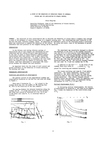
The general outline of the experimental roadway and
investigation boreholes at the Dai-Tun coal mine are shown
in Figure 1.
There were 6 boreholes (S .... S ) placed in the
roadway which was over the middle of the working face
No. 8111 in the direction of the face advance.
The spacing between the adjacent boreholes along the
roadway was 8m. 3-5 plugs were placed in each borehole
and these were placed at intervals of 5-10, 10-15 and
15-20m above coal seam No. 8, to intercept beds of
interest.
The experiment was essentially designed to observe
the behaviour of the floor in the roadway overlying
coal face No 8 111 with precise level measurement, and
to determine the relative displacement between the plugs
and the floor in this roadway through the multi-wire
boreholes. The roadway was 178m deep and coal face
No. 8111 was 115m long and inclined at 25 . Its
extracted height was 2m. The vertical distance between
the coal seam No. 8 and the roadway was 24.78m.
In addition to the borr
1
--
1
-
roadway there were other su
on the floor of the
points J.
'15
placed for levelling and traverse surveying.
The strata overlying coal seam No. 8 are mainly
sandstones. The lowest sandstones, having a total
thickness of 10m, which overlie the coal seam are
inherently weak so that they readily fracture during
mining operations. They contain frequent natural
weakness planes and partings. Above the immediate roof
there are four stronger strata of sandstones having
thicknesses of 4.05, 2.6, 4.6 and 2.5m.
Vertical displacement (V.D.)
In discussing vertical displacements, the results
of measurements at boreholes S are taken as an example.
Fig. 2 shows the behaviour of the inter-strata plugs
in S .
Fig. 1 Fig. 2
13
2. The form of the curves is similar to a negative
exponent curve and can be expressed by:
b
w W (1 - e "
aZ
)
÷ m
where W is the vertical displacement at distance X from
face,
and W is the displacement at distance L from face,
m
where the variation of this curve is just stable.
X
Æ = —, a and b are two coefficients, which are
closely related to the mechanical properties of the overlying
strata and the interval between the working coal
seam and the strata being investigated.
An example of this curve in the 24.78m vertical
interval above the working coal seam is shown in the
following table:
Æ -ã- 0.1 0.2 0.3 0.4 0.5 0.6 0.7 0.8 0.9 1.0
measured
value 12 50 200 350 475 600 700 750 800 825
(mm)
calculated
value 14.6 74.4183 324 473 604 703 765 800 816
(mm)
In this example L = 50m, W = 825mm.
m
According to this curve, the distribution of its
gradient is an abnormal curve. On the basis of the
mechanical characteristics of these curves, the overlying
strata can be divided into three zones (see Figure 2)
along the direction of face advance.
1. Zone ab-abutment pressure influence (API or
A) zone.
The strata in this zone is supported by the influence
of the working coal seam and the vertical displacement of
the plugs is very slight, and usually, but not always, a
slight negative magnitude occurred. This was always less
than 40mm.
The vertical displacement of the point b was
slight, even of the lower plugs (5-10m from the coal
seam), until the face was 4-8m past the borehole.
2. Zone bc-Bed separation (BSor B) zone.
When the influence of the working coal seam is
removed the displacement rate of the points increases
rapidly. The plug displacement rates in borehole S
are shown as follows :
The interval from
plug to the working
seam (m)
The max. displacement
rate of the plug
(mm/m)
The average displacement
rate of the plug
(mm)
6-10
180
10-15
100
15-20
70
80-100 60-80 55
25
50
45
This indicates that the displacement rate of the
overlying bed is not as fast as its underlying bed, i.e.
> V >
p
3
In this zone the strata groups are separated from
each other.
3. Zone_cd-consolidâtion (C) zone.
In this zone the separated strata are reconsolidated
and the rate of displacement of the plugs in boreholes
is as follows:
The interval from
plug to the working 6-10 10-15 15-20 25
coal seam (m)
The average rate of
displacement (mm/m) 18.5 18.4 22.1 23.5
Fig. 3
14
3. The phenomenon is the opposite to that in separation
zone be, i.e.
Í < Í < v <; V
Fig. 3 shows the vertical displacement of all the
inter-strata plugs placed in the six boreholes.
The behaviour of the strata can be expressed
through the variation of the linear gradient between the
pairs of plugs in adjacent boreholes. The example
for S^-S2 is shown in the following table.
Date of the
measurement
The gradient
for the level
6-10m (%)
25th
Mar.
1st 6th
Apr. Apr.
12 100 72
15th
Apr.
33
1st 5th
May May
30 24
The linear gradient of S^-S at the same date (1st
Apr.) for the different intervals from the working coal
seam is expressed below:
The interval
from plug to
working coal
seam (m)
The gradient
of the line
(%)
At the
roof
123
5-10 10-15 15-22 25
100 54 24 10
Horizontal displacement (H.D.)
The horizontal displacement was measured only for the
points placed in the floor of the roadway by theodolite.
Fig. 4 shows the horizontal displacement path of the
points. It illustrates that when the roadway is undermined,
the movement at the beginning is in a direction
opposite to that of the face advance and then after a
time the displacement changes to the direction of face
advance. At the same time a horizontal displacement occurs
in the direction of rise of the seam inclination.
Y I
Fig. 6 shows the displacement path in the vertical
plane along the direction of face advance. In this
figure it can be seen that the final position of the
point always overpasses the original space by 100-200mm.
From this data, it can be seen that the intermediate
friction between the strata is insufficient to
resist horizontal displacement.
Analysis
From the above results, Fig. 7 can be put forward
to illustrate the situation which arises as the overlying
strata are undermined. In Fig. 7 the lower
immediate roof caves irregularly into the goaf area.
Above it are stronger strata (main roof), which are
broken into regular blocks with the advance of the coal
face. These regular blocks may be interlocked and grade
into the subsurface strata.
à //1»f»i»V!»i»tVTv
!
/
it WëmÊÊÈ^
Fig. 7
The weight of the higher layers of overlying strata
are supported by a system of "working coal seam - waste
caved blocks" and the lower layers are supported by a
system of "working coal seam - roof support - waste caved
materials".
For this reason, in order to develop a "structural"
description for the support of overlying strata, the
influence of the roof support resistance on the higher
stronger strata should be ignored. From an engineering
standpoint, the overlying strata can be divided into
several groups.
The lower bed of every group is t h e strongest and
thickest bed (e.g. sandstone or limestone and others).
The weak strata which overlie this bed can be considered
as a load acting on this stronger bed and as an intermediate
supporting-layer for the overlying group strata.
For example, the strata shown in Fig. 7 can be
divided into 3 groups (that is I, II and III). The
interlocked space between the adjacent blocks of the
stronger bed was determined by the characteristic of
its vertical displacement curve. For example, when
the curve was bending concave downwards, the interlocked
space was at the bottom of the blocks and in the
opposite case, i.e. bending concave upwards, the interlocked
space was at the head of the blocks.
Fig. 4 Fig. 5
From this datum, the displacement path in the vertical
plane along the seam inclination can be obtained as in
Fig. 5. In Fig. 5 it can be seen that the path of the
point is just normal to the stratification of the worked
^oal seam.
3
c
J ,
Fig. 6
STRUCTURAL MODEL
Assumptions
On the basis of the foregoing statement the
following assumptions can be made to build a "structural"
model.
1. Every stronger bed in every group stata is
assumed to be a "structural" formation.
Thus, in group strata I, as shown in Fig. 7, the
surface deposit is assumed to behave like a
uniform boundary load under its own weight,
which acts on the stronger bed. For the lower
group strata the load acting on the stronger
bed will not be uniform.
2. Because the stronger bed undermined by the
working coal face has been separated into a
series of regular blocks, it is assumed that
the regular blocks can be considered as the
15
4. elements of the structural formation, and its
overlying weak strata as the load acting on
this structural formation.
3. Considering the conditions in interbed separation
zone be, there is no resistance from the blocks
in this zone to the higher overlying strata.
4. Because the intermediate friction between strata
cannot resist the horizontal deformation of the
strata, the weak strata between two adjacent
stronger beds can be assumed to act as a series
of columns to support overlying strata and to
load the underlying strata.
Then, considering these conditions, the structural
formation of Fig. 7 can be designated as in Fig. 8.
Where ^R^|is the column matrix of the force;
^M^Jis the column matrix of the moment;
/A.sis the matrix of coefficient.
From this matrix, the horizontal thrust acting on
the blocks can be calculated by the following formula:
2 rh. -V-—— S. + 2(n.-n.+n -n..) 1 T. = Q. L L. il i2 ox
i3 i4 J é
ic
ÉÏ
If it is assumed that the gradient of a pair of
adjacent blocks is the same, i.e. n ^ = n^S
ç
÷3
= n
i4>
then the approximate value of the horizontal thrust can
be obtained as follows:
Fig. 8
Model Calculation
It is now possible to analyse the interaction of
forces in every structural formation as shown in Fig. 9.
WjQîi mfcQfc * i , Q i3 n^(fr *;,á<9
ÎRî, ÎRiz · ÎRî» fr* ]Eis
7/ , - ô · mrr-r-r-rrrr-rj ß Ii ÃÉ J H Ô II
L. Q.
ô - ßï ßï T
i 2(h. -S. )
ÉÏ ÉÏ
This means the magntidue of T. depends only on the
physical and geometrical characteristics of the block B.
The approximate value of the other unknown forces
of the "structural" model can be calculated as follows:
(R.) º = 0 (R.) = Q.
é o-l é o-o ÉÏ
n., L. Q.
R. º = m. Q. - il ßï ßï
1 1 1 11 1
h. - s .
1 ÉÏ
n., L. Q.
il ßï ßï
Î2 i2
x
i2 h. - S.
1 ÎO
n._ L. Q.
é3 ßï ßï
i3 i3
x
i3 h. - S.
1 ÎO
Fig 9
The symbols which appear in the subsequent analysis
are given below:
A.B.CD - The symbols of blocks.
Ô - Lateral thrust of the blocks.
R - Resistance of the underlying
strata and the shear force
between the adjacent blocks.
q - Uniform load per unit length,
per unit width of the block.
Q - The weight of a block in a group
strata.
L - Length of the block.
and - The relative displacement from
one end to another of a block.
h - Thickness of the bed.
ç - Gradient of the block.
m - Loaded coefficient of the blocks.
In order to represent and distinguish every bed and
every block, to every symbol there is a subscript. For
example in 'H' means that the first subscript
represents the number of the seam and the second one is
the number of the block along the direction to the goaf
area.
Taking the bed, number i, for the calculation (Fig. 9)
the following abbreviated matrix equation can be obtained:
n.« L. Q.
é3 ßï ßï
i4 i4
x
i4 h. - S.
1 ÉÏ
From these formulae, some interesting results can
be obtained, as follows:
1. The weight of the strata blocks in the inter-bed
separation zone be is loaded almost on the
abutment of the working coal seam.
2. The shear force (R.)rt , between the block  and
é 0-1
C is equal to zero. The interlocked space
0-1 is like the top of the "half arch" for
every "structural" formation.
3. The maximum shear force in the structural model
occurs in the interlocked space 0-0, i.e.
between blocks A and B, and its value is equal
to the total weight of the block B.
Conditions required for equilibrium of the structural
model
From the standpoint of roof control, it follows
that in the inter-bed separation zone be, degradation
between adjacent blocks should not be allowed to occur.
The safety factor can be considered in the lighï:
of the relation of the friction force to shear force
at the interlocked space. If the shear force exceeds
the friction force, sliding between block A and  will
occur along the crack and the roof will collapse
unless additional support is provided.
A simple method to analyse possible sliding along
the cracks is to resolve the resultant of the horizontal
thrust T. and the shear force (R.) into components,
é é o-o
normal and parallel to the crack surface.
16
5. Hence, the conditions, required for roof control,
can be expressed in the following formula:
T.. t «Ñ - È) >(R.)
1 g » é o-o
h. S.
i.e. L. > 2 Ë ~ *°
ßï tg{(f - È)
If we take è = 0°, tg<f>= 1, > 2ÏU, the structural
formation in the strata can be determined.
All the previous analyses are based on the assumption
that the coal face is always moving forward. So that
the "structural" formation of the strata is always
changing with the advance of the face, which can be shown
in Fig. 10.
r L. .tg(d>- È) ]
P
> * h . r . W + M " 2(h. - S. ) K o '
TM /
L é ßï
Where Eh represents the total thickness of the
stratified immediate roof (in the caving block), W is
the width of the working area and r is the unit weight
of the rock.
Thus, the density of the resistance of the supports
1 S:
ñ i r ï h r y «Ìç Q j , . ô / »
2
P
*
Ó 1 À
·
Ã
·
+ 2
2(h. - S. ) J M"
Here Ñ and ñ are approximate values for designing
the resistance of the support in a longwall working
area.
Besides the aforesaid application, some other
phenomena in ground subsidence and in roof pressure can
be explained by this model.
CONCLUSIONS
On the basis of measurement from inter-strata
plugs in the working area in Dai-Tun coal mine, the
vertical displacement of the plugs, relative to the
coal face, can be assumed to be a negative exponent
curve. The distribution of the gradient dW /dZ of this
cSirve is an abnormal curve.
Fig. 10
Fig. 10 shows that block A will be out of balance
when it was broken, and under the influence of the moment
block A will rotate until the foregoing structural
formation appears again
In order to prevent the appearance of steps and falls
in block A, enough resistance must be provided to act on
block A. Unless there is enough friction force in the
interlocked space, it must be resisted by means of
supports in the working area.
APPLICATION
From the previous analysis, the immediate roof is the
caving block with lateral expansion. Above the immediate
roof the caved material in the goaf provides the overlying
strata with support and a thrust force parallel to the
strata is created by this buttressing forming a structural
unit in the strata.
Now let Ñ represent the resistance to be provided by
face supports to prevent degradation of the immediate roof.
Then it must be equal to:
P„ + T. . tg (<P- è) >(R.) + Q.
R é • é o-o ic
If (R.) is equal to the maximum, it will be equal
é o-o
n
to: Q.o> i.e.:
P R + T. . t g « f - è) >2Q.o
then
> 2
L
i o '
t R( - È)
2(h. - ¾7¾
IO
If the calculated value of P^ is negative, this means
that the conditions required for equilibrium in the stratum
are perfect and the P^ may not be needed.
If the supports must have sufficient resistance to
prevent the immediate roof from falling, the resistance of
the support per unit length of the face can approximately
be calculated as follows:
Depending on the strength of the overlying strata,
these can be divided into several groups. The lowest
layer of every group is ,a stronger and thicker bed.
With the advance of the face, between the adjacent
blocks in the bed, a lateral thrust will occur creating
a structural formation in the bed. These structural
formations are supported by a system of "working coal
seam-roof support-caved material in the goaf" and a
system of "working coal seam-caved or broken blocks underlying
strata". The rock masses of the overlying strata
in the working area can then be divided into three zones.
On the basis of approximate calculations, the value
of the force acting on the block  can be shown to be
independent of the vertical stress distribution in the
goaf area.
According to calculations, the total weight in the
inter-bed separation zone is loaded almost on the
abutment of the working coal seam. From the formation,
the space in which the shear force is maximum, can be
obtained and the conditions, required for equilibrium
can be analysed.
With the advance of the coal face, the process
"equilibrium-dynamic equilibrium-equilibrium again"
occurs in every structural formation.
In order to prevent the degradations of block A
(steps and falls), there should be enough resistance
(which can be approximately calculated) from the face
supports.
REFERENCES
Chien Ming-Gao "Conditions Required for Equilibrium of
overlying strata at working areas". Journal of China
Institute of Mining Technology. 1981.2.
Li hon-zhang, Chien Ming Gao "A study of the system of
the exploitation in upward order in Dai-Tun coal mine",
1981.
King, H.I., Whittaker, B.N. and Batchelor, A.S. "The
effects of interaction in mine layouts". 5th Inter.
Strata Control Conf. 1972, London.
Proceedings of European Congress on Ground Movement.
1957.
Wright, F.D. "Roof control through beam action and
arching." SME Mining Engineering Handbook, 1973.
17