Satellite communications by dennis roddy (4th edition)
•Download as DOCX, PDF•
5 likes•9,177 views


Recommended
More Related Content
What's hot
What's hot (20)
Viewers also liked
Viewers also liked (20)
Similar to Satellite communications by dennis roddy (4th edition)
Similar to Satellite communications by dennis roddy (4th edition) (20)
Recently uploaded
Recently uploaded (20)
Satellite communications by dennis roddy (4th edition)
- 1. 268 Chapter Nine Please purchase PDF Split-Merge on www.verypdf.com to remove this watermark. results usually give a good indication of what to expect with an arbitrary signal. Example 9.2 A test tone of frequency 800 Hz is used to frequency modulate a carrier, the peak deviation being 200 kHz. Calculate the modulation index and the bandwidth. Solution f = 200 = 250 0.8 B = 2(200 + 0.8) = 401.6 kHz Carson's rule is widely used in practice, even though it tends to give an underestimate of the bandwidth required for deviation ratios in the range 2 < D < 10, which is the range most often encountered in practice. For this range, a better estimate of bandwidth is given by BIF = 2(AF + 2FM) (9.4 ) Example 9.3 Recalculate the bandwidths for Examples 9.1 and 9.2. Solution For the video signal, Bif = 2(10.75 + 8.4) = 38.3 MHz For the 800 Hz tone: Bif = 2(200 + 1.6) = 403.2 kHz In Examples 9.1 through 9.3 it will be seen that when the deviation ratio (or modulation index) is large, the bandwidth is determined mainly by the peak deviation and is given by either Eq. (9.1) or Eq. (9.4). However, for the video signal, for which the deviation ratio is relatively low, the two estimates of bandwidth are 29.9 and 38.3 MHz. In practice, the standard bandwidth of a satellite transponder required to handle this signal is 36 MHz. The peak frequency deviation of an FM signal is proportional to the peak amplitude of the baseband signal. Increasing the peak amplitude results in increased signal power and hence a larger signal-to-noise ratio. At the same time, AF, and hence the FM signal bandwidth, will increase as shown previously. Although the noise power at the demodulator input is proportional to the IF filter bandwidth, the noise power output after the demodulator is determined by the bandwidth of the baseband filters, and therefore, an increase in IF filter bandwidth does not increase output noise. Thus an improvement in signal-to-noise ratio
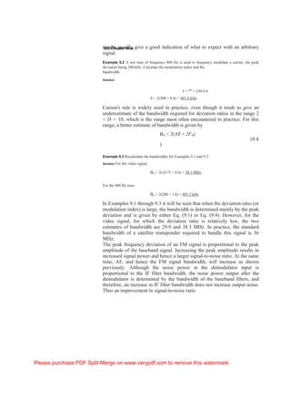
- 2. Please purchase PDF Split-Merge on www.verypdf.com to remove this watermark. Analog Signals 269 is possible but at the expense of an increase in the IF bandwidth. This is the large-amplitude signal improvement referred to in Sec. 9.6 and considered further in the following section. 9.6.3 FM detector noise and processing gain At the input to the FM detector, the thermal noise is spread over the IF bandwidth, as shown in Fig. 9.10a. The noise is represented by the system noise temperature Ts, as will be described in Sec. 12.5. At the input to the detector, the quantity of interest is the carrier-to-noise ratio. Since both the carrier and the noise are amplified equally by the receiver gain following the antenna input, this gain may be ignored in the carrier- to-noise ratio calculation, and the input to the detector represented by the voltage source shown in Fig. 9.10b. The carrier root-mean-square (rms) voltage is shown as Ec. SnS£B|F — H l^Sf iI| |t.i | f , +w (a I (b) Figure 9.10 (a) The predetector noise bandwidth BN is approximately equal to the IF bandwidth BIF. The LF bandwidth W fixes the equivalent postdetector noise bandwidth at 2W. Sf is an infinitesimally small noise bandwidth. (b) Receiving system, including antenna represented as a voltage source up to the FM detector.
- 3. 270 Chapter Nine Please purchase PDF Split-Merge on www.verypdf.com to remove this watermark. The available carrier power at the input to the FM detector is E2 /4R, and the available noise power at the FM detector input is kTsBN (as explained in Sec. 12.5), so the input carrier-to-noise ratio, denoted by C/N, is C E2 C = -------- c ---- ------------- (9.5) N 4RkTs BN When a sinusoidal signal of frequency, fm, frequency modulates a carrier of frequency, fc: The instantaneous frequency is given by fi = fc + Afsin 2wfmt, where Af is peak frequency deviation. The output signal power following the FM detector is Ps = AAf2 (9.6) where A is a constant of the detection process. The thermal noise at the output of a bandpass filter, for which fc >> BN has a randomly varying amplitude component and a randomly varying phase component. (It cannot directly frequency modulate the carrier, the frequency of which is determined at the transmitter, which is at a great distance from the receiver and may be crystal controlled). When the carrier amplitude is very much greater than the noise amplitude the noise amplitude component can be ignored for FM, and the carrier angle as a function of time is 9(t) = 2ft + $n(t), where $n(t) is the noise phase modulation. Now the instantaneous frequency of a phase modulated wave in general is given by Mi = dQ(t)/dt and since Mi = 2^fi, the equivalent FM resulting from the noise phase modulation is feq.n = fc + ~~~ (9.7) 2^ dt What this shows is that the output of the FM detector, which responds to equivalent FM, is a function of the time rate of change of the phase change. Now as noted earlier, the available noise power at the input to the detector is kTsBN and the noise spectral density, which is the noise power per unit bandwidth just kTs. A result from Fourier analysis is that the power spectral density of the time derivative of a waveform is (2^f )2 times the spectral density of the input. Thus the output spectral density as a function of frequency is (2wf)2 kTs. The variation of output spectral noise density as a function of frequency is sketched in Fig. 9.11a. Since voltage is proportional to the square root of power, the noise voltage spectral density will be proportional to frequency as sketched in Fig. 9.116. Figure 9.11a shows that the output power spectrum is not a flat function of frequency. The available noise output power in a very small band df would be given by (2wf)2 kTshf. The total average noise output power