Strategies for Landing an Oracle DBA Job as a Fresher
A+ cheat sheet
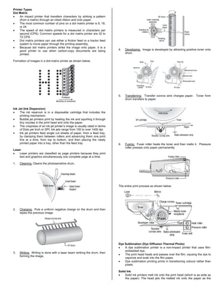
1. Printer Types
Dot Matrix
• An impact printer that transfers characters by striking a pattern
(from a matrix) through an inked ribbon and onto paper.
• The most common number of pins on a dot matrix printer is 9, 18,
or 24.
• The speed of dot matrix printers is measured in characters per
second (CPS). Common speeds for a dot matrix printer are 32 to
72 CPS.
• Dot matrix printers can use either a friction feed or a tractor feed
system to move paper through the printing assembly.
• Because dot matrix printers strike the image onto paper, it is a
good printer to use when carbon-copy documents are being
printed.
Formation of images in a dot-matrix printer as shown below.
Ink Jet (Ink Dispersion)
• The ink reservoir is in a disposable cartridge that includes the
printing mechanism.
• Bubble jet printers print by heating the ink and squirting it through
tiny nozzles in the print head and onto the paper.
• The crispness of an ink jet printer’s image is usually rated in terms
of Dots per Inch or DPI. Ink jets range from 150 to over 1400 dpi.
• Ink jet printers feed single cut sheets of paper, from a feed tray,
by clamping them between rollers and advancing them one print
line at a time, from top to bottom, and then placing the newly
printed paper into a tray, other than the feed tray.
Laser
• Laser printers are classified as page printers because they print
text and graphics simultaneously one complete page at a time.
1. Cleaning: Cleans the photosensitive drum.
2. Charging: Puts a uniform negative charge on the drum and then
wipes the previous image.
3. Writing: Writing is done with a laser beam striking the drum, then
forming the image.
4. Developing: Image is developed by attracting positive toner onto
drum.
5. Transferring: Transfer corona wire charges paper. Toner from
drum transfers to paper.
6. Fusing: Fuser roller heats the toner and then melts it. Pressure
roller presses onto paper permanently.
The entire print process as shown below.
Dye Sublimation (Dye Diffusion Thermal Photo)
• A dye sublimation printer is a non-impact printer that uses film-
embedded dye.
• The print head heats and passes over the film, causing the dye to
vaporize and soak into the film paper.
• Dye sublimation printing prints in transitioning colours rather than
pixels.
Solid Ink
• Solid ink printers melt ink onto the print head (which is as wide as
the paper). The head jets the melted ink onto the paper as the
2. paper passes by on the print drum (similar to the laser printing
process).
• The head takes as long as 15 minutes to heat prior to printing.
Thermal
• A thermal printer is a non-impact printer that uses heat to cause a
reaction on specially treated paper.
• Monochrome thermal paper is chemically treated to darken where
heated (photosensitive). Many cash registers use this type of
printer for creating receipts.
• Colour thermal paper is chemically treated to absorb colour from
a ribbon where heated.
• Ink is applied via the ribbon in a similar manner to a solid ink
printer.
• The colour system used by thermal printers is CMYK (Cyan,
Magenta, Yellow, and black).
• The paper must make one pass for each application of a different
colour.
• Colour thermal printers are very expensive, high quality, and
operate quietly.
Printer Configuration Facts
Print Server: is responsible for managing the flow of documents from
the queue to the printer. When the printer is ready, the print server
takes the next document out of the queue and sends it to be printed.
Printer: A virtual device (logical software entity) inside the print server
that can be configured to send output to a printing device. The printer
is made up of the print driver, the printing device, and the spooler.
Print Device: The physical device connected to the print server where
print output occurs.
Print Driver: The software that allows the printer to communicate with
the print device. Printer drivers provide the following support functions:
• Translate data into a recognizable form for the given printer.
• Manage graphics via graphics drivers, converting graphics into
the appropriate printer commands.
• Allow management of the print job by displaying print and printer
properties in the operating system.
When a print job is sent to the printer, the printer driver:
1. Formats the print job and creates a file of commands the printer
understands. The file is in a specific format called a printer
language (also called page-description languages).
2. The file is then sent to the printer where it is stored in the printer's
memory.
3. The printer's formatter board and control circuitry then read the
commands in the file and translate them into physical actions by
the printer.
Print Queue: The portion of the hard drive where print jobs are stored
before going to the print device.
Print Spooling: In print spooling, documents are loaded into a buffer
(usually an area on a disk), and then the printer pulls them off the
buffer at its own rate. Because the documents are in a buffer where
they can be accessed by the printer, the user is free to perform other
operations on the computer while the printing takes place in the
background. Spooling also lets users place a number of print jobs in a
queue instead of waiting for each one to finish before specifying the
next one.
Printer Port: The means by which a print device connects to a print
server (parallel port, serial port, or to the printer's NIC). Traditional
parallel ports are quickly being replaced by USB ports for printing
devices. In this respect, many printers can be configured in the same
way that most plug and play devices are.
All parallel connections must adhere to the IEEE standard 1284. You
should look at your printer configuration to see which mode your printer
requires. The five modes addressed in the IEEE standard are:
• Nibble
• Compatibility
• BYTE
• EPP
• ECP
Printer Languages
Language Description
Escape Codes Used to control dot matrix printers.
Printer Control
Language (PCL)
Hewlett-Packard has created several versions of a
printer control language called PCL. Many modern
printers understand PCL.
PostScript
Adobe created a printer language called PostScript
that easily handles scaling of certain fonts and
images.
Troubleshooting Printers
If the printer prints, but the printout quality is poor, check the following:
• Check ribbon, ink, and toner levels.
o For dot matrix printers, printer images become faint when
the ribbon needs to be replaced. Also, ensure that there isn’t
too much of a gap between the printer head and the paper.
o For inkjet printers, if letters have missing lines, use the
printer's automatic cleaning feature. If this doesn't work,
replace the printer cartridge. For missing or incorrect
colours, verify ink levels.
o For laser printers with missing lines, try shaking the toner
cartridge to distribute the toner evenly. If lines are still
missing, or if extra characters appear, you might need to
have the printer cleaned or some internal components
replaced.
• For laser printers:
o A dirty primary corona wire can cause a vertical stripe down
the print job because that part of the OPC drum is not being
charged by the charge corona.
o A dirty secondary corona wire could cause the same
problem because the charge is not being applied to part of
the paper.
o If toner is not sticking to the paper, check the transfer rollers.
o A faulty static eliminator strip might cause paper jams
because the paper will stick to the components inside the
printer.
• For newer laser and inkjet printers, calibrate the printer (perform a
self test). Calibration fixes blurry text or incorrect colours.
• If the text appears garbled, make sure the proper printer driver is
used.
• If the page only prints part way through (and the rest of the page
is blank), you might need to upgrade the memory on the printer or
check the print server settings.
• Check the pickup rollers; if paper is not being fed through the
printer properly.
Scanners
• Scanners use a light source and a Charge-Coupled Device (CCD)
that captures light and converts it to digital data.
• Twain is a scanner language that bridges the different scanners to
a common form that can be interpreted by typical graphics
software applications.
Below is a typical scanner and its components
Serial, Parallel IEEE 1284 & PS/2 Components
Connector Description
Serial Connector
• The maximum length for an RS-232
serial cable is 50 feet.
Parallel Connectors
• There are two common types of
parallel cables:
3. • An IBM Printer cable is a uni-
directional cable with a 25-pin male
DB-25 connector at one end (top
graphic on the left) and a 36-
conductor male Centronics
connector at the other end (bottom
graphic on the left).
• IEEE 1284 is a newer, bi-directional
cable more commonly used.
Connectors used are similar to the
IBM printer cable, but with different
connector genders possible.
o The maximum specified length
is 10 meters (approx. 30 feet).
o Data can be transferred at up
to 2 MB/s.
You should know the following facts
about parallel connectors:
• The IEEE 1284 specifies a daisy
chaining standard that allows up to
eight devices to be connected to a
single parallel port.
• Enhanced parallel port (EPP) is an
IEEE 1284 mode that specifies a
half-duplex, bi-directional standard
used by non-printing devices to
send large amounts of data to the
host.
• Extended capabilities port (ECP) is
an IEEE 1284 mode that specifies a
half-duplex, bi-directional standard
that allows greater transfer speeds
and compression.
PS/2 Connectors
PS/2 connectors are 6-pin mini-din
connectors. The connector's sleeve has a
notch to ensure proper alignment when
inserted into the port and to prevent the
pins in the connector from being bent.
• The keyboard connector is typically
towards the outside of the
motherboard faceplate.
• The PC99 standard uses purple for
the keyboard and green for the
mouse.
Redundant Array of Independent Disks
RAID 0: striped set (min 2 disks) w/o parity and no fault tolerance. Any
disk failure destroys the array.
RAID 1: mirrored set (min 2 disks) w/o parity. Provides fault tolerance
from disk errors and single disk failure.
RAID 3 & RAID 4: striped set (min 3 disks) w/ dedicated parity. This
mechanism provides an improved performance and fault tolerance
similar to RAID 5, but with a dedicated parity disk rather than rotated
parity stripes.
RAID 5: striped set (min 3 disks) w/ distributed parity. Distributed
parity requires all but one drive to be present to operate; drive failure
requires replacement but the array is not destroyed by a single drive
failure.
RAID 6: striped set (min 4 disks) w/ dual distributed parity. Provides
fault tolerance from two drive failures; array continues to operate with
up to two failed drives.
PC Card Types
PCMCIA dimensions, excluding thickness, are the same for each type
of card and each card type has a 68-pin connector.
Type 1 PC Cards generally contain computer memory, Type 2 PC
Cards are used for network adapters and Type 3 cards generally
contain disk storage.
USB
Version Speed Data Transfer Rate
(Mbps)
Max Cable Length
(meters)
1.0 Low 1.5 Mbps 3m
1.1 Full 12 Mbps 5m
2.0 High 480 Mbps 5m
Note: You can connect up to 127 USB devices to a single USB port.
USB Connectors
Connector Description
A Connector
Rectangular connector that generally plugs
directly into the computer or a hub.
B Connector
D-shaped connector that plugs into a hub,
printer, or other peripheral device to connect
the device to the computer.
Most USB cables have an A connector on
one end (to connect to the computer or hub)
and a B connector on the other end (to
connect to the device)
Mini Connector (4 pin) Small square connector designed to plug in to
devices with mini plugs such as a digital
camera. Most USB cables with a mini
connector have an A connector on the other
end to connect to the computer
Mini Connector (5 pin)
Small connector designed to plug in to
devices with mini plugs such as a digital
camera.
Self Powered
Devices that rely on their own power supply (in other words, you plug
them into an AC outlet) are called self-powered devices. All devices
that draw more than 500 mA of power are required to be self-powered.
Bus Powered
USB cables have wires to carry both power and data. Bus-powered
devices get their power from the USB cable. Bus-powered devices are
classified as low-powered or high-powered devices depending on the
amount of power they draw from the USB bus.
• Low powered devices use 100 mA or less
• High-powered devices use between 100 and 500 mA
Like USB devices, USB hubs can be bus-powered or self-powered.
You cannot connect high-powered devices to a bus-powered hub (you
can only connect low-powered or self-powered devices to a bus-
powered hub). Therefore, self-powered hubs that provide 500 mA per
port are recommended to ensure an adequate power supply to all bus-
powered devices that you may wish to connect to the hub.
Ethernet IEEE 802.3
Name Cabling Speed
Mbps
Type Max
Length
10Base5 Thicknet Coax Thick 10 Digital 500 M
10Base2 Thinet Coax Thin 10 Digital 185 M
10BaseT Star Bus Twisted Pair 10 Digital 100 M
100BaseTX Star Bus Twisted Pair 100 Digital Varies
10BaseF Fiber Optic 10 Digital Varies
100BaseF Fiber Optic 100 Digital Varies
4. Firewire IEEE 1394
Version Description
1394 • Supports speeds of 100, 200, 400 megabits per
second
• Maximum cable length is 4.5 meters (15 feet)
• Can connect up to 63 devices on one IEEE 1394 bus
1394.A • Clarifies and enhances the original standard
1394.B • Under development to support speeds of 800, 1600,
and 3200 megabits per second
• Maximum cable length is 100 meters (328 feet)
1394.3 • Supports peer-to-peer data transmission
• Devices like scanners and digital cameras can send
data directly to a printer (no computer involvement
required)
Wireless IEEE 802.11
Standard
Specification 802.11a 802.11b 802.11g
Frequency 5.75-5.85 GHz 2.4-2.4835 GHz 2.4-2.4835 GHz
Speed 54 Mbps 11 Mbps 54 Mbps
Range 150 ft. 300 ft. 300 ft.
Backwards-
Compatibility
NA No With 802.11b
Wireless Architecture
Ad Hoc:
• Works in peer-to-peer mode without an Access Point (AP)
• Uses a physical mesh topology with up to four hosts
Infrastructure:
• Employs an AP that functions like a hub on an Ethernet network
• Uses a physical star topology and can easily add hosts without
increasing administrative efforts (scalable)
Service Set Identification (SSID): The SSID identifies a network and
logically groups all devices onto a single network. The SSID is
commonly referred to as the network name.
Wireless Equivalent Privacy (WEP): WEP is an encryption mechanism
designed to provide wireless networks the same type of protection that
cables provide on a wired network. Only users with the correct WEP
key are allowed to authenticate.
Wi-Fi Protected Access (WPA): WPA is a security mechanism that
attempts to address the weaknesses of WEP by assigning unique keys
to each host and changing the dynamic keys periodically. WPA offers
greater protection than WEP.
Infrared (IrDA)
• Infrared uses invisible light waves for communication.
• Is a line-of-sight medium.
• Communicates at 9600 bps up to 4 Mbps and uses the resources
of a COM port.
• Works best for devices within 1 meter, but can operate up to 30
meters in areas without ambient light interference
Bluetooth
• Bluetooth uses radio waves for communication.
• Uses ad hoc connections between devices to create personal
area networks called piconets. A piconet can have up to 7
devices, and each device can participate in multiple piconets at
the same time.
• Operates in the 2.4 GHz frequency range and uses adaptive
frequency hopping (AFH). It automatically detects other devices in
the area and avoids the frequencies used by those devices. It can
switch between 79 channels to avoid interference.
• Transmits at up to 3 Mbps. The maximum distance depends on
the device class:
o Class 3 devices transmit up to 1 meter.
o Class 2 devices transmit up to 10 meters.
o Class 1 devices transmit up to 100 meters.
• Class 2 devices are the most common.
• Can be used for both voice and data signals.
Troubleshooting Networks
If the connection shows that the cable is unplugged, check the status
indicator lights on the network card.
• The link light indicates a valid connection to the network.
o A solid green light indicates a good physical connection.
o On some switches, an amber link light indicates a slower
connection (such as 10 Mbps compared to a 100 Mbps
connection which might show a green light).
• The activity light indicates that the connection is being used.
o This light should flash periodically, even if you are not
currently sending data over the link. This is known as a
heartbeat or keepalive signal that lets the NIC know it has an
active connection.
o The light flashes more constantly as data is being sent.
If a single computer is having problems:
1. Make sure all cables are plugged in.
2. Swap the cable with one you know to be working.
3. Plug the computer into a different hub or switch port.
4. Troubleshoot or replace the network card.
If multiple computers are having a similar problem, then the problem is
likely with the hub, switch, or router.
Common Boot Errors Codes
1xx: Motherboard
2xx: RAM
301: Keyboard
4xx: Monitor
501: Video
601: Floppy
7xx: Math Coprocessor
9xx: Parallel Port
11xx: Serial Port
17xx: Hard Disk
Port Numbers
FTP: 20 (transfer) & 21 (listen)
SSH: 22
TELNET: 23
SMTP: 25
DNS: 53
DHCP: 68
HTTP: 80
POP3: 110
IMAP: 143
HTTPS: 443
Remote Desktop: 3389
Protocols
Protocol Description
HyperText
Transfer
Protocol
(HTTP)
HTTP is used by Web browsers and Web servers to
exchange files through the World Wide Web and
intranets. HTTP can be described as an information
requesting and responding protocol. It is typically used
to request and send Web documents, but is also used
as the protocol for communication between agents
using different TCP/IP protocols.
HyperText
Transfer
Protocol over
Secure Socket
Layer or HTTP
over SSL
(HTTPS)
HTTPS is a secure form of HTTP that uses SSL as a
sub layer for security.
HyperText
Markup
Language
(HTML)
HTML is a data format that is used to create hypertext
documents that can be viewed from multiple platforms.
Although HTML is not technically a programming
language, it has become a common language used for
programming information in a format that is readable by
web browsers. It consists of a series of tags that define
the attributes of displayed text and images.
Secure
Sockets Layer
(SSL)
SSL secures messages being transmitted on the
Internet. It uses RSA for authentication and encryption.
Web browsers use SSL (Secure Sockets Layer) to
ensure safe Web transactions. URLs that begin with
https:// trigger your Web browser to use SSL.
File Transfer
Protocol (FTP)
FTP provides a generic method of transferring files. It
can include file security through usernames and
passwords, and it allows file transfer between dissimilar
computer systems. FTP can transfer both binary and
text files, including HTML, to another host. FTP URLs
are preceded by ftp:// followed by the DNS name of the
FTP server. To log in to an FTP server, use:
ftp://username@servername.
Simple Mail
Transfer
Protocol
(SMTP)
SMTP is used to route electronic mail through the
internetwork. E-mail applications provide the interface to
communicate with SMTP or mail servers. SMTP is a
relatively simple, text-based protocol, in which one or
more recipients of a message are specified (and in most
cases verified to exist) and then the message text is
transferred.
5. Internet
Message
Access
Protocol
(IMAP)
IMAP is an e-mail retrieval protocol designed to enable
users to access their e-mail from various locations
without the need to transfer messages or files back and
forth between computers. Messages remain on the
remote mail server and are not automatically
downloaded to a client system.
Post Office
Protocol 3
(POP3)
POP3 is part of the TCP/IP protocol suite and used to
retrieve e-mail from a remote server to a local client
over a TCP/IP connection. With POP3, e-mail
messages are downloaded to the client.
Remote
Terminal
Emulation
(Telnet)
Telnet allows an attached computer to act as a dumb
terminal, with data processing taking place on the
TCP/IP host computer. It is still widely used to provide
connectivity between dissimilar systems. Telnet can
also be used to test a service by the use of HTTP
commands.
Secure Shell
(SSH)
SSH allows for secure interactive control of remote
systems. SSH is a secure and acceptable alternative to
Telnet.
Dynamic Host
Configuration
Protocol
(DHCP)
DHCP is a protocol used by networked computers to
obtain IP addresses and other parameters such as the
default gateway, subnet mask, and IP addresses of
DNS servers from a DHCP server. The DHCP server
ensures that all IP addresses are unique.
Domain Name
System (DNS)
DNS is a system that is distributed throughout the
internetwork to provide address/name resolution. For
example, the name www.mydomain.com would be
identified with a specific IP address.
TCP/IP
The suite of communications protocols used to connect
hosts on the Internet.
User Datagram
Protocol (UDP)
Programs on networked computers can send short
messages sometimes known as datagrams (using
Datagram Sockets) to one another. Datagrams may
arrive out of order, appear duplicated, or go missing
without notice. Avoiding the overhead of checking
whether every packet actually arrived makes UDP faster
and more efficient, at least for applications that do not
need guaranteed delivery.
IPX/SPX
IPX/SPX is the protocol suite used on legacy NetWare
networks.
• NetWare 3 and NetWare 4 use IPX/SPX by
default. However, both can be configured to use
TCP/IP.
• One way to configure a Microsoft client computer
to connect to a NetWare server running IPX/SPX is
to install the NWLink protocol software supplied by
Microsoft.
AppleTalk
AppleTalk is the protocol suite used by early Apple
Macintosh computers.
• AppleTalk over IP is the protocol for using
Appletalk on a TCP/IP network
NetBIOS
NetBIOS is the term used to describe the combination
of two protocols: Because NetBIOS is a non-routable
protocol, it was often combined with TCP/IP or IPX/SPX
to enable internetwork communications.
• NetBEUI is the native protocol of Windows
3.x/95/98/ME.
Windows
Internet Name
Service
(WINS)
WINS provides a centralized method of name
management that is both flexible and dynamic. A WINS
server automatically collects entries whenever a client is
configured with that WINS server’s address. In theory,
if DNS is available, WINS is only necessary if pre-
Windows 2000 clients or servers need to resolve
names.
Network Address Translation (NAT)
NAT refers to network address translation involving the mapping of
port numbers, allowing multiple machines to share a single IP address.
Networking Utilities
NSLOOKUP.EXE: enables you to verify entries on a DNS server.
PING.EXE: Sends a series of packets to another system, which in turn
sends back a response. This utility can be extremely useful for
troubleshooting problems with remote hosts.
TRACERT.EXE: enables you to verify the route to a remote host. The
results also include the number of hops needed to reach the
destination router.
Communication between hosts on a network generally takes one of
three forms:
• Simplex: one-way communication from a sender to a receiver.
• Half-duplex: two-way communication between two hosts.
Communication only travels in one direction at a time.
• Full duplex: two-way communication between hosts.
Communication can travel in both directions simultaneously.
Address Range Default Class Default Subnet Mask
1.0.0.0 to 126.255.255.255 A 255.0.0.0
128.0.0.0 to 191.255.255.255 B 255.255.0.0
192.0.0.0 to 223.255.255.255 C 255.255.255.0
224.0.0.0 to 239.255.255.255 D Multicast
240.0.0.0 to 255.255.255.255 E Reserved
169.254.0.1 to 169.254.255.254
Can’t contact
DHCP server,
APIPA
255.255.0.0
127.0.0.1 is a special purpose address reserved for use on each
computer. 127.0.0.1 is conventionally a computer's loopback address.
Network software and utilities can use 127.0.0.1 to access a local
computer's TCP/IP network resources. Messages sent to loopback IP
addresses like 127.0.0.1 do not reach outside to the local area network
(LAN) but instead are automatically re-routed by the computer's own
network adapter back to the receiving end of the TCP/IP stack.
UTP Cable Types
Type Connector Description
Phone
cable
RJ-11 Used to connect a modem to a phone jack in a
wall outlet to establish a dial-up Internet
connection. Has two pairs of twisted cable (a
total of 4 wires).
Cat 3 RJ-45 Designed for use with 10 megabit Ethernet or 16
megabit token ring.
Cat 5 RJ-45 Supports 100 megabit and 1 gigabit Ethernet and
ATM networking.
Cat 5e RJ-45 Similar to Cat 5 but provides better EMI
protection. Supports 1 and 10 gigabit Ethernet
(gigabit connections require the use of all four
twisted pairs).
Cat 6 RJ-45 Supports high-bandwidth, broadband
communications.
Twisted Pair & Coaxial Cables
Connector Description
RJ-11
• Has 4 connectors
• Supports up to 2 pairs of wires
• Uses a locking tab to keep
connector secure in outlet
• Used primarily for telephone wiring
RJ-45
• Has 8 connectors
• Supports up to 4 pairs of wires
• Uses a locking tab to keep
connector secure in outlet
• Used for Ethernet and some token
ring connections
F-Type
• Twisted onto the cable
• Used to create cable and satellite
TV connections
• Used to hook a cable modem to a
broadband cable connection
BNC
• Molded onto the cable
• Used in 10Base2 Ethernet networks
6. AUI
• DB15 serial connector
• Used in 10Base5 Ethernet networks
Coaxial Cable Types
Grade Uses
Resistance
Rating
RG-58
10Base2 Ethernet networking (also called
Thinnet)
50 ohms
RG-59 Cable TV and cable networking 75 ohms
RG-6 Satellite TV 75 ohms
RG-8
10Base5 Ethernet networking (also called
Thicknet)
50 ohms
Fiber Optic Facts
To connect computers using fiber optic cables, you need two fiber
strands. One strand transmits signals, and the other strand receives
signals. Fiber optic cabling is composed of the following components:
• The core carries the signal. It is made of plastic or glass.
• The cladding maintains the signal in the center of the core as the
cable bends.
• The sheathing protects the cladding and the core.
Multi-mode and single mode fiber cables are distinct from each other
and not interchangeable. The table below describes multi-mode and
single mode fiber cables.
Type Description
Single
Mode
• Transfers data through the core using a single light ray
(the ray is also called a mode)
• The core diameter is around 10 microns
• Supports a large amount of data
• Cable lengths can extend a great distance
Multi-
mode
• Transfers data through the core using multiple light
rays
• The core diameter is around 50 to 100 microns
• Cable lengths are limited in distance
Fiber Optic Connector Types
Type Description
ST Connector
• Used with single and
multi-mode cabling
• Keyed, bayonet-type
connector
• Also called a push in and
twist connector
• Each wire has a separate
connector
• Nickel plated with a
ceramic ferrule to insure
proper core alignment and
prevent light ray deflection
• As part of the assembly
process, it is necessary to
polish the exposed fiber
tip to ensure that light is
passed on from one cable
to the next with no
dispersion
SC Connector
• Used with single and
multi-mode cabling
• Push on, pull off
connector type that uses a
locking tab to maintain
connection
• Each wire has a separate
connector
• Uses a ceramic ferrule to
insure proper core
alignment and prevent
light ray deflection
• As part of the assembly
process, it is necessary to
polish the exposed fiber
tip
LC Connector
• Used with single and
multi-mode cabling
• Composed of a plastic
connector with a locking
tab, similar to a RJ-45
connector
• A single connector with
two ends keeps the two
cables in place
• Uses a ceramic ferrule to
insure proper core
alignment and prevent
light ray deflection
• Half the size of other fiber-
optic connectors
MT-RJ Connector
• Used with single and
multi-mode cabling
• Composed of a plastic
connector with a locking
tab
• Uses metal guide pins to
ensure it is properly
aligned
• A single connector with
one end holds both cables
• Uses a ceramic ferrule to
insure proper core
alignment and prevent
light ray deflection
Internet Connectivity
Method Description
PSTN (Public
Switched
Telephone
Network)
PSTN is an example of a circuit switched technology.
Each time a call is placed, it is assigned the next
available connection pathway to the other party. This
connection is lost at the end of the call. PSTN Internet:
• Uses a single POTS (Plain Old Telephone
Service) phone line with a modem.
• Uses a single channel on the line.
• Has common data transfer rates include 28.8
Kbps, 33.3 Kbps, 56 Kbps.
• Offers sufficient network connectivity for a
minimal investment.
• Is available virtually anywhere that regular voice
grade communications are available.
• Requires the destination host's phone number
(username and password are required at log on)
for configuring a dial-up connection.
• Cannot be used for voice and the Internet
concurrently.
DSL (Digital
Subscriber
Line)
DSL is a newer broadband digital service provided by
telephone service providers that operates using digital
signals over regular telephone lines. DSL Internet:
• Comes in many different varieties (such as
ADSL and HDSL).
• Sends digital signals over existing copper
telephone wire using multiple channels.
• Has one channel that is dedicated to phone line
data, with additional channels used for data.
• Can be used for voice and the Internet
concurrently.
• Requires a DSL router (or a cable modem) or NIC
attached (with USB or Ethernet) to the phone line.
• Requires filters (also called splitters) before the
phone with some implementations.
• Requires a location to be within a fixed distance
of network switching equipment.
ISDN
(Integrated
Services
Digital
Network)
ISDN is a digital service, running over a switched
network. ISDN Internet:
• Uses a switched network which includes 4-wire
copper telephone lines in a local loop and
standard telephone lines.
7. • Establishes a virtual circuit through dial-up before
communication (on-demand service).
• Supports most upper-level protocols
(communication protocols allow all media types to
transmit over the same line at high speeds).
Levels of service include:
BRI (Basic Rate Interface):
o 2 64-Kbps bearer (B) channels can transfer
data up to 128 Kbps (data compression
increases the data transfer rate). Only one B
channel is used during phone use reducing
maximum speed to 64 Kbps.
o 1 16-Kbps delta (D) channel for connection
control.
o Often called 2B + 1D.
o Suitable for periodic bursts of data.
PRI (Primary Rate Interface):
• 23 B channels (each at 64 Kbps) for data
transmission.
o 1 D channel (at 64 Kbps) for connection
control.
o Often called 23B + 1D.
o Is not available in all service areas;
subscribers are required to be within a
certain proximity of telephone company
equipment.
Cable
Cable Internet uses the extra bandwidth on cable
television connections. Cable Internet:
• Uses a high-speed bi-directional channel
connected directly to an Internet Service Provider
(ISP) through cable TV lines.
• Uses a cable modem to convert analog signals
over multiple channels.
Satellite
Satellite Internet service providers offer nearly 100%
global network coverage where there is a local network
infrastructure. Satellite Internet:
• Requires a local portable transmitter with an
antenna (dish) directed skywards to a satellite.
• Requires direct line of sight (dish placement is
crucial).
• Is subject to mild atmospheric and weather
conditions (fog or slight wind can disrupt service).
• May have a long delay time (latency) between
requests and downloads.
Wireless
Wireless Internet offers continuous network access
through strategic placement of Wireless Access
Points. Wireless Internet:
• Broadcasts openly and can be easily detected
(data encryption is advisable).
• Availability is increasing
Cellular WAN
A cellular WAN is the network that is used to make
cellular telephone calls. If you install a cellular WAN
adapter to your notebook or desktop system, you can
connect to the Internet through the cellular WAN
wherever a signal is available. Use this option to
provide Internet access in remote areas (as long as a
cellular signal is available).
Voice-Over-
Internet
Protocol
(VoIP)
Voice over Internet Protocol (VoIP) sends voice phone
calls using the TCP/IP protocol over digital data lines.
VoIP solutions typically combine voice and data over
the same lines, allowing both to be used together.
Firewalls
A firewall is a network device installed on the border of secured
networks that acts as a barrier between your computer or private
network and another network such as the Internet. The firewall
examines incoming traffic and allows only the traffic that meets
predetermined criteria.
Network Firewall: A network firewall monitors and filters the activity of
all computers hooked up to a network.
• A firewall is created by installing two interfaces on a central
network device: one interface connects to the private network,
and the other interface connects to the external network.
Host-based Firewall: A host-based firewall monitors and filters the
activity of a single computer.
• Firewall software is installed on a single system that is connected
to the Internet through a modem, network, cable modem, or DSL
line.
Application Layer 7:
Responsible for providing network services—like file services, print
services, and messaging services (not applications like word
processing or spreadsheets, as the layer's name might lead you to
believe).
Network Component:
Gateway
Presentation Layer 6:
Responsible for the presentation of data (for example, the translation
of character sets—e.g., ASCII to EBCDIC).
Network Component:
Gateway, Redirector
Session Layer 5:
Responsible for establishing and maintaining a communications
“session.” IP and IPX operate at this layer.
Network Component:
Gateway
Transport Layer 4:
Responsible for providing reliable end-to-end communications.
Includes most of the error control and flow control. TCP and SPX
operate at this layer.
Network Component:
Gateway, Brouter
Network Layer 3:
Responsible for translating logical network addressing and their names
to their physical address. Some error control and flow control is
performed at this level. DNS, FTP, SNMP, SMTP and Telnet operate
at this layer.
Network Component:
Gateway, Advanced Cable Tester, Brouter, Router
Data Link Layer, Layer 2:
This layer really has two separate layers; Logical Link Control & Media
Access Control. Responsible for the logical topology and logical
(MAC) addressing. Individual network card addresses also function at
this level.
Network Component:
Bridge, Switch, ISDN Router, Intelligent Hub, NIC
Physical Layer 1:
Responsible for placing the network data on the wire, by changing
binary data into electrical pulses on the physical medium. The physical
topology is defined at this level.
Network Component:
Hubs (Passive, Active), Transceivers, Amplifiers
Network Components
Repeaters: allow a cabling system to extend beyond its maximum
allowed length by amplifying the network voltages so they travel
farther. Repeaters are nothing more than amplifiers and, as such, are
very inexpensive.
Hubs: are devices used to link several computers together. There are
two types of hubs: active and passive. Passive hubs connect all ports
together electrically and are usually not powered. Active hubs use
electronics to amplify and clean up the signal before it is broadcast to
8. the other ports. In the category of active hubs, there is also a class
called intelligent hubs, which are hubs that can be remotely managed
on the network.
Switches: operate very similarly to hubs because they connect several
computers. However, switches don’t repeat everything they receive on
one port to every other port as hubs do. Rather, switches examine the
header of the incoming packet and forward it properly to the right port
and only that port.
Bridges: join similar topologies and are used to divide network
segments. Bridges keep traffic on one side from crossing to the other.
Routers: are highly intelligent devices that connect multiple network
types and determine the best path for sending data. They can route
packets across multiple networks and use routing tables to store
network addresses to determine the best destination.
Brouters: They are used to connect dissimilar network segments and
also to route only one specific protocol. The other protocols are
bridged instead of being dropped. Brouters are used when only one
protocol needs to be routed or where a router is not cost-effective (as
in a branch office).
Gateways: connect dissimilar network environments and architectures.
Gateways convert data and repackage it to meet the requirements of
the destination address.
Command Line Utilities
Command Description
convert
Converts a drive from FAT or FAT32 to NTFS w/o losing
any data
• convert C: /fs:ntfs
cd
Use the cd command to work with the current directory.
Common switches used with cd are:
• cd by itself shows the current directory (the current
directory is usually showed in the command prompt as
well).
• cd [folder name] changes the current directory to the
one specified (if the directory is within the current
directory).
• cd [full path] changes to the directory specified by
the path.
• cd .. changes the current directory to the immediate
parent directory (moves up one directory level).
• cd /D [file] [path] changes the current drive in
addition to changing the directory.
dir
Use the dir command to display a list of files and
subdirectories in a directory. Common switches used with
dir are:
• dir /p pauses output at every page.
• dir /s display information in subdirectories.
• dir /a[xx] display files with the specified attributes:
o Options may be combined, such as /arh, to show
read-only, hidden files.
o Use - to show files without an attribute. For
example, dir /a-r shows files that are not read
only.
md
mkdir
Use the md command to create (make) a directory.
Common switches used with md are:
• md [directory] creates a new directory in the current
directory.
• md [path] [directory] creates a new directory in the
directory specified by the path.
rd
Use the rd command to delete (remove) a directory.
Common switches used with rd are:
• rd [directory] removes the specified directory within
the current directory.
• rd [path] [directory] removes the directory specified
in the path.
• rd /s removes subdirectories in addition to files in the
current directory.
• rd /q will not prompt you before each deletion.
copy Use the copy command to copy files from one location to
another. Common switches used with copy are:
• copy [source] [destination] copies the specified file
to the new location.
• copy [folder] [*.*] [path] [destination] copies all files
with extensions in a folder to the new location.
• copy /n copies files using short filenames.
• copy /y will not prompt you before each deletion.
• copy /v verifies files after they are copied.
xcopy
Use the xcopy command to copy files and directory trees.
Common switches used with xcopy are:
• xcopy /a copies files with the archive attribute set and
doesn't change the attribute.
• xcopy /m copies files with the archive attribute set
and turns off the archive attribute.
• xcopy /d copies files changed on or after the
specified date. If no date is given, it copies only those
files whose source time is newer than the destination
time.
• xcopy /p prompts you before creating each
destination file.
• xcopy /s copies directories and subdirectories (except
empty ones).
• xcopy /e copies directories and subdirectories,
including empty ones.
• xcopy /h copies hidden and system files also.
• xcopy /r overwrites read-only files.
• xcopy /k copies attributes. Normal xcopy will reset
read-only attributes.
• xcopy /y overwrites existing files without prompting.
edit
Use the edit command to view, create, or modify files.
Common switches used with edit are:
• edit [file] specifies initial files(s) to load. Wildcards
and multiple file specs can be given.
• edit /r load file(s) in read-only mode.
ipconfig
The IPCONFIG command checks your computer’s IP
configuration.
• /all shows full configuration information
• /release releases the IP address, if you are getting
addresses from a DHCP server
• /renew obtains a new IP address from a DHCP server
• /flushdns flushes the DNS name resolver cache
Memory Types
72-pin SIMM
168-pin SDRAM (Synchronous Dynamic RAM)
184-pin RDRAM (Rambus DRAM)
184-pin DDR (Double-Data Rate Synchronous Dynamic RAM)
240-pin DDR-2
9. 144-pin SODIMM
200-pin SODIMM
Types of Memory & RAM
Type Description
ROM (Read-only
Memory)
• Programmed by the chip manufacturer
• Not erasable
PROM
(Programmable
Read-only Memory)
• Programmed by chip manufacturer
• Not erasable once programmed
EPROM (Erasable
Programmable Read-
only Memory)
• Programmed by the OEM or user
• Erasable by the user with ultraviolet light
• Re-programmable by the user after
erasure
EEPROM (Electrically
Erasable
Programmable Read-
only Memory; also
known as Flash
Memory)
• Programmed by the chip manufacturer or
user
• Erasable and re-programmable by the
user with software (electronically)
• Stores data even without power
• Limit to how many times the data in an
EEPROM chip can be flashed (modified)
Static RAM (SRAM) • No refresh required (non-volatile, meaning
that no power is required to retain memory
contents)
• Comes on motherboard (cache memory)
as chips, or COAST (cache-on-a-stick)
modules
• No memory addresses assigned
Dynamic RAM
(DRAM)
• Requires constant refresh (volatile,
meaning that power is required to retain
memory contents)
• Memory addresses assigned
• Used as the main system memory and
memory on other components
• Is slower than SRAM
Note: To find the bandwidth, multiply the frequency by 8. For example,
DDR-300 operates at 300 MHz, and has a bandwidth of 2400 (300 x 8
= PC-2400). The original DDR modules used the frequency in the PC
designation for a time. For this reason, DDR-200 memory might be
labeled either PC-200 (identifying the frequency) or PC-1600
(identifying the bandwidth).
Monitors
CRT Monitor Facts
Screen Size: The physical screen size or actual size is the diagonal
measure of the display tube.
Viewing Size: identifies the largest image size that can be displayed.
Because of how the CRT monitor works, portions of the display tube
cannot be used for displaying the image.
Resolution: is the number of pixels available on a display screen.
Shadow Mask: consists of a metal screen full of holes that are aligned
with each dot. The screen shields the electron beam from illuminating
between dots and leaves an outline around each pixel.
Aperture Grill: consists of a screen of ultra thin vertical and horizontal
wires. This configuration allows more electrons through resulting in a
richer colour display. On an aperture grill monitor you might be able to
see two horizontal lines running across the display. These lines are the
wires that are used to dynamically change the grill opening.
Dot Pitch: is the distance between pixels.
Refresh Rate: The refresh rate is the amount of time required for the
CRT's electron beam to paint the screen from top to bottom.
Interlacing: Interlacing is drawing the screen in two passes; even lines
on the first and then the odd lines on the second pass. Non-interlaced
monitors produce the least amount of flicker.
Note: CRT monitors have a 4:3 aspect ratio which matches the display
ration of a television set.
LCD Monitor Facts
Active Matrix Displays:
• Use a TFT (Thin Film Transistor)
• Use 1 to 4 transistors at each pixel to control the image on
• Require more power to operate because of all the transistors.
• Are more expensive but have a higher image quality (this applies
to flat-panel and laptop displays).
• Have a wider viewing angle.
Dual-scan passive-matrix displays:
• Have two groups of transistors; a row across the top with one
transistor for each column and a row down the left side with one
transistor for each row.
• Have a matrix of wires connect the vertical and horizontal
transistors.
• Send power down the vertical and horizontal transistors, and the
interconnecting wire to a converging point, darkening the pixel at
that particular location
• Use less power than active-matrix displays.
• Operate slower than active-matrix displays.
LCD Resolutions:
• SVGA = 1024 x 768
• XGA = Non-interlaced 1024 x 768
• SXGA (Super Extended VGA) = 1280 x 1024
• UXGA (Ultra Extended VGA) = 1600 x 1200
Aspect Ratio: is the ratio of the width and the height.
Viewing Angle: identifies the angle at which the image can still be
seen. The viewing angle is often described with two numbers:
horizontal angle and vertical angle. The higher the number, the better
the quality.
Pixel Pitch: is the distance between pixels.
Contrast Ratio: refers to the difference in light intensity between the
brightest white and the darkest black.
Response Time: indicates how quickly a pixel can go from black, to
white, and back to black.
Components of an LCD Monitor
10. Video Connectors
Interface Description
D-sub
Cable
Female port
The D-sub connector,
sometimes called a VGA
connector, uses a DB-15
connector with three
rows of pins. The D-sub
connector on a video
card provides analog
output.
DVI-A
Cable
A DVI-A (digital video-
analog) connection on a
video card provides
analog output. DVI-A
connections are rarely
used for computers
monitors, but might be
used on some HDTV
systems.
DVI-D
Single link cable
Dual link cable
Female port
A DVI-D (digital video-
digital) connection on a
video card provides
digital output.
Single link connectors
have 3 rows of 6 pins
with one additional larger
horizontal pin. Single link
can support 60 Hz up to
1920x1080 resolution.
Dual link connectors
have 3 rows of 8 pins
plus the horizontal pin
(often called a 25-pin,
24+1-pin, or 24-pin
connector). Dual link can
support 60 Hz up to
2048x1536 resolution.
Dual link allows for longer
cable lengths and a
higher video resolution.
DVI-I
Single link cable
A DVI-I (digital video-
integrated) connection on
a video card provides
both analog and digital
output. The DVI-I
connection has all of the
pins present in both the
DVI-A and DVI-D
connections. Most video
cards and many LCD
monitors have a DVI-I
connection.
Dual link cable
Female port
DMS-59
Female port
The DMS-59 connector is
used to allow multiple
video ports from a single
connection. The DMS-59
connector:
Is typically included on
slimline video cards that
can have only a single
port.
Sends out two separate
DVI-I signals through the
single connector.
Composite video
Cable
Female port
A composite video
connection on a video
card provides analog,
video-only TV output.
Composite video
connectors are RCA
connectors (typically
yellow). Composite
signals combine three
qualities of video into a
single signal:
The Y channel is for
brightness or luminance
U and V channels
provide colour
information
S-video
Cable
Female port
S-video (separate-video,
Y/C, or S-VHS)
connections are present
on many video cards and
supply analog, video-only
TV output. The s-video
connector is a 4-pin mini-
din connector that has
two separate channels,
one for Y (luminance)
and one for UV (colour).
S-video can easily be
converted to composite
video by combining the Y
and UV channels into a
single signal.
HDTV (Component)
Female port
An HDTV connector
supplies analog, video-
only TV output in three
separate channels: R
(red), G (green), and B
(blue). The HDTV
connector uses a 7-pin
mini-din cable. Video
cards with HDTV output
typically include a
conversion cable that
converts the 7-pin
connector into three RCA
cables for connecting to
an HDTV device.
HDMI High-Definition
Multimedia Interface
(HDMI) is a digital video
and audio connector
11. Cable connector
used for high-definition
digital audio and video.
HDMI combines the
audio and video signals
onto a single cable.
Cable TV (BNC)
Cable
Female port
Video cards and monitors
with a built-in TV tuner
have a BNC cable TV
connector. Most video
cards that provide cable
TV input also include
audio output. However,
most of these cards do
not provide analog or
digital monitor output.
Video Troubleshooting
Problem Description
System does not
boot
Newer systems must have a video card and a
monitor connected in order to boot. If the system
does not boot and the screen is blank, check the
monitor connection. If that doesn't correct the
problem, plug in a monitor that you know is working.
• If the system boots, then the original monitor is
the problem.
• If the problem still exists, then troubleshoot the
video card or BIOS settings.
No display on the
monitor
Ensure that the video card is enabled in the system
BIOS. You might need to revert to a video board
that is already working for the troubleshooting
process so you will be able to see the BIOS on the
screen display.
Colours not
correct
Colours are not
smooth
Incorrect display of colours is often caused by low
colour depth settings or capabilities of the video
card.
• A colour palette is the current list of colours
that can be shown on the screen.
• Colour shift occurs when a new image must
load a different palette than is currently used.
• Colour shift is common on display systems that
use 4, 16, or 256 colours.
• If you cannot increase the colour settings,
make sure you have the latest drivers. If that
doesn't work, upgrade the video card to one
with more memory.
Blurry images,
strange colour
tints
This problem is often caused by a weak or corrupt
signal from the video card.
• Make sure the monitor cable is securely
fastened to the video card.
• Check for bent or missing pins.
• On CRT monitors, degauss the monitor to
eliminate built-up magnetic fields that can be
distorting images. Use the degauss button on
the monitor, or turn the monitor off and back
on.
Image doesn't fill
the screen,
image skewed,
image cut off
Use the monitor settings to change the horizontal
and vertical sizes and image geometry settings.
Program or
system lockup,
system crashes,
slow video
performance
Software or system problems can be caused by
incorrect video settings, especially for programs that
have high video demands. To correct the problem:
• Update the video card drivers.
• Decrease the video acceleration settings. This
decreases the amount of processing done by
the video card.
Screen flickers or
appears wavy,
user reports
headaches
Correct these problems by increasing the refresh
rate setting for the video card.
• Before increasing the refresh rate, make sure
the monitor can handle the higher setting.
• If you cannot increase the refresh rate, try
decreasing the resolution size and see if
higher settings become available. If not,
increase the video card memory or purchase a
new card that supports higher settings.
Scrambled or
distorted images,
blank screen,
high-pitched tone
These problems could occur if the monitor is not
capable of handling the output from the video card.
This problem can be temporarily addressed by
lowering settings in Windows Display Properties.
However, upgrading the monitor is the only way to
really fix the problem.
Image does not
display on a
second monitor
For problems with dual-monitor systems:
• Verify that the operating system is capable and
configured for dual displays.
• Disable the on-board video card if you have
another AGP card installed. You will need to
use one AGP and one PCI card (not two AGP
cards).
• Make sure the video cards support dual
display.
Missing colours
There are two main causes for missing colours:
• The monitor is malfunctioning and should be
brought to a specialist or replaced.
• Bent or broken connector pins in the cable
plug are preventing certain colours from being
transmitted. To fix this you will either need to
readjust the connector pins, or replace the
broken plug or port.
Flickering display
If a monitor is flickering, you should check to see if
the monitor is running in interlace mode. A monitor
enters interlace mode when the video board is
pushing the monitor at a rate that is faster than the
monitor can handle. To keep up with the demands
of the video board, interlace mode causes the
monitor only to refresh every other display line. To
fix this, reduce all or some of the following settings
on your video output:
• The synchronization rate
• The colour depth
• The resolution
Video files or
DVD video does
not play, audio
plays but no
video
Digital video can be saved in one of several file
formats (called codecs). Before you can play a
video file, your computer must have the
corresponding codecs installed. Many video files
actually use two codecs: one for video and one for
audio. If the audio plays but the video does not, you
have the correct audio codec but need the video
codec installed.
Note: If you change video settings in operating system and then the
monitor is unreadable or blank, reboot into Safe Mode, adjust the video
settings, and reboot.
Sound Card Connections
Port Description
TRS
Cable
Female ports
TRS ports on
the sound
card accept
1/4" plugs for
analog audio
input and
output.
Toslink
Cable
Female port
A Toslink
connector is
used with
digital optical
input or output
for S/PDIF
audio.
12. RCA
Cable
Female port
An RCA
connector on
a sound card
is usually
used for
coaxial digital
input or output
for S/PDIF
audio.
DB-15
Cable
Female port
A DB-15
connector on
a sound card
is used to
connect to
MIDI devices
or game
joysticks.
Firewire
Cable
Female port
Some sound
cards include
one or more
Firewire ports.
These ports
function as
normal
Firewire ports
for connecting
a variety of
devices.
Hard Drives
Cylinder: The platter or set of platters that magnetically hold data.
Track: The spaces between concentric circles emanating from near the
center of the platter and outward.
Sector: The spaces (pie shaped) in between equally spaced lines that
emanate from the center to the outside edge of the platter. These
sectors are either physically (on the platter) or logically (determined by
software) grouped and like data is often clustered together to increase
read and write time.
Head (Arm): The mechanism and mechanical arm that physically
moves across tracks and sectors to read or write data. There are
usually two (one on each side) of these per platter.
Seek Time: time taken for a read-write head to reach a particular item
of data on a disk track.
Access Time: the time taken by a computer, after an instruction has
been given, to read from or write to memory.
Latency: Disk latency is the time it takes for the selected sector to be
positioned under the read/write head.
Cache Memory: After reading a sector of data from the hard disk, the
likelihood is high that the hard drive will also need to read the next
sector. For this reason, some hard disk drives read ahead to other
sectors and store the data in a disk cache. When the next sector is
ready to be processed, the hard drive can take it from the cache rather
than reading the data from the hard disk.
The data transfer rate at the inner zone ranges from 44.2 MB/s to 74.5
MB/s, while the transfer rate at the outer zone ranges from 74.0 MB/s
to 111.4 MB/s. A HDD's random access time ranges from 5 ms to 15
ms.
File Systems
FAT16 FAT32 NTFS
Partition size 2 gigabytes 2 terabytes 256 terabytes
File name length
8.3
(8 characters)
Long File Names
(255 characters,
spaces)
Unicode
(255
characters,
anything but /)
File size 2 gigabytes 4 gigabytes 16 terabytes
Amount of files 65,517 268,435,437 4,294,967,295
Volume size
2 or 4
gigabytes
2 terabytes 256 terabytes
Windows 95a X
Windows
95b/98/ME
X X
Windows NT 4.0 X X
Windows
2000/XP/2003
X X X
Basic Input Output System (BIOS)
The BIOS is a program stored in a read-only memory (ROM) chip that
the CPU automatically loads and executes when it receives power.
Important things to know about the BIOS are:
• The BIOS program controls the startup process and loads the
operating system into memory.
• The BIOS is an example of firmware.
• You should check for BIOS updates from manufacturers frequently.
Updating the BIOS (called flashing the BIOS) makes new features
available, such as allowing the BIOS to recognize newer hardware
devices.
• Most BIOS chips are 64k in size, though there is 384k address
space available for the BIOS to use.
• SCSI devices include a BIOS chip on a device itself. These devices
have their own ROM chip called an option ROM.
Complementary Metal-Oxide Semiconductor (CMOS)
• CMOS is a type of semi-conductor chip that holds data without
requiring an external power source. In a pc the CMOS holds the
basic instructions the computer needs to initialize its hardware
components and boot up. These settings are known as the BIOS,
also referred to as CMOS settings.
• CMOS controls a variety of functions, including the POST. When
the computer’s power supply fires up, CMOS runs a series of
checks to make sure the system is functioning properly. One of
these checks includes counting up RAM.
• Once POST has completed, CMOS runs through its other
settings. Hard disks and formats are detected, RAID
configurations, boot preferences, the presence of peripherals, and
overclocking tweaks.
System File Facts
File Function
Master Boot
Code
The Master Boot Code is a small program which
serves as a starting point for launching operating
system files. Its main function is locating the active
partition and launching the volume boot code from
it.
Volume Boot
Code
The Volume Boot Code is a small program located
in the active partition which launches NTLDR.
NTLDR
NTLDR (short for NT Loader) is responsible for
loading most of the system files. It performs the
following tasks:
13. 1. Looks for operating systems listed in the
BOOT.INI file and requests that the user
select one.
2. Loads the selected operating system.
3. Configures hardware and loads low-level
drivers.
4. Turns control of the boot process over to the
NTOSKRNL.EXE.
BOOT.INI
BOOT.INI is a text file which lists the operating
systems installed on a computer and their hard
drive locations.
BOOTSECT.DOS
BOOTSECT.DOS is optional and is only used to
boot a DOS-based operating system such as
Windows 95, Windows 98, or Windows ME.
NTBOOTDD.SYS
NTBOOTDD.SYS is only required if you have a
particular type of SCSI hardware drive that does
not load its own BIOS as part of the startup routine.
NTDETECT.COM
NTDETECT.COM detects information about
hardware installed on a computer and reports its
findings back to NTLDR. It also places a list of
hardware in the registry.
NTOSKRNL.EXE
NTOSKRNL.EXE is the Windows operating system
kernel. It resides in memory at all times and
provides the basic operating system services for all
other parts of the operating system.
Registry
The registry is a database which stores critical
information about the operating system. If the
information in the registry is incorrect or corrupt, the
computer could function improperly or be
completely disabled. The registry is saved in
distinct locations in different versions of Windows:
• In Windows 2000 and NT4, it is saved in
WINNTSYSTEM32CONFIG
• In Windows XP, it is saved in
WINDOWSSYSTEM32CONFIG
Services
Services are programs, routines, or processes
which support other programs.
Windows Boot Process
The startup process is comprised of the following steps:
1. The BIOS runs the POST (power-on self test) routine to detect
hardware and start the system. The BIOS takes the following
actions:
1. BIOS scans for BIOS extensions on various devices. One of
the first things it does is check for the video card. You will
see on screen information about the video card if it is
detected. After the extensions have been loaded, you will
see BIOS information on the screen.
2. The BIOS tests various devices such as memory. One thing
you will see are the results of the memory tests that are
performed. When these initial tests are done, you will also
see a message telling you how to enter the BIOS setup
program.
3. BIOS then checks CMOS settings and verifies that it can
communicate with all identified hardware devices. The
system typically displays information about the keyboard,
mouse, and IDE drives in the system. Following this
summary, you will also see information about devices and
system resources.
4. The BIOS looks for bootable devices until it locates the
master boot code. The master boot code runs the volume
boot code.
2. The Volume Boot Code runs NTLDR.
3. NTLDR reads the BOOT.INI file to locate available operating
system installations. If more than one is found, NTLDR displays a
list of installations from which you can choose. If only one
installation is found, the operating system loads automatically.
4. NTLDR runs NTDETECT.COM which detects installed hardware.
5. NTLDR loads NTOSKRNL.EXE and other system files (such as
part of the registry). At this stage, the Starting Windows...
message is displayed. During this portion of the startup you can
press F8 to get advanced startup options (such as Safe Mode).
6. NTLDR passes control of the system to NTOSKRNL.EXE. At this
point you will see the graphical Windows logo. During this phase,
NTOSKRNL.EXE loads device drivers, starts services, and
configures the computer.
7. After the system has been configured, the Welcome screen or a
logon box is displayed.
Partitions
Partition: A partition is a logical division of a storage device associated
with a hard disk drive. Multiple partitions can be assigned to a single
device in which case a drive letter is assigned to represent each
partition. Multiple letters do not always mean that there are multiple
devices, just multiple partitions. Some reasons why you may consider
partitioning your hard drive are:
• Assigning the boot system to a different partition than application
and data files can help many computers run more smoothly and
minimize damage in a system crash.
• It is sometimes necessary or useful for the swap file to be stored
on its own partition.
• Some operating systems can't run on a large partition. Creating a
separate partition for your operating system can help it run
properly.
• Assigning log files to be stored on distinct partitions can help
minimize the effects of a system crash due to excessively large
log files.
• Distinct operating systems can be assigned to run on assigned
partitions to allow a dual boot system setup.
Volume: A volume is a single accessible storage area within a file
system. A volume can encompass a single partition or span across
multiple partitions depending on how it is configured and what
operating system you are using. Volumes are identified by drive letters.
Primary Partition
A primary partition is one that is used to store the operating system.
Primary partitions:
• Can hold operating system boot files.
• Can be set to active. The active partition is the one whose
operating system will boot. The system can have only one active
partition at a time. Primary partitions that are not set to active are
not visible.
• Cannot be further subdivided into logical drives.
• Can be formatted.
• There can be a maximum of four primary partitions on a single
hard disk drive.
Extended Partition
An extended partition is an optional partition that does not have an
operating system installed on it and thus is not bootable. Extended
partitions:
• Cannot be set to active.
• Can be further subdivided into logical drives.
• There can be a maximum of one extended partition on a single
hard disk drive.
• Cannot be directly formatted.
• You can have multiple partitions (up to four total, including
primary and extended partitions) on a single hard drive. Windows
2000/XP can use volumes instead of partitions. A volume can be
a single partition on a single disk or can span multiple partitions
on multiple disks. To take advantage of volumes, your disk must
be dynamic.
Disk Types
Basic Disk
A basic disk is a physical disk type that can be accessed by all
operating systems.
• A basic disk has a limit of four partitions, only one of which can be
an extended partition.
• One primary partition must be marked active.
• A basic disk can only host basic volumes.
• Most operating systems can recognize only one primary partition.
All other primary partitions are invisible. (Windows
NT/2000/XP/Server 2003 can recognize multiple primary
partitions.)
• The active primary partition is represented with one drive letter
(C:). The extended partition can be divided into multiple logical
drives (up to 26).
Dynamic Disk
A dynamic disk is a physical disk that can only be accessed by the
Windows 2000/XP/Server 2003 operating systems. Other computers
will not recognize volumes on a dynamic disk if the disk is imported
into the system.
14. • Volumes on dynamic disks are like partitions and logical drives on
basic disks.
• A volume can be made of non-contiguous space on a single drive
or space taken from more than one drive.
• You cannot install the operating system on a dynamic disk. You
can, however, upgrade a basic disk containing the operating
system to dynamic after installation.
NTFS Permission Facts
With NTFS permissions, each file and folder has an access control list
(ACL). The ACL identifies the users or groups and their level of access
to the folder or file.
Permission Allowed Actions
Read
View folder details and attributes. View file attributes;
open a file.
Write Change folder or file data and attributes.
List Folder
Contents
Includes all Read actions and adds the ability to view
a folder's contents.
Read &
Execute
Includes all Read actions and adds the ability to run
programs.
Modify
Includes all Read & Execute and Write actions and
adds the ability to add or delete files.
Full Control
Includes all other actions and adds the ability to take
ownership of and change permissions on the folder.
(Small Computer Systems Interface) SCSI Cabling
Single Ended (SE): This method sends each signal line against the
ground. This method is susceptible to noise and allows limited cable
lengths (slow = 20 ft, fast = 10 ft, ultra = 5 ft.).
High Voltage Differential (HVD): This method sends two lines for each
signal. One line is the inverse of the other. The difference between
these two lines is the SCSI signal. This method is less susceptible to
noise and allows an increase in cable length (82 ft. for all speeds).
Low Voltage Differential (LVD): This method is similar to HVD, only it
uses less voltage and allows an increase in cable length. It is also
faster and less susceptible to noise than HVD.
Connectors Description
IDC
Male
IDC cables are internal
ribbon cables (similar to
internal IDE cables) with 50-
pins. The IDC cable connects
to the internal port on the
host adapter. IDC cables are
used for 8-bit SCSI.
DB
Male
Female
Two common DB cables are
used:
• DB25 connectors have
two rows of pins and are
used with older Macs,
Zip drives, and
scanners.
• DB50 connectors have
three rows of pins and
are typically used with
Sun Sparcstations.
DB connectors are not very
common today.
Centronics
Male
Female
Centronics connectors have
50 pins and are used with 8-
bit SCSI-1 and SCSI-2
devices.
HD (high density)
HD connectors (also called
Micro DB or HP (half pitch))
Male
Female
are used for both internal and
external SCSI-2 and SCSI-3
devices.
• 50-pin connectors are
used for 8-bit data
transfer.
• 68-pin connectors are
used for 16-bit data
transfer. These
connectors are about
1/2 inch larger than the
50-pin connectors.
VHD (very high density)
Male
Female
VHD connectors have 68-
pins and are smaller than the
HD connectors. VHD
connectors are often used in
SCSI cards and are
sometimes called SCSI-5
connectors.
Power Supplies
Power supplies provide +/- 5 volts and +/- 12 volts (DC power). ATX
power supplies also provide + 3.3 volts.
Connector Description
AT
ATX
• An AT motherboard, the power supply
connector consists of 2 connectors,
which, if plugged in incorrectly (black
wires not in the center), could cause a
short.
• Older Pentium III, IV, and Athlon XP
processor motherboards use a 20-pin
connector (as shown here).
• Newer 64-bit and dual core motherboards
might use a 24-pin connector.
• Some power supplies have a 20+4 pin
connector that can be used on either 20-
pin or 24-pin motherboards. Simply
remove the additional 4-pin connector
when using on a 20-pin motherboard.
Note: Do not confuse the 20+4 pin main
power connector with the additional 4-pin
connector required by the processor (as
shown below).
• Additional power for P4 and Athlons
• Newer processors, like the Pentium 4,
have greater power needs.
Fan power connectors
Molex power used for hard disks, CD-ROM
drives, and many other devices
Note: The red wire provides 5 volt power,
while the yellow wire provides 12 volts.
Mini molex used for floppy drives
Serial ATA power cable used for SATA drives
Reset switch, power on switch, and additional
internal connectors
CPUs
Intel P4 - Socket 478 Intel P4 - Socket 423
15. Intel Celeron - Socket 370 AMD XP - Socket 462 or A
AMD Opteron - Socket F AMD Athlon 64 X2
Throttling: Throttling is the process of modifying the operating
characteristics of a processor based on current conditions.
• Throttling is often used in mobile processors to change the
operating frequency to minimize power consumption and heat
output.
• Throttling can also be used in low memory conditions to slow
down the processing of I/O memory requests, processing one
sequence at a time in the order the request was received.
Hyper-threading: Hyper-threading is a feature of some Intel processors
that allows a single processor to run threads in parallel, as opposed to
the older and slower technology of processing threads linearly.
Overclocking: Overclocking is a feature that causes the processor to
operate at a higher speed.
Multi-processor: two (or more) processors on the motherboard.
Multi-core Processor: multiple processor cores integrated into a single
processor package.
Processor Size: The process size refers to the manufacturing process
used to etch transistors onto the silicon wafer that will become the
CPU. A smaller process size means smaller transistors, which
translates into a smaller CPU die with more transistors and less power
consumption. Process size is expressed in microns (such as .25
microns) or nanometers (90 nm which equals .09 microns).
Voltage Regulator Module (VRM): The VRM is an electronic device
that supplies the appropriate voltage to a processor; thus allowing
multiple processors with different voltage requirements to be mounted
on the same motherboard. A VRM can either be an installable device
controlled through the BIOS, or soldered directly to the motherboard
and controlled by the processor. Installable VRMs are more common in
dual processor and server systems.
ESD
Electrostatic Discharge (ESD): Static electricity is the accumulation of
an electric charge (produced by friction) on a non-grounded object.
The static charge on the surface of a non-grounded object can jump
when it contacts the surface of any grounded object.
Catastrophic failures: cause components to fail. The only solution for a
failed component is to replace it.
Upset failures: degrade components, leading to ongoing or intermittent
problems or eventual failure. With these types of failures, it is difficult to
identify the source of the intermittent problem or even know if damage
has occurred.
Precautions against ESD include:
• Use antistatic mats under the PC and on the floor.
• Discharge yourself before touching any computer component.
• When touching anything inside the computer, wear an antistatic
wrist strap that is attached with an alligator clip to the metal PC
chassis.
• Ground both yourself and the computer to the same ground. This
provides a single path for the flow of electrical potential.
• Use static resistant materials to handle computer components.
• Never touch the metal connectors on a circuit board.
• Avoid dry air in the computer repair location.
• Keep computer repair location free of materials that accumulate
electric charges (for example, plastic or Styrofoam).
• Store sensitive components in static shielded bags (usually tinted
gray). Static resistant bags are not near as effective (usually
tinted pink or blue).
• If a wrist strap is unavailable, keep your body in constant contact
with the metal frame when working inside the computer.
• Keep the relative humidity high (over 70%).
Security
Virus: is a program that attempts to damage a computer system and
replicate itself to other computer systems.
• Requires a host to replicate and usually attaches itself to a host
file or a hard drive sector.
• Replicates each time the host is used.
• Often focuses on destruction or corruption of data.
• Usually attaches to files with execution capabilities such as .doc,
.exe, and .bat extensions.
• Often distributes via e-mail. Many viruses can e-mail themselves
to everyone in your address book.
Worm: is a self-replicating program that can be designed to do any
number of things, such as delete files or send documents via e-mail. A
worm can negatively impact network traffic just in the process of
replicating itself.
• Can install a backdoor in the infected computer.
• Is usually introduced into the system through a vulnerability.
• Infects one system and spreads to other systems on the network.
Trojan horse: is a malicious program that is disguised as legitimate
software. Discretionary environments are often more vulnerable and
susceptible to Trojan horse attacks because security is user focused
and user directed. Thus the compromise of a user account could lead
to the compromise of the entire environment.
• Cannot replicate itself.
• Often contains spying functions (such as a packet sniffer) or
backdoor functions that allow a computer to be remotely
controlled from the network.
• Often is hidden in useful software such as screen savers or
games.
Logic Bomb: is malware that lies dormant until triggered. A logic bomb
is a specific example of an asynchronous attack.
• A trigger activity may be a specific date and time, the launching of
a specific program, or the processing of a specific type of activity.
• Logic bombs do not self-replicate.
Spyware: monitors the actions you take on your machine and sends
the information back to its originating source.
• Spyware is a program that is installed on your machine by visiting
a particular webpage or running a particular application.
• Some spyware intercepts sensitive information.
Adware: monitors the actions of the user that would denote their
personal preferences, then sends pop-ups and ads to the user that
match their tastes.
• Is usually passive.
• Is a program that is installed on your machine by visiting a
particular webpage or running a particular application.
• Is usually more annoying than harmful.
Grayware: is a term used to describe any application that is annoying
or negatively affecting the performance of your computer. If an
application doesn’t fall into the virus or Trojan category, it can get
lumped under grayware. Spyware and aware are often considered
types of grayware, as are programs that log user keystrokes and
certain hacking programs.
16. Spam: is sending unwanted e-mail messages. Spam can become a
form of DoS attack because:
• It consumes bandwidth that is used by legitimate traffic.
• It can fill a mailbox or hard disk and result in legitimate e-mail
being rejected.
• Spam is often distributed by hijacking misconfigured SMTP
servers.
Social Engineering
Social engineering exploits human nature by convincing someone to
reveal information or perform an activity. Examples of social
engineering include:
• Impersonating support staff or management, either in person or
over the phone.
• Asking for someone to hold open a door rather than using a key
for entrance.
• Spoofed e-mails that ask for information or ask for tasks to be
performed (such as delete a file or go to a Web site and enter
sensitive information).
• Looking on desks for usernames and passwords.
Attack Description
Dumpster diving
Dumpster diving is the process of looking in the trash
for sensitive information that has not been properly
disposed of.
Shoulder surfing
Shoulder surfing involves looking over the shoulder of
someone working on a laptop.
Piggybacking
Piggybacking refers to an attacker entering a secured
building by following an authorized employee.
Masquerading
Masquerading refers to convincing personnel to grant
access to sensitive information or protected systems
by pretending to be someone who is authorized
and/or requires that access.
• The attacker usually poses as a member of
senior management.
• A scenario of distress is fabricated to the user to
convince them that their actions are necessary.
Eavesdropping
Eavesdropping refers to an unauthorized person
listening to conversations of employees or other
authorized personnel discussing sensitive topics.
Phishing
Phishing uses an e-mail and a spoofed Web site to
gain sensitive information.
• A fraudulent message that appears to be
legitimate is sent to a target.
• The message requests the target to visit a Web
site which also appears to be legitimate.
• The fraudulent Web site requests the victim to
provide sensitive information such as the account
number and password.
Security Settings
Setting
Group
Description
Password
Policy
The password policy defines characteristics that valid
passwords must have. Settings that you can configure in
the password policy include:
• Requiring passwords to have a minimum length.
• Forcing users to change passwords at regular
intervals.
• Requiring complex passwords (password that
contain numbers, symbols, upper- and lower-case
letters).
• Preventing users from changing passwords too
quickly.
• Not allowing users to reuse previous passwords.
Account
Lockout
Policy
Use account lockout settings to protect user accounts
from being guessed and to also prevent accounts from
being used when hacking attempts are detected. For
example, a common setting is to lock the user account
when three consecutive incorrect passwords have been
entered. Locked accounts cannot be used for logon until
they are unlocked or until a specific amount of time has
passed.
Audit Policy
Auditing (also referred to as logging) is an operating
system feature that records user and system actions.
Use the audit policy to identify the types of actions and
events you want to track. For example, you can enable
auditing to monitor all logon attempts. When a user logs
on, information about the logon will be recorded in the
Security event log. Use Event Viewer to view information
about audit events.
User Rights
Assignment
User rights determine what actions a user can perform
on a computer or domain. User rights settings identify
users or groups with the corresponding privilege.
Examples of user rights include:
• Access this computer from the network (the ability
to access resources on the computer through a
network connection)
• Allow log on locally (the ability to log on to the
computer console)
• Allow log on through Terminal Services (the ability
to log on using a Remote Desktop connection)
• Back up files and directories (does not include
restoring files and directories)
• Shut down the system
Security
Options
Unlike user rights, security options are either enabled or
disabled for everyone. Examples of Security Options
policies include:
• Computer shut down when Security event log
reaches capacity
• Unsigned driver installation
• Ctrl+Alt+Del required for log on
Authentication
Threat Description
Sniffing
Sniffing is an inside attack in which someone connects to
the network and captures all of the packets that are
transmitted over a network. They then use a sniffing
program to rearrange the packets so they can see all of
the information being transmitted. The best ways to
prevent sniffing are:
• Install software packages that can detect sniffing.
• Don't use clear-text passwords. Be especially careful
with FTP, TELNET, and LDAP servers because they
commonly transmit in clear text.
Password
cracking
Password cracking is a serious threat to your system.
There are many different tools that attackers can use to
break into a password-protected system. If a password is
successfully cracked by an unauthorized user, they can
alter your current password settings and then login into
your system as an administrator. The best way to prevent
password cracking is to never use the default usernames
or passwords provided by a system, especially on
administrator accounts. A strong password policy typically:
• Requires passwords 8 characters or longer (longer
passwords are stronger).
• Prevents the use of the username or a dictionary
word (or common variations) in the password.
• Requires the use of numbers and symbols.
• Forces periodic password changes and prevents the
use of previous passwords.
Lurking
Lurking is a security threat that entails a user walking
around a workplace and casually recording the usernames
and passwords being entered on office computers. This is
done by either watching over someone's shoulder as they
login or by searching through personal notes or reminders
that may include usernames and passwords. To help
prevent successful lurking, you should use long, complex,
passwords that are changed frequently. Train your users to
use passwords that are not easily guessed and don't
contain any information that is indicative of the user.
There are alternative authentication systems available to improve your
security:
• Smart cards are cards that contain a memory chip with encrypted
authentication information that allows a user access to facilities in
the office. Smart cards can:
o Require contact such as swiping or they can be contactless.
17. o Contain memory chips similar to swipe cards, but with more
data.
o Contain microprocessor chips with the ability to add, delete,
and manipulate data on it.
o A smart card can store digital signatures, cryptography keys,
and identification codes.
• A biometric system attempts to identify a person based on metrics
or a mathematical representation of the subject's biological
attribute. This is the most expensive and least accepted, but is
generally considered to be the most secure form of
authentication. Common attributes used for biometric systems
are:
o Fingerprints (end point and bifurcation pattern)
o Retina scans (blood vein pattern)
o Iris scans (colour)
o Facial scans (pattern)
o Palm scans (pattern, including fingerprints)
o Hand topology (side view) or geometry (top down view)
o Voice recognition
o Handwriting dynamics
o Keyboard or keystroke dynamics (behavioral biometric
systems)
Fire Extinguishers
Class A extinguishers are for ordinary combustible materials such as
paper, wood, cardboard, and most plastics. The numerical rating on
these types of extinguishers indicates the amount of water it holds and
the amount of fire it can extinguish.
Class B fires involve flammable or combustible liquids such as
gasoline, kerosene, grease and oil. The numerical rating for class B
extinguishers indicates the approximate number of square feet of fire it
can extinguish.
Class C fires involve electrical equipment, such as appliances, wiring,
circuit breakers and outlets. Class C extinguishers do not have a
numerical rating. The C classification means the extinguishing agent is
non-conductive.
Class D fire extinguishers are commonly found in a chemical
laboratory. They are for fires that involve combustible metals, such as
magnesium, titanium, potassium and sodium. These types of
extinguishers also have no numerical rating, nor are they given a multi-
purpose rating - they are designed for class D fires only.
Professionalism Facts
Good communication skills are essential when communicating with
customers and colleagues. This includes being tactful and using
discretion. Some things to remember about communication skills are:
• Use clear, concise, and direct statements.
• Allow the customer to complete statements--avoid interrupting.
• Clarify customer statements--restate what they have said and ask
pertinent questions.
• Avoid using jargon, abbreviations, and acronyms.
• Actively listen to customers.
Another important aspect of acting in a professional manner is to treat
your customers with respect. This includes always providing
confidentiality, using caution when entering a customer's workspace or
working on their computer, and never treating a customer in a
demeaning manner. Some other important things to remember about
dealing with your customers in a respectful manner are:
• Maintain a positive attitude and tone of voice.
• Avoid arguing with customers or becoming defensive.
• Realize the importance of your task--do not minimize customers’
problems.
• Avoid being judgmental, insulting, or calling the customer names.
• Avoid distractions or interruptions when talking with customers.
You should attempt to resolve all customer problems yourself as long
as the task falls within your scope of responsibility. If a request is
outside of your ability or your responsibility, help the customer get in
contact with the appropriate people (such as another technician who
handles those requests or a manager who has the authorization to
respond to a problem or a request).
Windows Utilities
Event Viewer: Use Event Viewer to view logs about programs, system
events, and security. Each entry is listed as a warning, error, or
information event. Events are added to the following logs:
• The Application log contains a list of all application-related events
such as application installations, un-installations, and application
errors.
• The System log contains a list of all system-related events such
as system modifications, malfunctions, and errors.
• The Security log contains a list of all security-related events such
as security modifications and user login events.
18. MSCONFIG.EXE: Use the System Configuration Utility to configure
your system to enable optimal troubleshooting and diagnosis of
technical issues. Use the System Configuration Utility to:
• Configure startup preferences
• Configure system components
• View and customize Windows setup components
• Customize Bootup configuration
• Turn services on or off
• Enable and disable startup utilities and programs
CHKDSK: An MS-DOS utility you can use to scan and repair both FAT
and Windows NT NTFS volumes.
Disk Cleanup: Disk Cleanup helps manage disks by locating and
disposing files that can be safely removed from the disk by:
• Emptying the Recycle Bin.
• Deleting temporary files such as those used by Internet Explorer
or for application installation.
• Deleting installation log files.
• Deleting Offline files.
• Compressing old files.
You can type cleanmgr at the command prompt to run Disk Cleanup.
Disk Defrag: Disk Defragmenter optimizes the performance of your
hard drive by joining fragments of files that are in different locations on
your hard drive into a single location.
• Some files, such as certain system files, cannot be moved.
• Any disk access while Disk Defragmenter is running (whether to
read from or write to the disk) Disk Defragmenter will slow down.
• To improve defragmentation, disable programs that run in the
background like screen savers and virus software.
• The more information that is on the drive, the more time it will take
to defragment the drive.
Run defrag at a command prompt in Windows XP to run Disk
Defragmenter in a text mode.
Check Disk: Check Disk is a utility that verifies the file system integrity
of a hard disk. Errors that can be checked and fixed by Check Disk
include:
• Lost clusters--series of clusters on the hard disk drive that are not
associated with a specific file.
• A cross-linked file occurs when two files claim the same cluster.
Check Disk will identify cross-linked files and correct their cluster
associations.
You can run Check Disk by typing chkdsk at a command prompt. Use
chkdsk with the /f switch to automatically fix errors. Note: Check Disk
replaces the ScanDisk utility that was available in Windows 9x/Me.
SCANREG: allows you to back up and verify the integrity of the
registry.
WINNT32.EXE: The executable you use to re-install or upgrade
Windows 2000 on a computer that already has Windows 95, 98, or NT
installed.
WINNT.EXE: The executable you use to install Windows 2000 on a
computer that does not have a previous version of Windows 95, 98, or
NT installed.
System Restore Facts
System Restore is a component of Windows XP that is used to restore
a computer to a previous state. System Restore monitors the actions
on a system and saves restore at regular intervals and also before a
change that could potentially affect the system is made. The different
types of System Restore points are:
System restore: points are automatically made every 24 hours.
Application installation restore: points are made before a new
application is installed. Only applications that are specially designed
will trigger the restore point creation process.
Restore operation: restore points are made every time you initiate a
system restore. This makes it possible for the system to revert to the
state it was in before you initiated a system restore in the following
situations:
• You don't like the results from a system restore and wish to
cancel the restore that you initiated.
• A restore is unsuccessful and System Restore must automatically
revert to the previous restore point.
Unsigned driver: install points are made each time before a new driver
is installed or updated. Installing a signed driver will not cause a
restore point to be made.
Manual restore: points are created by the user through the System
restore wizard.
Be aware of the following when using System Restore:
• System Restore does not affect files in My Documents or e-mail
accounts, so manual backups will still need to be made of all
personal files.
• System Restore requires a minimum of 200 MB of disk space. If
that much disk space is not available, System Restore will be
disabled. It will be enabled automatically once the minimum disk
space is available.
• When disk space available to System Restore is used, older
restore points will be deleted, making room for new restore points.
ASR Facts
Automated System Recovery (ASR) is a last-resort method of backing
up and restoring the operating system. Use the ASR Wizard in the
Windows Backup Utility (NTBACKUP) to create the ASR backup. The
process does the following:
• Backs up operating system information to a backup set.
• Creates an ASR diskette. This diskette contains information
regarding disk partitions and volumes and other information
necessary to restore the backup set.
Note: An ASR should only be attempted after your backups and
system restore points have failed; ASR should never be your primary
means of disaster recovery.
Backup and Restore Facts
Most backup methods use the archive bit on a file to identify files that
need to be backed up. When a file is modified, the system
automatically flags the file as needing to be archived. When the file is
backed up, the backup method may reset (clear) the archive bit to
indicate it has been backed up.
Backup
Type
Backs Up
Resets Archive
Bit?
Full
Backs up all files regardless of the
archive bit.
Yes
Incremental
Backs up files on which the archive bit
is set.
Yes
Differential
Backs up files on which the archived bit
is set.
No
Copy
Backs up all files regardless of the
archive bit status.
No
Registry Facts
The registry is a database that holds hardware, software, and user
configuration settings. The registry is composed of the following
components:
Component Description
Keys and
subkeys
A key is a logical division or grouping of values in the
registry. A key contains subkeys and values. The top-
layer keys in the registry are:
• HKEY_CLASSES_ROOT contains associations of
programs and file types, and configuration data for
COM objects.
• HKEY_CURRENT_USER contains the profile, or
configuration information for the user currently
logged on to the computer, including desktop
folders, screen colors, and Control Panel settings. It
is important to remember that this file is very
dynamic.
• HKEY_USERS contains settings for all of the user
profiles on the computer. The
HKEY_CURRENT_USER key is an alias for a key
inside this subtree.
• HKEY_LOCAL_MACHINE contains configuration
information for the computer itself, which applies to
all users.
• HKEY_CURRENT_CONFIG contains information
19. about the hardware profile that the computer uses at
startup. Portions of this subtree come from the
HKEY_LOCAL_MACHINE subtree.
Values
Every key in the registry contains values. Values consist
of a value type, a name, and the value data. Value types
are:
• String value
• Binary value
• D-word value
• Multi-string value
• Expandable-string value
Hive
A hive is a group of keys, subkeys, and values within a
specific set of files. While registry-editing utilities display
the registry as a single entity, the various values are
actually saved in different hives. Examples of hives
include:
• HKEY_LOCAL_MACHINESecurity
• HKEY_LOCAL_MACHINESoftware
• HKEY_LOCAL_MACHINESystem
• HKEY_CURRENT_CONFIG
The filenames of the files saved in the registry are:
• SAM
• Security
• Software
• System
• Default
• UserDiff
• NTUSER.dat (located in
WINDOWSSYSTEM32CONFIGSYSTEMPPROFIL
E in Windows XP). The User.dat file contains user-
specific registry settings.
In Windows NT/2000/XP, Regedt32.exe and Regedit.exe are both
included, but only Regedt32 allows you to apply security restrictions to
configuration settings.
Surge Protectors
Here are some specifications which are critical to understand when
choosing a surge protector.
• Clamping voltage - This says what voltage will cause the metal
oxide varistors (MOVs) to conduct electricity to the ground line. A
lower clamping voltage indicates better protection. There are
three levels of protection in the UL rating -- 330 V, 400 V and 500
V. For most purposes, a clamping voltage more than 400 V is too
high.
• Energy absorption/dissipation - This rating, given in joules, says
how much energy the surge protector can absorb before it fails. A
higher number indicates greater protection. Look for a protector
that is at least rated at 200 to 400 joules. For better protection,
look for a rating of 600 joules or more.
• Response time - Surge protectors don't kick in immediately; there
is a slight delay as they respond to the power surge. A longer
response time says your computer (or other equipment) will be
exposed to the surge for a greater amount of time. Look for a
surge protector that responds in less than one nanosecond.
Uninterruptible Power Supply (UPS)
A UPS is a device which maintains a continuous supply of electric
power to connected equipment by supplying power from a separate
source when utility power is not available. There are two distinct types
of UPS: off-line and line-interactive (also called on-line).
An off-line UPS remains idle until a power failure occurs, and then
switches from utility power to its own power source, almost
instantaneously.
An on-line UPS continuously powers the protected load from its
reserves (usually lead-acid batteries), while simultaneously
replenishing the reserves from the AC power. The on-line type of UPS
also provides protection against all common power problems, and for
this reason it is also known as a power conditioner and a line
conditioner.