
Recommended
More Related Content
Similar to Coagulation and Floculation_062_Part 2.pdf
Similar to Coagulation and Floculation_062_Part 2.pdf (20)
Recently uploaded
Recently uploaded (20)
Coagulation and Floculation_062_Part 2.pdf
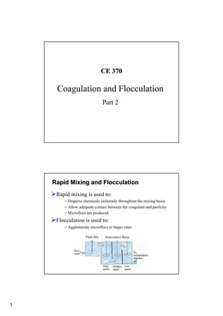
- 1. 1 CE 370 CE 370 Coagulation and Flocculation Part 2 Rapid Mixing and Flocculation Rapid Mixing and Flocculation ¾Rapid mixing is used to: −Disperse chemicals uniformly throughout the mixing basin −Allow adequate contact between the coagulant and particles −Microflocs are produced ¾Flocculation is used to: −Agglomerate microflocs to larger ones
- 2. 2 Devices Devices ¾Agitation in rapid mixing and flocculation is performed by: −Mechanical agitators (most common) −Pneumatic agitators −Baffled basins Design Design ¾The degree of mixing is based on the power provided, which is measured by the velocity gradient: − G = velocity gradient, sec-1 − W = power imparted per unit volume of basin, N-m/s-m3 − P = power imparted, N-m/s − V = basin volume, m3 − µ = absolute viscosity of water ( µ=0.00131 N-s/m2) V P W G µ µ = =
- 3. 3 Velocity Gradient Velocity Gradient ¾The velocity gradient of two fluid particles that are 0.05ft apart with a relative velocity of 0.2fps is equal to: 2fps/0.05ft = 40fps/ft 2fps/0.05ft = 40fps/ft Design Design ¾The velocity gradient for baffle basins is: − γ = specific weight of water − hL = head loss due to friction and turbulence − T = detention time T h G L µ γ =
- 4. 4 Velocity Gradient Velocity Gradient ¾The rate of particle collision ∝ G ¾Shear force ∝ G ¾Total number of particle collisions ∝ GT Rapid Mixing Rapid Mixing ¾Mixing devices ¾Detention time ¾Types of impellers
- 5. 5 Mixing Devices Mixing Devices Mixing Devices Mixing Devices
- 6. 6 Mixing Devices Mixing Devices Detention Time Detention Time 700 50 790 40 900 30 1000 20 G (fps/f or sec-1; mps/m of s-1) T (Seconds) Typical detention times and velocity gradients for rapid mixing basins are given in the table below:
- 7. 7 Rotary Mixing Rotary Mixing ¾Rotary mixing devices can be −Turbines −Paddle impellers −propellers Turbine Impellers Turbine Impellers
- 8. 8 Paddle Impeller Paddle Impeller Propeller Impeller Propeller Impeller
- 9. 9 Impeller Design Impeller Design The power imparted to the liquid by various impellers is given by: For turbulent flow (NRe > 10,000) in a baffled tank: P = KT n3 D5 i ρ Where: P = power, ft-lb/sec (N-m/s) KT = impeller constant for turbulent flow n = rotational speed, rps Di = impeller diameter, ft (m) ρ = density of the liquid, ρ = γ/g γ = specific weight of the liquid, lb/ft3 g = gravity, 32.17 ft/sec2 (9.81 m/s2) For unbaffled tanks the power imparted is 75% of the baffled tanks Impeller Design Impeller Design For laminar flow (NRe < 10 to 20) in a baffled or unbaffled tank: P = KL n2 D3 i µ Where: P = power, ft-lb/sec (N-m/s) KL = impeller constant for laminar flow flow n = rotational speed, rps Di = impeller diameter, ft (m) µ = absolute viscosity, lb-force-sec/ft2 (N-s/m2) Reynolds number for impellers is given by: NRe = D2 i n ρ / µ Table 8.2 gives values for KT and KL for baffled tanks
- 10. 10 Example Example – – Rapid Mixing Rapid Mixing A square rapid-mixing basin, with a depth of water equal to 1.25 times the width, is to be designed for a flow of 7570 m3/d. The velocity gradient is to be 790 mps/m, the detention time is 40 seconds, the operating temperature is 10° C, and the turbine shaft speed is 100 rpm. Determine: •The basin dimensions •The power required Solution Solution Find the volume of the basin, V = Q / t The dimensions are (W)(W)(1.25W) = 3.50 m3 W = 1.41 m The depth of the basin, H = (1.25)(1.41 m) = 1.76 m Use W = 1.41 m; H = 1.76 Using the velocity gradient equation 3 3 5 . 3 sec 40 sec 60 min min 1440 7570 m m V = × × = s m N m m s N V G P / 2863 ) 5 . 3 ( sec) / 790 )( / 0013 . 0 ( 3 2 2 2 − = − = = µ W 1.25 W W W
- 11. 11 Flocculation Flocculation ¾Agitation is provided by: −Mechanical agitation (most common) OR −Pneumatic agitation ¾Mechanical agitation is provided using: −Paddle wheels (most common) −Turbines −Propellers
- 12. 12 ¾Complete flocculation depends on: − The relative ease and rate of by which the small microfloc aggregate into large floc particles − Number of particle collisions ¾OR in other words, it depends on: − Floc characteristics − G (if G is too high, large floc will not be formed) − GT (gives indication on the number of collisions) ¾Fragile flocs require low G values (<5/sec) ¾High-strength flocs require high G values (≈10/sec) Flocculation Flocculation
- 13. 13 Flocculation Basins Flocculation Basins ¾Designed to provide tapered flocculation [decreasing G values (high 50 to low 20 to lower 10/sec)] ¾Horizontal and vertical shafts are used to mount the paddle wheel ¾Flocculation basins are composed of minimum 3 compartments to: −Minimize short circuiting −Facilitate tapered flocculation High G Low G Lower G
- 14. 14 Flocculation Basins Flocculation Basins ¾For cross-flow, tapered flocculation can be provided by: − − Varying the paddle size Varying the paddle size − − Varying the number of paddles Varying the number of paddles − − Varying the diameter of the paddle wheels Varying the diameter of the paddle wheels − − Varying the rotational speed of the various shafts Varying the rotational speed of the various shafts ¾For axial-flow, tapered flocculation can be provided by: − − Varying the paddle size Varying the paddle size − − Varying the number of paddles Varying the number of paddles
- 15. 15 Paddle Wheels Design Paddle Wheels Design The power imparted by paddle wheels is given by the following: Where: CD = Coefficient of drag A = Paddle area, ft2 (m2) ρ = density of the liquid, ρ = γ/g v = Velocity of the paddle relative to water, fps (mps) g = gravity, 32.17 ft/sec2 (9.81 m/s2) Table 8.3 gives values for drag coefficient. 2 2 3 3 v g A C v A C P D D γ ρ = =
- 16. 16 Example on Flocculation Example on Flocculation A cross-flow, horizontal shaft, paddle wheel flocculation basin is to be designed for a flow of 25,000m3/d, a mean velocity gradient of 26.7/sec (at 10° C), and a detention time of 45 minutes. The GT value should be from 50,000 to 100,000. Tapered flocculation is to be provided, and the three compartments of equal depth in series are to be used. The G values determined from laboratory tests for the three compartments are G1 = 50/sec, G2 = 20/sec, and G3 = 10/sec. These give an average G value of 26.7/sec. The compartments are to be separated by slotted, redwood baffle fences, and the floor of the basin is level. The basin should be 1.5 m in width to adjoin the settling tank. Determine: 1. The GT value 2. The basin dimensions 3. The power to be imparted to the water in each compartment Example on Flocculation Example on Flocculation Solution The GT value = (26.7/sec)(45 min)(60 sec/min) = 72,100 Since GT value is between 50,000 and 100,000, the detention time is satisfactory. Basin volume, V = (flow) × (detention time) = (25,000 m3/d)(45 min)(hr/60 min) = 781 m3 Profile area = (volume / width) = (781 m3 / 15 m) = 52.1 m2 Assume compartments are square in profile, and x is the compartment width and depth. Thus, (3x)(x) = 52.1 x2 = 17.37x = 4.17 m 3x = 3(4.17) = 12.51m Then, width = depth = 4.17 m length = 12.51 m volume = (4.17)(12.51)(15.0) = 783 m3 The Power, P = µG2V (at 10° C, µ = 0.00131 N-s/m2) P (for first compartment) = (0.00131 N-s/m2)(502/s2)(783 m3/3) = 855 N-m/s = 855 J/s = 855 W P (for second compartment) = (0.00131)(202)(783/3) = 137 W P (for third compartment) = (0.00131)(102)(783/3) = 34.2 W
- 17. 17 Coagulation & Flocculation in Coagulation & Flocculation in Wastewater Treatment Wastewater Treatment ¾The same aluminum and iron salts are used in wastewater ¾Wastewater requires higher dosages (≥ 300 mg/l) and coagulates faster than surface water ¾Beside coagulation, lime and iron salts remove phosphorous ¾Coagulant aids include polyelectrolytes, addition of turbidity and lime addition Coagulation & Flocculation in Coagulation & Flocculation in Wastewater Treatment Wastewater Treatment ¾Rapid-mixing basins have detention time of 1 to 2 minutes (due to high SS and large coagulant dosage) ¾Velocity gradients in rapid-mixing basins are about 300/sec, which are lower than those for water (due to nature of organic solid) ¾GT and T are lower than those used with water
- 18. 18 Coagulation & Flocculation in Coagulation & Flocculation in Wastewater Treatment Wastewater Treatment ¾For alum and iron salts − − T is typically 15 to 30 min T is typically 15 to 30 min − − G is typically 20 to 75/sec G is typically 20 to 75/sec − − GT is typically 10,000 to 100,000 GT is typically 10,000 to 100,000 ¾For lime − − T is typically 1 to 2 min in rapid T is typically 1 to 2 min in rapid- -mixing basins mixing basins − − T is typically 5 to 10 min in flocculation basins T is typically 5 to 10 min in flocculation basins − − G is typically G is typically ≥ ≥ 100/sec 100/sec