SlideShare a Scribd company logo
1 of 16
Download to read offline
2009 ACCESSORIES & BODY, CAB
Instrument Panel and Console - Flex
SPECIFICATIONS
TORQUE SPECIFICATIONS
DESCRIPTION AND OPERATION
REFRIGERATOR
The rear floor console may be equipped with a refrigerator feature. The refrigerator operates only when the
ignition is in the ON position. The refrigerator should only be used when the engine is running. If there is a
need to use the unit when the engine is off, limit the time the refrigerator is running to avoid draining the
battery.
If the refrigerator is active and the ignition is turned to the OFF position, the refrigerator will also turn off. The
last known state of the refrigerator will be stored into the refrigerator module memory. When the ignition is
turned back to the ON position, the refrigerator/freezer will automatically activate to the last known state that is
stored in the refrigerator module memory.
The refrigerator/freezer is equipped with the following:
 Refrigerator switch (located on rear floor console)
 Compressor/motor assembly (not serviceable)
 Refrigerant (not serviceable)
 Refrigerator module (not serviceable)
Description Nm lb-ft lb-in
Front floor console lower bolts 6 - 53
Front floor console rear lower bolts 6 - 53
Ground wire bolts 10 - 89
Instrument panel center support bracket bolts 25 18 -
Instrument panel side bolts 40 30 -
Instrument panel upper cowl bolts 25 18 -
PCM nuts 5 - 44
Passenger side air bag-to-cross beam bolts 9 - 80
Rear floor console bolts 7 - 62
Steering column shaft-to-steering column bolt 25 18 -
Strut upper mount nuts 30 22 -
Thermostatic Expansion Valve (TXV) manifold bolt 8 - 71
2009 Ford Flex SE
2009 ACCESSORIES & BODY, CAB Instrument Panel and Console - Flex
2009 Ford Flex SE
2009 ACCESSORIES & BODY, CAB Instrument Panel and Console - Flex
Microsoft
Thursday, April 22, 2010 8:42:11 AM Page 1 © 2006 Mitchell Repair Information Company, LLC.
Microsoft
Thursday, April 22, 2010 8:42:16 AM Page 1 © 2006 Mitchell Repair Information Company, LLC.
Cool Mode
To activate the refrigerator, depress the refrigerator switch to the COOL position for approximately 1 second
until the COOL LED illuminates. When the refrigerator is in cool mode, the temperature will cool to
approximately 41°F (5°C). In order to turn the refrigerator off when the refrigerator is in cool mode, depress the
refrigerator switch to the COOL position for approximately 1 second, until the COOL LED turns off. When the
refrigerator is in the cool mode, the refrigerator can be switched to freeze mode by depressing the refrigerator
switch to the FREEZE position for approximately 1 second, until the COOL LED turns off and the FREEZE
LED illuminates.
Freeze Mode
To activate the freezer, depress the refrigerator switch to the FREEZE position for approximately 1 second,
until the FREEZE LED illuminates. When the refrigerator is in freeze mode, the temperature will cool to
approximately 23°F (-5°C). In order to turn the freezer off when the refrigerator is in freezer mode, depress the
refrigerator switch to the FREEZE position for approximately 1 second, until the FREEZE LED turns off. When
the refrigerator is in the freeze mode, the refrigerator can be switched to cool mode by depressing the
refrigerator switch to the COOL position for approximately 1 second, until the FREEZE LED turns off and the
COOL LED illuminates.
Diagnostic Mode
In the event of a system concern, the refrigerator is equipped with the capabilities to provide self diagnostics.
For information on the diagnostic mode, refer to the Principles of Operation located in REFRIGERATOR.
DIAGNOSIS AND TESTING
REFRIGERATOR
Special Tool(s)
SPECIAL TOOL REFERENCE CHART
73III Automotive Meter
105-R0057 or equivalent
2009 Ford Flex SE
2009 ACCESSORIES & BODY, CAB Instrument Panel and Console - Flex
Microsoft
Thursday, April 22, 2010 8:42:11 AM Page 2 © 2006 Mitchell Repair Information Company, LLC.
Principles of Operation
Refrigerator
The refrigerator consists of a switch, module and motor assembly, which contains a cooling fan, refrigerant, a
condenser and a compressor. The refrigerator relay, located in the Battery Junction Box (BJB), controls voltage
to the refrigerator. The refrigerator relay coil is grounded at all times. When the ignition switch is in the RUN or
ACCESSORY position, voltage is supplied to the refrigerator relay coil from Smart Junction Box (SJB) fuse 34
(5A) and the relay closes. When the refrigerator relay is closed, voltage is sent to the refrigerator from BJB fuse
15 (15A).
The temperature of the refrigerator is controlled by a sensor located in the refrigerator module. When a
refrigerator mode is selected and the refrigerator temperature is above the target temperature, the compressor
will activate. If the temperature is below the target temperature, there is no need for cooling and the compressor
will stop. The compressor start up has a predetermined time delay to avoid a potential rapid changing
compressor on and off situation.
The heat from the compressor and condenser is pushed out of the vents of the refrigerator by means of a fan.
This fan runs continuously, as soon as a refrigerator mode is selected. The fan will not stop with the compressor
if the target temperature is reached.
Diagnostic Mode
The refrigerator can be switched into a diagnostic mode to read the potential error codes of the compressor.
When the refrigerator is in diagnostic mode, the COOL LED on the refrigerator switch will flash 1-5 times,
2009 Ford Flex SE
2009 ACCESSORIES & BODY, CAB Instrument Panel and Console - Flex
Microsoft
Thursday, April 22, 2010 8:42:11 AM Page 3 © 2006 Mitchell Repair Information Company, LLC.
depending on the error. Perform the following steps in order to access the refrigerator diagnostic mode:
1. Turn the ignition switch to the ON position.
2. Depress the refrigerator switch to the FREEZE position for approximately 1 second, until the FREEZE
LED illuminates.
3. Depress the refrigerator switch again to the FREEZE position for approximately 5 seconds, until the
FREEZE LED flashes quickly and repeatedly.
4.
When the FREEZE LED is quickly flashing, the COOL LED will display the error code by flashing 1-5
times, depending on the error.
5.
To turn the diagnostic mode off, depress the refrigerator switch to the FREEZE position for approximately 1
second. The FREEZE LED will stop flashing, but it will remain illuminated and the refrigerator will be in
freeze mode.
DIAGNOSTIC ERROR CODE DESCRIPTION CHART
Inspection and Verification
1. Verify the customer concern.
NOTE: Use the Diagnostic Mode Error Code Chart to determine the error.
NOTE: If the refrigerator is in diagnostic mode and the ignition is turned OFF, the
refrigerator will restart in FREEZE mode when the ignition is turned back
to the ON position.
Number
of Flashes
Diagnostic
Error Code
Diagnostic Error Code Description
1
Battery
protection
cutout
The voltage level at the refrigerator 12 volt connector is below the parameter
settings. This code may set when the refrigerator has been active with the
engine off.
2
Fan over-
current cut-out
The fan loads the electronic unit with more than 1 amp peak. Refer to
INSPECTION AND VERIFICATION.
3
Motor start
error
The rotor is blocked or the differential pressure in the unit is too high. This
may occur in high ambient temperature situations or if the refrigerator was
stopped and restarted within a short period at a high load and/or a high
ambient temperature condition. Let the differential pressure lower, before
attempting to restart the refrigerator.
4
Minimum
motor speed
error
The refrigeration system is so heavily loaded by ambient temperatures that the
motor cannot maintain a minimum speed of 1,850 rpm. Let the refrigerator
system cool down before attempting to restart the refrigerator.
5
Thermal cut-
out of
electrical unit
The refrigerator is so heavily loaded by ambient temperatures that the
refrigerator module gets too hot. Check the vents and the area of the
compressor, condenser for a blockage, possibly from dust. Check the fan for
correct operation.
2009 Ford Flex SE
2009 ACCESSORIES & BODY, CAB Instrument Panel and Console - Flex
Microsoft
Thursday, April 22, 2010 8:42:11 AM Page 4 © 2006 Mitchell Repair Information Company, LLC.
2. Visually inspect for obvious signs of mechanical or electrical damage:
VISUAL INSPECTION CHART
3. If an obvious cause for an observed or reported concern is found, correct the cause (if possible) before
proceeding to the next step.
4. If the concern is not visually evident, verify the symptom and GO to SYMPTOM CHART.
Symptom Chart
SYMPTOM CHART
Pinpoint Tests
Pinpoint Test A: The Refrigerator Does Not Operate Correctly
Refer to SYSTEM WIRING DIAGRAMS , Refrigerated Console for schematic and connector information.
Normal Operation
When the ignition switch is in the RUN or ACCESSORY position, voltage is supplied to the refrigerator relay
coil from Smart Junction Box (SJB) fuse 34 (5A), through circuit CBP34 (VT/BN). The refrigerator relay coil is
grounded at all times through circuit GD120 (BK/GN). High current voltage is supplied to the refrigerator relay
from Battery Junction Box (BJB) fuse 15 (15A), through circuit SBB15 (WH/RD). When the refrigerator relay
is activated, voltage is supplied to the refrigerator through circuit CBB15 (BN/BU). The refrigerator is
grounded through circuit GD149 (BK/GY).
This pinpoint test is intended to diagnose the following:
Mechanical Electrical
 Refrigerator
 Battery Junction Box (BJB) fuse 15 (15A)
 Smart Junction Box (SJB) fuse 34 (5A)
 Refrigerator
 Refrigerator relay
 Refrigerator switch
 Loose or corroded connections
 Wiring harness
Condition Possible Sources Action
 The refrigerator does not operate
correctly
 Fuse(s)
 Refrigerator relay
 Refrigerator
switch
 Refrigerator
 Circuitry
 Go To PINPOINT TEST
A.
2009 Ford Flex SE
2009 ACCESSORIES & BODY, CAB Instrument Panel and Console - Flex
Microsoft
Thursday, April 22, 2010 8:42:11 AM Page 5 © 2006 Mitchell Repair Information Company, LLC.
 Fuse(s)
 Refrigerator relay
 Refrigerator switch
 Refrigerator
 Wiring, terminals or connectors
PINPOINT TEST A: THE REFRIGERATOR DOES NOT OPERATE CORRECTLY
A1 CHECK CIRCUIT CBB15 (BN/BU) FOR VOLTAGE
 Disconnect: Refrigerator C3415.
 Ignition ON.
 Measure the voltage between refrigerator C3415-1, circuit CBB15 (BN/BU), harness side and
ground.
Fig. 1: Measuring Voltage Between Refrigerator C3415-1, Circuit CBB15 (BN/BU), Harness
Side And Ground
Courtesy of FORD MOTOR CO.
 Is the voltage greater than 10 volts?
Yes : GO to A6.
No : GO to A2.
A2 CHECK THE REFRIGERATOR RELAY
 Ignition OFF.
 Disconnect: Refrigerator Relay.
 Carry out the Relay component test for the BJB refrigerator relay.
Refer to SYSTEM WIRING DIAGRAMS for component testing.
 Did the refrigerator relay pass the component test?
Yes : GO to A3.
No : INSTALL a new refrigerator relay. TEST the system for normal operation.
A3 CHECK CIRCUIT CBP34 (VT/BN) FOR VOLTAGE
 Ignition ON.
2009 Ford Flex SE
2009 ACCESSORIES & BODY, CAB Instrument Panel and Console - Flex
Microsoft
Thursday, April 22, 2010 8:42:11 AM Page 6 © 2006 Mitchell Repair Information Company, LLC.
 Measure the voltage between BJB refrigerator relay pin 1, circuit CBP34 (VT/BN), harness side
and ground.
Fig. 2: Measuring Voltage Between BJB Refrigerator Relay Pin 1, Circuit CBP34 (VT/BN),
Harness Side And Ground
Courtesy of FORD MOTOR CO.
 Is the voltage greater than 10 volts?
Yes : GO to A4.
No : VERIFY SJB fuse 34 (5A) is OK. If OK, REPAIR the circuit. If not OK, REFER to the
appropriate SystemWiring Diagrams to identify the possible causes of the circuit short. TEST the
system for normal operation.
A4 CHECK CIRCUIT SBB15 (WH/RD) FOR VOLTAGE
 Measure the voltage between BJB refrigerator relay pin 3, circuit SBB15 (WH/RD), harness side
and ground.
2009 Ford Flex SE
2009 ACCESSORIES & BODY, CAB Instrument Panel and Console - Flex
Microsoft
Thursday, April 22, 2010 8:42:11 AM Page 7 © 2006 Mitchell Repair Information Company, LLC.
Fig. 3: Measuring Voltage Between BJB Refrigerator Relay Pin 3, Circuit SBB15 (WH/RD),
Harness Side And Ground
Courtesy of FORD MOTOR CO.
 Is the voltage greater than 10 volts?
Yes : GO to A5.
No : VERIFY BJB fuse 15 (15A) is OK. If OK, REPAIR the circuit. If not OK, REFER to the
appropriate System Wiring Diagrams to identify the possible causes of the circuit short. TEST the
system for normal operation.
A5 CHECK FRONT WIPER RELAY CIRCUIT GD120 (BK/GN) FOR GROUND
 Measure the resistance between BJB refrigerator relay pin 2, circuit GD120 (BK/GN) and ground.
2009 Ford Flex SE
2009 ACCESSORIES & BODY, CAB Instrument Panel and Console - Flex
Microsoft
Thursday, April 22, 2010 8:42:11 AM Page 8 © 2006 Mitchell Repair Information Company, LLC.
Fig. 4: Measuring Resistance Between BJB Refrigerator Relay Pin 2, Circuit GD120 (BK/GN)
And Ground
Courtesy of FORD MOTOR CO.
 Is the resistance less than 5 ohms?
Yes : REPAIR open in circuit CBB15 (BN/BU). TEST the system for normal operation.
No : REPAIR open in circuit GD120 (BK/GN). TEST the system for normal operation.
A6 CHECK CIRCUIT GD149 (BK/GY) FOR AN OPEN
 Ignition OFF.
 Measure the resistance between refrigerator C3415-3, circuit GD149 (BK/GY), harness side and
ground.
Fig. 5: Measuring Resistance Between Refrigerator C3415-3, Circuit GD149 (BK/GY),
Harness Side And Ground
Courtesy of FORD MOTOR CO.
2009 Ford Flex SE
2009 ACCESSORIES & BODY, CAB Instrument Panel and Console - Flex
Microsoft
Thursday, April 22, 2010 8:42:11 AM Page 9 © 2006 Mitchell Repair Information Company, LLC.
 Is the resistance less than 5 ohms?
Yes : GO to A7.
No : REPAIR the circuit(s). TEST the system for normal operation.
A7 CHECK THE REFRIGERATOR SWITCH
 Remove the refrigerator switch. Refer to REFRIGERATOR SWITCH.
 Carry out the Refrigerator Switch Component Test.
 Did the refrigerator switch pass the component test?
Yes : GO to A8.
No : INSTALL a new refrigerator switch.
A8 CHECK FOR CORRECT REFRIGERATOR OPERATION
 Disconnect all refrigerator connectors.
 Check for:
 corrosion.
 pushed-out pins.
 Connect all the refrigerator connectors and make sure they seat correctly.
 Operate the system and verify the concern is still present.
 Is the concern still present?
Yes : INSTALL a new refrigerated rear floor console. REFER to CONSOLE - REAR, FLOOR.
No : The system is operating correctly at this time. Concern may have been caused by a loose or
corroded connector. TEST the system for normal operation.
Component Test
Refrigerator Switch
Fig. 6: Identifying Refrigerator Switch
Courtesy of FORD MOTOR CO.
REFRIGERATOR SWITCH REFERENCE CHART
Connect Self-Powered Test Light or Ohmmeter to
Terminals
Move Switch to this
Position
A Good Switch will
Indicate
1 and 2 COOL Closed
2009 Ford Flex SE
2009 ACCESSORIES & BODY, CAB Instrument Panel and Console - Flex
Microsoft
Thursday, April 22, 2010 8:42:11 AM Page 10 © 2006 Mitchell Repair Information Company, LLC.
REMOVAL AND INSTALLATION
INSTRUMENT PANEL - EXPLODED VIEW
Instrument Panel Finish Panels and Fasteners
1 and 3 - Open
1 and 4 - Open
1 and 5 - Open
1 and 6 FREEZE Closed
2 and 3 - Open
2 and 4 - Open
2 and 5 - Open
2 and 6 - Open
3 and 4 - Open
3 and 5 - Open
3 and 6 - Open
4 and 5 - Open
4 and 6 - Open
5 and 6 - Open
2009 Ford Flex SE
2009 ACCESSORIES & BODY, CAB Instrument Panel and Console - Flex
Microsoft
Thursday, April 22, 2010 8:42:11 AM Page 11 © 2006 Mitchell Repair Information Company, LLC.
Thank you very much for
your reading. Please Click
Here. Then Get COMPLETE
MANUAL. NO WAITING
NOTE:
If there is no response to
click on the link above,
please download the PDF
document first and then
click on it.
Fig. 7: Exploded View Of Instrument Panel With Torque Specifications
Courtesy of FORD MOTOR CO.
WINDOW MOULDING - REAR QUARTER
Instrument Panel Trim Panels, Finish Panels and Electrical Connectors
Item Part Number Description
1 W709178 Instrument panel upper cowl bolt (3 required)
2 04480 RH/ 04481 LH Instrument panel side trim panel
3 W712210 Instrument panel side finish panel retaining clip (5 required per side)
4 W712961 Steering column shaft-to-steering column bolt
5 W710259 Instrument panel side bolt (6 required)
6 W709268 Instrument panel center support bracket bolt (4 required)
2009 Ford Flex SE
2009 ACCESSORIES & BODY, CAB Instrument Panel and Console - Flex
Microsoft
Thursday, April 22, 2010 8:42:11 AM Page 12 © 2006 Mitchell Repair Information Company, LLC.
Fig. 8: Identifying Instrument Panel Trim Panels, Finish Panels And Electrical Connectors
Courtesy of FORD MOTOR CO.
WINDOW MOULDING - REAR QUARTER
Item Part Number Description
1 N808453 Steering column opening trim panel screw (3 required)
2 04459 Steering column opening trim panel
3 W712210 Steering column opening trim panel retaining clip (3 required)
4 - LH instrument panel electrical connector (part of 14401)
5 - Lower LH instrument panel electrical connectors (part of 14401)
6 - Small RCM electrical connector (part of 14401)
7 - RH instrument panel electrical connector (part of 14401)
8 18812A Antenna cable
9 04338 RH Instrument panel finish panel
2009 Ford Flex SE
2009 ACCESSORIES & BODY, CAB Instrument Panel and Console - Flex
Microsoft
Thursday, April 22, 2010 8:42:11 AM Page 13 © 2006 Mitchell Repair Information Company, LLC.
Instrument Panel and Instrument Cluster Finish Panels
Fig. 9: Identifying Instrument Panel And Instrument Cluster Finish Panels
Courtesy of FORD MOTOR CO.
REMOVAL AND INSTALLATION
Instrument Panel Upper Section
10 W712210 RH Instrument panel finish panel retaining clip (8 required)
11 04339 LH Instrument panel finish panel
12 W712210 LH Instrument panel finish panel retaining clip (2 required)
Item Part Number Description
1 W707628 Center instrument panel finish panel screw (6 required)
2 04302 Center instrument panel finish panel
3 W712210 Center instrument panel finish panel retaining clip (7 required)
4 - Instrument cluster finish panel screw covers (part of 044D70)
5 W707628 Instrument cluster finish panel screw (3 required)
6 044D70 Instrument cluster finish panel
7 W712210 Instrument cluster finish panel retaining clip (3 required)
8 13A018 Light sensor
9 - Light sensor electrical connector (part of 14401)
10 044E82 Instrument panel defroster grille
11 W712210 Instrument panel defroster grille retaining clip (14 required)
2009 Ford Flex SE
2009 ACCESSORIES & BODY, CAB Instrument Panel and Console - Flex
Microsoft
Thursday, April 22, 2010 8:42:11 AM Page 14 © 2006 Mitchell Repair Information Company, LLC.
Fig. 10: Identifying Instrument Panel Upper Section
Courtesy of FORD MOTOR CO.
TIGHTENING TORQUE SPECIFICATIONS
1. For additional information, refer to the appropriate procedures.
INSTRUMENT PANEL
Removal
1. Rotate the steering wheel until the front wheels are in the straight-ahead position.
2. Drain the coolant. For additional information, refer to ENGINE COOLING .
3. Recover the refrigerant. For additional information, refer to CLIMATE CONTROL SYSTEM -
GENERAL INFORMATION AND DIAGNOSTICS .
4. Remove the wiper mounting arm and pivot shaft assembly. For additional information, refer to WIPERS
AND WASHERS .
5. Disconnect the 3 PCM electrical connectors.
Item Part Number Description
1 W505424 Hood release handle bolt
2 16916 Hood release handle
3 W707628 Instrument panel upper section screw (13 required)
4 04320 Instrument panel upper section
5 04545 In-vehicle crossbeam
2009 Ford Flex SE
2009 ACCESSORIES & BODY, CAB Instrument Panel and Console - Flex
Microsoft
Thursday, April 22, 2010 8:42:11 AM Page 15 © 2006 Mitchell Repair Information Company, LLC.

More Related Content

Similar to 2011 FORD FLEX Service Repair Manual.pdf

Service training top therm chiller 1 6 k w-eng_01.10.2014
Service training top therm chiller 1 6 k w-eng_01.10.2014Service training top therm chiller 1 6 k w-eng_01.10.2014
Service training top therm chiller 1 6 k w-eng_01.10.2014Nickna16
 
Manual reparacion Jeep Compass - Patriot Limited 2007-2009_Cooling
Manual reparacion Jeep Compass - Patriot Limited 2007-2009_CoolingManual reparacion Jeep Compass - Patriot Limited 2007-2009_Cooling
Manual reparacion Jeep Compass - Patriot Limited 2007-2009_CoolingGustavo Castro
 
Master-Bilt Rack Installation Manual
Master-Bilt Rack Installation ManualMaster-Bilt Rack Installation Manual
Master-Bilt Rack Installation ManualRay Johnson
 
Dom icondens he-26c-manual
Dom icondens he-26c-manualDom icondens he-26c-manual
Dom icondens he-26c-manualLewisHunt
 
Anole Hot Runner Controller
Anole Hot Runner ControllerAnole Hot Runner Controller
Anole Hot Runner ControllerAnole Hot Runner
 
Controllers manual-controller carrier-owners-manual-of-kjr-12_b-1438306116
Controllers manual-controller carrier-owners-manual-of-kjr-12_b-1438306116Controllers manual-controller carrier-owners-manual-of-kjr-12_b-1438306116
Controllers manual-controller carrier-owners-manual-of-kjr-12_b-1438306116Albert Bylykbashi
 
Catalogo Air Cooled Scroll Chiller LG.pdf
Catalogo Air Cooled Scroll Chiller LG.pdfCatalogo Air Cooled Scroll Chiller LG.pdf
Catalogo Air Cooled Scroll Chiller LG.pdfKarenGrau3
 
Toyota FJ Cruiser Interior Features Baltimore, Maryland
Toyota FJ Cruiser Interior Features Baltimore, MarylandToyota FJ Cruiser Interior Features Baltimore, Maryland
Toyota FJ Cruiser Interior Features Baltimore, MarylandJerry's Toyota
 
Volvo L220D Wheel Loader Service Repair Manual Instant Download.pdf
Volvo L220D Wheel Loader Service Repair Manual Instant Download.pdfVolvo L220D Wheel Loader Service Repair Manual Instant Download.pdf
Volvo L220D Wheel Loader Service Repair Manual Instant Download.pdffapanhe306271
 
Volvo L220D Wheel Loader Service Repair Manual Instant Download.pdf
Volvo L220D Wheel Loader Service Repair Manual Instant Download.pdfVolvo L220D Wheel Loader Service Repair Manual Instant Download.pdf
Volvo L220D Wheel Loader Service Repair Manual Instant Download.pdffijsekkkdmdm3e
 
Volvo L220D Wheel Loader Service Repair Manual Instant Download.pdf
Volvo L220D Wheel Loader Service Repair Manual Instant Download.pdfVolvo L220D Wheel Loader Service Repair Manual Instant Download.pdf
Volvo L220D Wheel Loader Service Repair Manual Instant Download.pdftepu22753653
 
Volvo L220D Wheel Loader Service Repair Manual Instant Download.pdf
Volvo L220D Wheel Loader Service Repair Manual Instant Download.pdfVolvo L220D Wheel Loader Service Repair Manual Instant Download.pdf
Volvo L220D Wheel Loader Service Repair Manual Instant Download.pdff8iosedkdm3e
 
Walk in cooler & freezer cold room plant & refrigerated cold storage warehous...
Walk in cooler & freezer cold room plant & refrigerated cold storage warehous...Walk in cooler & freezer cold room plant & refrigerated cold storage warehous...
Walk in cooler & freezer cold room plant & refrigerated cold storage warehous...svfd1721
 
Ae1287 copeland discus-compressors-with-demand-cooling-system
Ae1287 copeland discus-compressors-with-demand-cooling-systemAe1287 copeland discus-compressors-with-demand-cooling-system
Ae1287 copeland discus-compressors-with-demand-cooling-systemhernan hernandez
 

Similar to 2011 FORD FLEX Service Repair Manual.pdf (20)

Service training top therm chiller 1 6 k w-eng_01.10.2014
Service training top therm chiller 1 6 k w-eng_01.10.2014Service training top therm chiller 1 6 k w-eng_01.10.2014
Service training top therm chiller 1 6 k w-eng_01.10.2014
 
Manual reparacion Jeep Compass - Patriot Limited 2007-2009_Cooling
Manual reparacion Jeep Compass - Patriot Limited 2007-2009_CoolingManual reparacion Jeep Compass - Patriot Limited 2007-2009_Cooling
Manual reparacion Jeep Compass - Patriot Limited 2007-2009_Cooling
 
Master-Bilt Rack Installation Manual
Master-Bilt Rack Installation ManualMaster-Bilt Rack Installation Manual
Master-Bilt Rack Installation Manual
 
Dom icondens he-26c-manual
Dom icondens he-26c-manualDom icondens he-26c-manual
Dom icondens he-26c-manual
 
Anole Hot Runner Controller
Anole Hot Runner ControllerAnole Hot Runner Controller
Anole Hot Runner Controller
 
Controllers manual-controller carrier-owners-manual-of-kjr-12_b-1438306116
Controllers manual-controller carrier-owners-manual-of-kjr-12_b-1438306116Controllers manual-controller carrier-owners-manual-of-kjr-12_b-1438306116
Controllers manual-controller carrier-owners-manual-of-kjr-12_b-1438306116
 
Mh8 fc um
Mh8 fc umMh8 fc um
Mh8 fc um
 
Termostato 24 v proporcional belimo ext-rcp-24
Termostato 24 v proporcional   belimo ext-rcp-24Termostato 24 v proporcional   belimo ext-rcp-24
Termostato 24 v proporcional belimo ext-rcp-24
 
Catalogo Air Cooled Scroll Chiller LG.pdf
Catalogo Air Cooled Scroll Chiller LG.pdfCatalogo Air Cooled Scroll Chiller LG.pdf
Catalogo Air Cooled Scroll Chiller LG.pdf
 
Toyota FJ Cruiser Interior Features Baltimore, Maryland
Toyota FJ Cruiser Interior Features Baltimore, MarylandToyota FJ Cruiser Interior Features Baltimore, Maryland
Toyota FJ Cruiser Interior Features Baltimore, Maryland
 
Volvo L220D Wheel Loader Service Repair Manual Instant Download.pdf
Volvo L220D Wheel Loader Service Repair Manual Instant Download.pdfVolvo L220D Wheel Loader Service Repair Manual Instant Download.pdf
Volvo L220D Wheel Loader Service Repair Manual Instant Download.pdf
 
Volvo L220D Wheel Loader Service Repair Manual Instant Download.pdf
Volvo L220D Wheel Loader Service Repair Manual Instant Download.pdfVolvo L220D Wheel Loader Service Repair Manual Instant Download.pdf
Volvo L220D Wheel Loader Service Repair Manual Instant Download.pdf
 
Volvo L220D Wheel Loader Service Repair Manual Instant Download.pdf
Volvo L220D Wheel Loader Service Repair Manual Instant Download.pdfVolvo L220D Wheel Loader Service Repair Manual Instant Download.pdf
Volvo L220D Wheel Loader Service Repair Manual Instant Download.pdf
 
Volvo L220D Wheel Loader Service Repair Manual Instant Download.pdf
Volvo L220D Wheel Loader Service Repair Manual Instant Download.pdfVolvo L220D Wheel Loader Service Repair Manual Instant Download.pdf
Volvo L220D Wheel Loader Service Repair Manual Instant Download.pdf
 
ES-BOX2 User Powerwall Manual-Genixgreen.pdf
ES-BOX2 User Powerwall Manual-Genixgreen.pdfES-BOX2 User Powerwall Manual-Genixgreen.pdf
ES-BOX2 User Powerwall Manual-Genixgreen.pdf
 
Pids
PidsPids
Pids
 
Walk in cooler & freezer cold room plant & refrigerated cold storage warehous...
Walk in cooler & freezer cold room plant & refrigerated cold storage warehous...Walk in cooler & freezer cold room plant & refrigerated cold storage warehous...
Walk in cooler & freezer cold room plant & refrigerated cold storage warehous...
 
Walk in cooler & freezer cold room plant & refrigerated cold storage warehous...
Walk in cooler & freezer cold room plant & refrigerated cold storage warehous...Walk in cooler & freezer cold room plant & refrigerated cold storage warehous...
Walk in cooler & freezer cold room plant & refrigerated cold storage warehous...
 
Ae1287 copeland discus-compressors-with-demand-cooling-system
Ae1287 copeland discus-compressors-with-demand-cooling-systemAe1287 copeland discus-compressors-with-demand-cooling-system
Ae1287 copeland discus-compressors-with-demand-cooling-system
 
Kalweka
KalwekaKalweka
Kalweka
 

More from zblun16398313

2011 INFINITI QX56 Service Repair Manual.pdf
2011 INFINITI QX56 Service Repair Manual.pdf2011 INFINITI QX56 Service Repair Manual.pdf
2011 INFINITI QX56 Service Repair Manual.pdfzblun16398313
 
2011 Infiniti G37 Coupe Service Repair Manual.pdf
2011 Infiniti G37 Coupe Service Repair Manual.pdf2011 Infiniti G37 Coupe Service Repair Manual.pdf
2011 Infiniti G37 Coupe Service Repair Manual.pdfzblun16398313
 
2011 Infiniti G37 Convertible Service Repair Manual.pdf
2011 Infiniti G37 Convertible Service Repair Manual.pdf2011 Infiniti G37 Convertible Service Repair Manual.pdf
2011 Infiniti G37 Convertible Service Repair Manual.pdfzblun16398313
 
2010 Toyota Corolla Service Repair Manual.pdf
2010 Toyota Corolla Service Repair Manual.pdf2010 Toyota Corolla Service Repair Manual.pdf
2010 Toyota Corolla Service Repair Manual.pdfzblun16398313
 
2010 Subaru Impreza Service Repair Manual.pdf
2010 Subaru Impreza Service Repair Manual.pdf2010 Subaru Impreza Service Repair Manual.pdf
2010 Subaru Impreza Service Repair Manual.pdfzblun16398313
 
2010 Nissan Rogue Service Repair Manual.pdf
2010 Nissan Rogue Service Repair Manual.pdf2010 Nissan Rogue Service Repair Manual.pdf
2010 Nissan Rogue Service Repair Manual.pdfzblun16398313
 
2010 Mitsubishi Lancer Service Repair Manual.pdf
2010 Mitsubishi Lancer Service Repair Manual.pdf2010 Mitsubishi Lancer Service Repair Manual.pdf
2010 Mitsubishi Lancer Service Repair Manual.pdfzblun16398313
 

More from zblun16398313 (7)

2011 INFINITI QX56 Service Repair Manual.pdf
2011 INFINITI QX56 Service Repair Manual.pdf2011 INFINITI QX56 Service Repair Manual.pdf
2011 INFINITI QX56 Service Repair Manual.pdf
 
2011 Infiniti G37 Coupe Service Repair Manual.pdf
2011 Infiniti G37 Coupe Service Repair Manual.pdf2011 Infiniti G37 Coupe Service Repair Manual.pdf
2011 Infiniti G37 Coupe Service Repair Manual.pdf
 
2011 Infiniti G37 Convertible Service Repair Manual.pdf
2011 Infiniti G37 Convertible Service Repair Manual.pdf2011 Infiniti G37 Convertible Service Repair Manual.pdf
2011 Infiniti G37 Convertible Service Repair Manual.pdf
 
2010 Toyota Corolla Service Repair Manual.pdf
2010 Toyota Corolla Service Repair Manual.pdf2010 Toyota Corolla Service Repair Manual.pdf
2010 Toyota Corolla Service Repair Manual.pdf
 
2010 Subaru Impreza Service Repair Manual.pdf
2010 Subaru Impreza Service Repair Manual.pdf2010 Subaru Impreza Service Repair Manual.pdf
2010 Subaru Impreza Service Repair Manual.pdf
 
2010 Nissan Rogue Service Repair Manual.pdf
2010 Nissan Rogue Service Repair Manual.pdf2010 Nissan Rogue Service Repair Manual.pdf
2010 Nissan Rogue Service Repair Manual.pdf
 
2010 Mitsubishi Lancer Service Repair Manual.pdf
2010 Mitsubishi Lancer Service Repair Manual.pdf2010 Mitsubishi Lancer Service Repair Manual.pdf
2010 Mitsubishi Lancer Service Repair Manual.pdf
 

Recently uploaded

一比一原版(Temple毕业证书)美国天普大学毕业证成绩单原件一模一样
一比一原版(Temple毕业证书)美国天普大学毕业证成绩单原件一模一样一比一原版(Temple毕业证书)美国天普大学毕业证成绩单原件一模一样
一比一原版(Temple毕业证书)美国天普大学毕业证成绩单原件一模一样fsdfdsgf
 
一比一定制加拿大新喀里多尼亚学院毕业证(UofL毕业证书)学位证书
一比一定制加拿大新喀里多尼亚学院毕业证(UofL毕业证书)学位证书一比一定制加拿大新喀里多尼亚学院毕业证(UofL毕业证书)学位证书
一比一定制加拿大新喀里多尼亚学院毕业证(UofL毕业证书)学位证书egfdgfd
 
Benefits of Load Planning in Fleet Management
Benefits of Load Planning in Fleet ManagementBenefits of Load Planning in Fleet Management
Benefits of Load Planning in Fleet Managementjennifermiller8137
 
一比一原版英国哈珀亚当斯大学毕业证如何办理
一比一原版英国哈珀亚当斯大学毕业证如何办理一比一原版英国哈珀亚当斯大学毕业证如何办理
一比一原版英国哈珀亚当斯大学毕业证如何办理AS
 
如何办理澳洲南澳大学毕业证(UniSA毕业证书)成绩单本科学位证原版一比一
如何办理澳洲南澳大学毕业证(UniSA毕业证书)成绩单本科学位证原版一比一如何办理澳洲南澳大学毕业证(UniSA毕业证书)成绩单本科学位证原版一比一
如何办理澳洲南澳大学毕业证(UniSA毕业证书)成绩单本科学位证原版一比一0uyfyq0q4
 
一比一原版(Auburn毕业证书)奥本大学毕业证原件一模一样
一比一原版(Auburn毕业证书)奥本大学毕业证原件一模一样一比一原版(Auburn毕业证书)奥本大学毕业证原件一模一样
一比一原版(Auburn毕业证书)奥本大学毕业证原件一模一样AS
 
原版定制英国格鲁斯特大学毕业证原件一模一样
原版定制英国格鲁斯特大学毕业证原件一模一样原版定制英国格鲁斯特大学毕业证原件一模一样
原版定制英国格鲁斯特大学毕业证原件一模一样AS
 
Toyota Yaris service manual Free.pdf Toyota Yaris Service manual
Toyota Yaris service manual Free.pdf  Toyota Yaris Service manualToyota Yaris service manual Free.pdf  Toyota Yaris Service manual
Toyota Yaris service manual Free.pdf Toyota Yaris Service manualAutocarmanuals.com
 
出售伯明翰大学毕业证研究生文凭证书原版质量
出售伯明翰大学毕业证研究生文凭证书原版质量出售伯明翰大学毕业证研究生文凭证书原版质量
出售伯明翰大学毕业证研究生文凭证书原版质量kthcah
 
Vina Score and Vin Min for almost all the models 2024
Vina Score and Vin Min for almost all the models 2024Vina Score and Vin Min for almost all the models 2024
Vina Score and Vin Min for almost all the models 2024jipohal318
 
Access to Rural Charging by David Skakel
Access to Rural Charging by David SkakelAccess to Rural Charging by David Skakel
Access to Rural Charging by David SkakelForth
 
Microscope of ppt for botany major this is a project
Microscope of ppt for botany major this is a projectMicroscope of ppt for botany major this is a project
Microscope of ppt for botany major this is a projectarpitakhairwar123
 
What Could Cause Your Audi To Keep Cutting Out
What Could Cause Your Audi To Keep Cutting OutWhat Could Cause Your Audi To Keep Cutting Out
What Could Cause Your Audi To Keep Cutting OutEuroautomotive
 
What Causes The BMW X7 Power Supply Warning To Illuminate
What Causes The BMW X7 Power Supply Warning To IlluminateWhat Causes The BMW X7 Power Supply Warning To Illuminate
What Causes The BMW X7 Power Supply Warning To IlluminateMedway Imports
 
Preparing for Transportation Electrification: The Electric Coop Perspective
Preparing for Transportation Electrification: The Electric Coop PerspectivePreparing for Transportation Electrification: The Electric Coop Perspective
Preparing for Transportation Electrification: The Electric Coop PerspectiveForth
 
Why Won't My Mercedes Key Fob Function After A Battery Swap
Why Won't My Mercedes Key Fob Function After A Battery SwapWhy Won't My Mercedes Key Fob Function After A Battery Swap
Why Won't My Mercedes Key Fob Function After A Battery SwapDreamcars Auto Repair
 
EV Charging Resources and Technical Assistance for Rural Communities and Trib...
EV Charging Resources and Technical Assistance for Rural Communities and Trib...EV Charging Resources and Technical Assistance for Rural Communities and Trib...
EV Charging Resources and Technical Assistance for Rural Communities and Trib...Forth
 
一比一原版(Cumbria毕业证书)英国坎布里亚大学毕业证成绩单学位证书
一比一原版(Cumbria毕业证书)英国坎布里亚大学毕业证成绩单学位证书一比一原版(Cumbria毕业证书)英国坎布里亚大学毕业证成绩单学位证书
一比一原版(Cumbria毕业证书)英国坎布里亚大学毕业证成绩单学位证书AD
 
What Might Be Behind Your Mercedes' Inoperative Cruise Control
What Might Be Behind Your Mercedes' Inoperative Cruise ControlWhat Might Be Behind Your Mercedes' Inoperative Cruise Control
What Might Be Behind Your Mercedes' Inoperative Cruise ControlM Service Inc
 

Recently uploaded (20)

一比一原版(Temple毕业证书)美国天普大学毕业证成绩单原件一模一样
一比一原版(Temple毕业证书)美国天普大学毕业证成绩单原件一模一样一比一原版(Temple毕业证书)美国天普大学毕业证成绩单原件一模一样
一比一原版(Temple毕业证书)美国天普大学毕业证成绩单原件一模一样
 
一比一定制加拿大新喀里多尼亚学院毕业证(UofL毕业证书)学位证书
一比一定制加拿大新喀里多尼亚学院毕业证(UofL毕业证书)学位证书一比一定制加拿大新喀里多尼亚学院毕业证(UofL毕业证书)学位证书
一比一定制加拿大新喀里多尼亚学院毕业证(UofL毕业证书)学位证书
 
Benefits of Load Planning in Fleet Management
Benefits of Load Planning in Fleet ManagementBenefits of Load Planning in Fleet Management
Benefits of Load Planning in Fleet Management
 
一比一原版英国哈珀亚当斯大学毕业证如何办理
一比一原版英国哈珀亚当斯大学毕业证如何办理一比一原版英国哈珀亚当斯大学毕业证如何办理
一比一原版英国哈珀亚当斯大学毕业证如何办理
 
如何办理澳洲南澳大学毕业证(UniSA毕业证书)成绩单本科学位证原版一比一
如何办理澳洲南澳大学毕业证(UniSA毕业证书)成绩单本科学位证原版一比一如何办理澳洲南澳大学毕业证(UniSA毕业证书)成绩单本科学位证原版一比一
如何办理澳洲南澳大学毕业证(UniSA毕业证书)成绩单本科学位证原版一比一
 
一比一原版(Auburn毕业证书)奥本大学毕业证原件一模一样
一比一原版(Auburn毕业证书)奥本大学毕业证原件一模一样一比一原版(Auburn毕业证书)奥本大学毕业证原件一模一样
一比一原版(Auburn毕业证书)奥本大学毕业证原件一模一样
 
原版定制英国格鲁斯特大学毕业证原件一模一样
原版定制英国格鲁斯特大学毕业证原件一模一样原版定制英国格鲁斯特大学毕业证原件一模一样
原版定制英国格鲁斯特大学毕业证原件一模一样
 
Toyota Yaris service manual Free.pdf Toyota Yaris Service manual
Toyota Yaris service manual Free.pdf  Toyota Yaris Service manualToyota Yaris service manual Free.pdf  Toyota Yaris Service manual
Toyota Yaris service manual Free.pdf Toyota Yaris Service manual
 
出售伯明翰大学毕业证研究生文凭证书原版质量
出售伯明翰大学毕业证研究生文凭证书原版质量出售伯明翰大学毕业证研究生文凭证书原版质量
出售伯明翰大学毕业证研究生文凭证书原版质量
 
Vina Score and Vin Min for almost all the models 2024
Vina Score and Vin Min for almost all the models 2024Vina Score and Vin Min for almost all the models 2024
Vina Score and Vin Min for almost all the models 2024
 
Access to Rural Charging by David Skakel
Access to Rural Charging by David SkakelAccess to Rural Charging by David Skakel
Access to Rural Charging by David Skakel
 
AI for Smart Vehicles - A quick overview
AI for Smart Vehicles - A quick overviewAI for Smart Vehicles - A quick overview
AI for Smart Vehicles - A quick overview
 
Microscope of ppt for botany major this is a project
Microscope of ppt for botany major this is a projectMicroscope of ppt for botany major this is a project
Microscope of ppt for botany major this is a project
 
What Could Cause Your Audi To Keep Cutting Out
What Could Cause Your Audi To Keep Cutting OutWhat Could Cause Your Audi To Keep Cutting Out
What Could Cause Your Audi To Keep Cutting Out
 
What Causes The BMW X7 Power Supply Warning To Illuminate
What Causes The BMW X7 Power Supply Warning To IlluminateWhat Causes The BMW X7 Power Supply Warning To Illuminate
What Causes The BMW X7 Power Supply Warning To Illuminate
 
Preparing for Transportation Electrification: The Electric Coop Perspective
Preparing for Transportation Electrification: The Electric Coop PerspectivePreparing for Transportation Electrification: The Electric Coop Perspective
Preparing for Transportation Electrification: The Electric Coop Perspective
 
Why Won't My Mercedes Key Fob Function After A Battery Swap
Why Won't My Mercedes Key Fob Function After A Battery SwapWhy Won't My Mercedes Key Fob Function After A Battery Swap
Why Won't My Mercedes Key Fob Function After A Battery Swap
 
EV Charging Resources and Technical Assistance for Rural Communities and Trib...
EV Charging Resources and Technical Assistance for Rural Communities and Trib...EV Charging Resources and Technical Assistance for Rural Communities and Trib...
EV Charging Resources and Technical Assistance for Rural Communities and Trib...
 
一比一原版(Cumbria毕业证书)英国坎布里亚大学毕业证成绩单学位证书
一比一原版(Cumbria毕业证书)英国坎布里亚大学毕业证成绩单学位证书一比一原版(Cumbria毕业证书)英国坎布里亚大学毕业证成绩单学位证书
一比一原版(Cumbria毕业证书)英国坎布里亚大学毕业证成绩单学位证书
 
What Might Be Behind Your Mercedes' Inoperative Cruise Control
What Might Be Behind Your Mercedes' Inoperative Cruise ControlWhat Might Be Behind Your Mercedes' Inoperative Cruise Control
What Might Be Behind Your Mercedes' Inoperative Cruise Control
 

2011 FORD FLEX Service Repair Manual.pdf

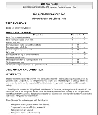
  • 1. 2009 ACCESSORIES & BODY, CAB Instrument Panel and Console - Flex SPECIFICATIONS TORQUE SPECIFICATIONS TORQUE SPECIFICATIONS DESCRIPTION AND OPERATION REFRIGERATOR The rear floor console may be equipped with a refrigerator feature. The refrigerator operates only when the ignition is in the ON position. The refrigerator should only be used when the engine is running. If there is a need to use the unit when the engine is off, limit the time the refrigerator is running to avoid draining the battery. If the refrigerator is active and the ignition is turned to the OFF position, the refrigerator will also turn off. The last known state of the refrigerator will be stored into the refrigerator module memory. When the ignition is turned back to the ON position, the refrigerator/freezer will automatically activate to the last known state that is stored in the refrigerator module memory. The refrigerator/freezer is equipped with the following:  Refrigerator switch (located on rear floor console)  Compressor/motor assembly (not serviceable)  Refrigerant (not serviceable)  Refrigerator module (not serviceable) Description Nm lb-ft lb-in Front floor console lower bolts 6 - 53 Front floor console rear lower bolts 6 - 53 Ground wire bolts 10 - 89 Instrument panel center support bracket bolts 25 18 - Instrument panel side bolts 40 30 - Instrument panel upper cowl bolts 25 18 - PCM nuts 5 - 44 Passenger side air bag-to-cross beam bolts 9 - 80 Rear floor console bolts 7 - 62 Steering column shaft-to-steering column bolt 25 18 - Strut upper mount nuts 30 22 - Thermostatic Expansion Valve (TXV) manifold bolt 8 - 71 2009 Ford Flex SE 2009 ACCESSORIES & BODY, CAB Instrument Panel and Console - Flex 2009 Ford Flex SE 2009 ACCESSORIES & BODY, CAB Instrument Panel and Console - Flex Microsoft Thursday, April 22, 2010 8:42:11 AM Page 1 © 2006 Mitchell Repair Information Company, LLC. Microsoft Thursday, April 22, 2010 8:42:16 AM Page 1 © 2006 Mitchell Repair Information Company, LLC.
  • 2. Cool Mode To activate the refrigerator, depress the refrigerator switch to the COOL position for approximately 1 second until the COOL LED illuminates. When the refrigerator is in cool mode, the temperature will cool to approximately 41°F (5°C). In order to turn the refrigerator off when the refrigerator is in cool mode, depress the refrigerator switch to the COOL position for approximately 1 second, until the COOL LED turns off. When the refrigerator is in the cool mode, the refrigerator can be switched to freeze mode by depressing the refrigerator switch to the FREEZE position for approximately 1 second, until the COOL LED turns off and the FREEZE LED illuminates. Freeze Mode To activate the freezer, depress the refrigerator switch to the FREEZE position for approximately 1 second, until the FREEZE LED illuminates. When the refrigerator is in freeze mode, the temperature will cool to approximately 23°F (-5°C). In order to turn the freezer off when the refrigerator is in freezer mode, depress the refrigerator switch to the FREEZE position for approximately 1 second, until the FREEZE LED turns off. When the refrigerator is in the freeze mode, the refrigerator can be switched to cool mode by depressing the refrigerator switch to the COOL position for approximately 1 second, until the FREEZE LED turns off and the COOL LED illuminates. Diagnostic Mode In the event of a system concern, the refrigerator is equipped with the capabilities to provide self diagnostics. For information on the diagnostic mode, refer to the Principles of Operation located in REFRIGERATOR. DIAGNOSIS AND TESTING REFRIGERATOR Special Tool(s) SPECIAL TOOL REFERENCE CHART 73III Automotive Meter 105-R0057 or equivalent 2009 Ford Flex SE 2009 ACCESSORIES & BODY, CAB Instrument Panel and Console - Flex Microsoft Thursday, April 22, 2010 8:42:11 AM Page 2 © 2006 Mitchell Repair Information Company, LLC.
  • 3. Principles of Operation Refrigerator The refrigerator consists of a switch, module and motor assembly, which contains a cooling fan, refrigerant, a condenser and a compressor. The refrigerator relay, located in the Battery Junction Box (BJB), controls voltage to the refrigerator. The refrigerator relay coil is grounded at all times. When the ignition switch is in the RUN or ACCESSORY position, voltage is supplied to the refrigerator relay coil from Smart Junction Box (SJB) fuse 34 (5A) and the relay closes. When the refrigerator relay is closed, voltage is sent to the refrigerator from BJB fuse 15 (15A). The temperature of the refrigerator is controlled by a sensor located in the refrigerator module. When a refrigerator mode is selected and the refrigerator temperature is above the target temperature, the compressor will activate. If the temperature is below the target temperature, there is no need for cooling and the compressor will stop. The compressor start up has a predetermined time delay to avoid a potential rapid changing compressor on and off situation. The heat from the compressor and condenser is pushed out of the vents of the refrigerator by means of a fan. This fan runs continuously, as soon as a refrigerator mode is selected. The fan will not stop with the compressor if the target temperature is reached. Diagnostic Mode The refrigerator can be switched into a diagnostic mode to read the potential error codes of the compressor. When the refrigerator is in diagnostic mode, the COOL LED on the refrigerator switch will flash 1-5 times, 2009 Ford Flex SE 2009 ACCESSORIES & BODY, CAB Instrument Panel and Console - Flex Microsoft Thursday, April 22, 2010 8:42:11 AM Page 3 © 2006 Mitchell Repair Information Company, LLC.
  • 4. depending on the error. Perform the following steps in order to access the refrigerator diagnostic mode: 1. Turn the ignition switch to the ON position. 2. Depress the refrigerator switch to the FREEZE position for approximately 1 second, until the FREEZE LED illuminates. 3. Depress the refrigerator switch again to the FREEZE position for approximately 5 seconds, until the FREEZE LED flashes quickly and repeatedly. 4. When the FREEZE LED is quickly flashing, the COOL LED will display the error code by flashing 1-5 times, depending on the error. 5. To turn the diagnostic mode off, depress the refrigerator switch to the FREEZE position for approximately 1 second. The FREEZE LED will stop flashing, but it will remain illuminated and the refrigerator will be in freeze mode. DIAGNOSTIC ERROR CODE DESCRIPTION CHART Inspection and Verification 1. Verify the customer concern. NOTE: Use the Diagnostic Mode Error Code Chart to determine the error. NOTE: If the refrigerator is in diagnostic mode and the ignition is turned OFF, the refrigerator will restart in FREEZE mode when the ignition is turned back to the ON position. Number of Flashes Diagnostic Error Code Diagnostic Error Code Description 1 Battery protection cutout The voltage level at the refrigerator 12 volt connector is below the parameter settings. This code may set when the refrigerator has been active with the engine off. 2 Fan over- current cut-out The fan loads the electronic unit with more than 1 amp peak. Refer to INSPECTION AND VERIFICATION. 3 Motor start error The rotor is blocked or the differential pressure in the unit is too high. This may occur in high ambient temperature situations or if the refrigerator was stopped and restarted within a short period at a high load and/or a high ambient temperature condition. Let the differential pressure lower, before attempting to restart the refrigerator. 4 Minimum motor speed error The refrigeration system is so heavily loaded by ambient temperatures that the motor cannot maintain a minimum speed of 1,850 rpm. Let the refrigerator system cool down before attempting to restart the refrigerator. 5 Thermal cut- out of electrical unit The refrigerator is so heavily loaded by ambient temperatures that the refrigerator module gets too hot. Check the vents and the area of the compressor, condenser for a blockage, possibly from dust. Check the fan for correct operation. 2009 Ford Flex SE 2009 ACCESSORIES & BODY, CAB Instrument Panel and Console - Flex Microsoft Thursday, April 22, 2010 8:42:11 AM Page 4 © 2006 Mitchell Repair Information Company, LLC.
  • 5. 2. Visually inspect for obvious signs of mechanical or electrical damage: VISUAL INSPECTION CHART 3. If an obvious cause for an observed or reported concern is found, correct the cause (if possible) before proceeding to the next step. 4. If the concern is not visually evident, verify the symptom and GO to SYMPTOM CHART. Symptom Chart SYMPTOM CHART Pinpoint Tests Pinpoint Test A: The Refrigerator Does Not Operate Correctly Refer to SYSTEM WIRING DIAGRAMS , Refrigerated Console for schematic and connector information. Normal Operation When the ignition switch is in the RUN or ACCESSORY position, voltage is supplied to the refrigerator relay coil from Smart Junction Box (SJB) fuse 34 (5A), through circuit CBP34 (VT/BN). The refrigerator relay coil is grounded at all times through circuit GD120 (BK/GN). High current voltage is supplied to the refrigerator relay from Battery Junction Box (BJB) fuse 15 (15A), through circuit SBB15 (WH/RD). When the refrigerator relay is activated, voltage is supplied to the refrigerator through circuit CBB15 (BN/BU). The refrigerator is grounded through circuit GD149 (BK/GY). This pinpoint test is intended to diagnose the following: Mechanical Electrical  Refrigerator  Battery Junction Box (BJB) fuse 15 (15A)  Smart Junction Box (SJB) fuse 34 (5A)  Refrigerator  Refrigerator relay  Refrigerator switch  Loose or corroded connections  Wiring harness Condition Possible Sources Action  The refrigerator does not operate correctly  Fuse(s)  Refrigerator relay  Refrigerator switch  Refrigerator  Circuitry  Go To PINPOINT TEST A. 2009 Ford Flex SE 2009 ACCESSORIES & BODY, CAB Instrument Panel and Console - Flex Microsoft Thursday, April 22, 2010 8:42:11 AM Page 5 © 2006 Mitchell Repair Information Company, LLC.
  • 6.  Fuse(s)  Refrigerator relay  Refrigerator switch  Refrigerator  Wiring, terminals or connectors PINPOINT TEST A: THE REFRIGERATOR DOES NOT OPERATE CORRECTLY A1 CHECK CIRCUIT CBB15 (BN/BU) FOR VOLTAGE  Disconnect: Refrigerator C3415.  Ignition ON.  Measure the voltage between refrigerator C3415-1, circuit CBB15 (BN/BU), harness side and ground. Fig. 1: Measuring Voltage Between Refrigerator C3415-1, Circuit CBB15 (BN/BU), Harness Side And Ground Courtesy of FORD MOTOR CO.  Is the voltage greater than 10 volts? Yes : GO to A6. No : GO to A2. A2 CHECK THE REFRIGERATOR RELAY  Ignition OFF.  Disconnect: Refrigerator Relay.  Carry out the Relay component test for the BJB refrigerator relay. Refer to SYSTEM WIRING DIAGRAMS for component testing.  Did the refrigerator relay pass the component test? Yes : GO to A3. No : INSTALL a new refrigerator relay. TEST the system for normal operation. A3 CHECK CIRCUIT CBP34 (VT/BN) FOR VOLTAGE  Ignition ON. 2009 Ford Flex SE 2009 ACCESSORIES & BODY, CAB Instrument Panel and Console - Flex Microsoft Thursday, April 22, 2010 8:42:11 AM Page 6 © 2006 Mitchell Repair Information Company, LLC.
  • 7.  Measure the voltage between BJB refrigerator relay pin 1, circuit CBP34 (VT/BN), harness side and ground. Fig. 2: Measuring Voltage Between BJB Refrigerator Relay Pin 1, Circuit CBP34 (VT/BN), Harness Side And Ground Courtesy of FORD MOTOR CO.  Is the voltage greater than 10 volts? Yes : GO to A4. No : VERIFY SJB fuse 34 (5A) is OK. If OK, REPAIR the circuit. If not OK, REFER to the appropriate SystemWiring Diagrams to identify the possible causes of the circuit short. TEST the system for normal operation. A4 CHECK CIRCUIT SBB15 (WH/RD) FOR VOLTAGE  Measure the voltage between BJB refrigerator relay pin 3, circuit SBB15 (WH/RD), harness side and ground. 2009 Ford Flex SE 2009 ACCESSORIES & BODY, CAB Instrument Panel and Console - Flex Microsoft Thursday, April 22, 2010 8:42:11 AM Page 7 © 2006 Mitchell Repair Information Company, LLC.
  • 8. Fig. 3: Measuring Voltage Between BJB Refrigerator Relay Pin 3, Circuit SBB15 (WH/RD), Harness Side And Ground Courtesy of FORD MOTOR CO.  Is the voltage greater than 10 volts? Yes : GO to A5. No : VERIFY BJB fuse 15 (15A) is OK. If OK, REPAIR the circuit. If not OK, REFER to the appropriate System Wiring Diagrams to identify the possible causes of the circuit short. TEST the system for normal operation. A5 CHECK FRONT WIPER RELAY CIRCUIT GD120 (BK/GN) FOR GROUND  Measure the resistance between BJB refrigerator relay pin 2, circuit GD120 (BK/GN) and ground. 2009 Ford Flex SE 2009 ACCESSORIES & BODY, CAB Instrument Panel and Console - Flex Microsoft Thursday, April 22, 2010 8:42:11 AM Page 8 © 2006 Mitchell Repair Information Company, LLC.
  • 9. Fig. 4: Measuring Resistance Between BJB Refrigerator Relay Pin 2, Circuit GD120 (BK/GN) And Ground Courtesy of FORD MOTOR CO.  Is the resistance less than 5 ohms? Yes : REPAIR open in circuit CBB15 (BN/BU). TEST the system for normal operation. No : REPAIR open in circuit GD120 (BK/GN). TEST the system for normal operation. A6 CHECK CIRCUIT GD149 (BK/GY) FOR AN OPEN  Ignition OFF.  Measure the resistance between refrigerator C3415-3, circuit GD149 (BK/GY), harness side and ground. Fig. 5: Measuring Resistance Between Refrigerator C3415-3, Circuit GD149 (BK/GY), Harness Side And Ground Courtesy of FORD MOTOR CO. 2009 Ford Flex SE 2009 ACCESSORIES & BODY, CAB Instrument Panel and Console - Flex Microsoft Thursday, April 22, 2010 8:42:11 AM Page 9 © 2006 Mitchell Repair Information Company, LLC.
  • 10.  Is the resistance less than 5 ohms? Yes : GO to A7. No : REPAIR the circuit(s). TEST the system for normal operation. A7 CHECK THE REFRIGERATOR SWITCH  Remove the refrigerator switch. Refer to REFRIGERATOR SWITCH.  Carry out the Refrigerator Switch Component Test.  Did the refrigerator switch pass the component test? Yes : GO to A8. No : INSTALL a new refrigerator switch. A8 CHECK FOR CORRECT REFRIGERATOR OPERATION  Disconnect all refrigerator connectors.  Check for:  corrosion.  pushed-out pins.  Connect all the refrigerator connectors and make sure they seat correctly.  Operate the system and verify the concern is still present.  Is the concern still present? Yes : INSTALL a new refrigerated rear floor console. REFER to CONSOLE - REAR, FLOOR. No : The system is operating correctly at this time. Concern may have been caused by a loose or corroded connector. TEST the system for normal operation. Component Test Refrigerator Switch Fig. 6: Identifying Refrigerator Switch Courtesy of FORD MOTOR CO. REFRIGERATOR SWITCH REFERENCE CHART Connect Self-Powered Test Light or Ohmmeter to Terminals Move Switch to this Position A Good Switch will Indicate 1 and 2 COOL Closed 2009 Ford Flex SE 2009 ACCESSORIES & BODY, CAB Instrument Panel and Console - Flex Microsoft Thursday, April 22, 2010 8:42:11 AM Page 10 © 2006 Mitchell Repair Information Company, LLC.
  • 11. REMOVAL AND INSTALLATION INSTRUMENT PANEL - EXPLODED VIEW Instrument Panel Finish Panels and Fasteners 1 and 3 - Open 1 and 4 - Open 1 and 5 - Open 1 and 6 FREEZE Closed 2 and 3 - Open 2 and 4 - Open 2 and 5 - Open 2 and 6 - Open 3 and 4 - Open 3 and 5 - Open 3 and 6 - Open 4 and 5 - Open 4 and 6 - Open 5 and 6 - Open 2009 Ford Flex SE 2009 ACCESSORIES & BODY, CAB Instrument Panel and Console - Flex Microsoft Thursday, April 22, 2010 8:42:11 AM Page 11 © 2006 Mitchell Repair Information Company, LLC.
  • 12. Thank you very much for your reading. Please Click Here. Then Get COMPLETE MANUAL. NO WAITING NOTE: If there is no response to click on the link above, please download the PDF document first and then click on it.
  • 13. Fig. 7: Exploded View Of Instrument Panel With Torque Specifications Courtesy of FORD MOTOR CO. WINDOW MOULDING - REAR QUARTER Instrument Panel Trim Panels, Finish Panels and Electrical Connectors Item Part Number Description 1 W709178 Instrument panel upper cowl bolt (3 required) 2 04480 RH/ 04481 LH Instrument panel side trim panel 3 W712210 Instrument panel side finish panel retaining clip (5 required per side) 4 W712961 Steering column shaft-to-steering column bolt 5 W710259 Instrument panel side bolt (6 required) 6 W709268 Instrument panel center support bracket bolt (4 required) 2009 Ford Flex SE 2009 ACCESSORIES & BODY, CAB Instrument Panel and Console - Flex Microsoft Thursday, April 22, 2010 8:42:11 AM Page 12 © 2006 Mitchell Repair Information Company, LLC.
  • 14. Fig. 8: Identifying Instrument Panel Trim Panels, Finish Panels And Electrical Connectors Courtesy of FORD MOTOR CO. WINDOW MOULDING - REAR QUARTER Item Part Number Description 1 N808453 Steering column opening trim panel screw (3 required) 2 04459 Steering column opening trim panel 3 W712210 Steering column opening trim panel retaining clip (3 required) 4 - LH instrument panel electrical connector (part of 14401) 5 - Lower LH instrument panel electrical connectors (part of 14401) 6 - Small RCM electrical connector (part of 14401) 7 - RH instrument panel electrical connector (part of 14401) 8 18812A Antenna cable 9 04338 RH Instrument panel finish panel 2009 Ford Flex SE 2009 ACCESSORIES & BODY, CAB Instrument Panel and Console - Flex Microsoft Thursday, April 22, 2010 8:42:11 AM Page 13 © 2006 Mitchell Repair Information Company, LLC.
  • 15. Instrument Panel and Instrument Cluster Finish Panels Fig. 9: Identifying Instrument Panel And Instrument Cluster Finish Panels Courtesy of FORD MOTOR CO. REMOVAL AND INSTALLATION Instrument Panel Upper Section 10 W712210 RH Instrument panel finish panel retaining clip (8 required) 11 04339 LH Instrument panel finish panel 12 W712210 LH Instrument panel finish panel retaining clip (2 required) Item Part Number Description 1 W707628 Center instrument panel finish panel screw (6 required) 2 04302 Center instrument panel finish panel 3 W712210 Center instrument panel finish panel retaining clip (7 required) 4 - Instrument cluster finish panel screw covers (part of 044D70) 5 W707628 Instrument cluster finish panel screw (3 required) 6 044D70 Instrument cluster finish panel 7 W712210 Instrument cluster finish panel retaining clip (3 required) 8 13A018 Light sensor 9 - Light sensor electrical connector (part of 14401) 10 044E82 Instrument panel defroster grille 11 W712210 Instrument panel defroster grille retaining clip (14 required) 2009 Ford Flex SE 2009 ACCESSORIES & BODY, CAB Instrument Panel and Console - Flex Microsoft Thursday, April 22, 2010 8:42:11 AM Page 14 © 2006 Mitchell Repair Information Company, LLC.
  • 16. Fig. 10: Identifying Instrument Panel Upper Section Courtesy of FORD MOTOR CO. TIGHTENING TORQUE SPECIFICATIONS 1. For additional information, refer to the appropriate procedures. INSTRUMENT PANEL Removal 1. Rotate the steering wheel until the front wheels are in the straight-ahead position. 2. Drain the coolant. For additional information, refer to ENGINE COOLING . 3. Recover the refrigerant. For additional information, refer to CLIMATE CONTROL SYSTEM - GENERAL INFORMATION AND DIAGNOSTICS . 4. Remove the wiper mounting arm and pivot shaft assembly. For additional information, refer to WIPERS AND WASHERS . 5. Disconnect the 3 PCM electrical connectors. Item Part Number Description 1 W505424 Hood release handle bolt 2 16916 Hood release handle 3 W707628 Instrument panel upper section screw (13 required) 4 04320 Instrument panel upper section 5 04545 In-vehicle crossbeam 2009 Ford Flex SE 2009 ACCESSORIES & BODY, CAB Instrument Panel and Console - Flex Microsoft Thursday, April 22, 2010 8:42:11 AM Page 15 © 2006 Mitchell Repair Information Company, LLC.