Microscope of ppt for botany major this is a project
Caterpillar Cat 318D2 L Excavator (Prefix TZS) Service Repair Manual Instant Download.pdf
1. Shutdown SIS
Previous Screen
Product: EXCAVATOR
Model: 318D2 L EXCAVATOR TZS
Configuration: 318D2 L Excavator TZS00001-UP (MACHINE) POWERED BY 3054C Engine
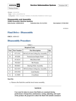
Disassembly and Assembly
318D2 Excavator Machine Systems
Media Number -UENR0198-03 Publication Date -01/12/2014 Date Updated -27/06/2018
i07255515
Final Drive - Disassemble
SMCS - 4050-015
Disassembly Procedure
Table 1
Required Tools
Tool Part Number Part Description Qty
A 477-3191 M14x2x18 mm Lifting Eye Assembly 2
B 1P-2420 Transmission Repair Stand 1
C
6V-8214 M6x20mm Bolt 2
9X-8267 M6 Washer 2
D 8H-0663 Bearing Puller Assembly 1
E 422-5474 M16x2x24mm Lifting Eye Assembly 2
F 439-3938 Link Bracket 3
G 1U-9889 Crossblock 1
Start By:
a. Remove the final drive and the travel motor assembly.
NOTICE
Care must be taken to ensure that fluids are contained during
performance of inspection, maintenance, testing, adjusting, and repair
of the product. Be prepared to collect the fluid with suitable containers
1/22
318D2 L Excavator TZS00001-UP (MACHINE) POWERED BY 3054C Engine(SEB...
2020/11/16
https://127.0.0.1/sisweb/sisweb/techdoc/techdoc_print_page.jsp?returnurl=/sis...
2. before opening any compartment or disassembling any component
containing fluids.
Refer to Special Publication, NENG2500, "Dealer Service Tool
Catalog" for tools and supplies suitable to collect and contain fluids on
Cat®
products.
Dispose of all fluids according to local regulations and mandates.
Personal injury can result from hydraulic oil pressure and hot oil.
Hydraulic oil pressure can remain in the hydraulic system after the
engine has been stopped. Serious injury can be caused if this pressure is
not released before any service is done on the hydraulic system.
Make sure all of the work tools have been lowered to the ground, and
the oil is cool before removing any components or lines. Remove the oil
filler cap only when the engine is stopped, and the filler cap is cool
enough to touch with your bare hand.
1. Thoroughly clean the outside of the final drive and travel motor prior to disassembly.
2. Remove the sprocket from the final drive and the travel motor assembly. The weight of the
sprocket is approximately 36 kg (79 lb).
Illustration 1 g06260984
3. Use Tooling (A) and a suitable lifting device to position final drive assembly (1) onto
Tooling (B). The weight of final drive assembly (1) is approximately 281 kg (620 lb).
2/22
318D2 L Excavator TZS00001-UP (MACHINE) POWERED BY 3054C Engine(SEB...
2020/11/16
https://127.0.0.1/sisweb/sisweb/techdoc/techdoc_print_page.jsp?returnurl=/sis...
3. Personal injury can result from being struck by parts propelled by a
released spring force.
Make sure to wear all necessary protective equipment.
Follow the recommended procedure and use all recommended tooling to
release the spring force.
Illustration 2 g06261012
Illustration 3 g06261017
4. Remove plug (2), spring (4), seat (3), and the O-ring seal.
Personal injury can result from being struck by parts propelled by a
released spring force.
3/22
318D2 L Excavator TZS00001-UP (MACHINE) POWERED BY 3054C Engine(SEB...
2020/11/16
https://127.0.0.1/sisweb/sisweb/techdoc/techdoc_print_page.jsp?returnurl=/sis...
4. Make sure to wear all necessary protective equipment.
Follow the recommended procedure and use all recommended tooling to
release the spring force.
Illustration 4 g06261029
Illustration 5 g06261032
5. Remove plug (5), spring (6), seat (7), stem assembly (8), and the O-ring seal.
Personal injury can result from being struck by parts propelled by a
released spring force.
Make sure to wear all necessary protective equipment.
Follow the recommended procedure and use all recommended tooling to
release the spring force.
4/22
318D2 L Excavator TZS00001-UP (MACHINE) POWERED BY 3054C Engine(SEB...
2020/11/16
https://127.0.0.1/sisweb/sisweb/techdoc/techdoc_print_page.jsp?returnurl=/sis...
5. Illustration 6 g06261260
Illustration 7 g06261275
6. Remove plug (9), spring (12), seat (11), spool (10), and the O-ring seal.
Illustration 8 g06261285
7. Remove adapter (13) and the O-ring seal.
5/22
318D2 L Excavator TZS00001-UP (MACHINE) POWERED BY 3054C Engine(SEB...
2020/11/16
https://127.0.0.1/sisweb/sisweb/techdoc/techdoc_print_page.jsp?returnurl=/sis...
6. Personal injury can result from being struck by parts propelled by a
released spring force.
Make sure to wear all necessary protective equipment.
Follow the recommended procedure and use all recommended tooling to
release the spring force.
Illustration 9 g06261336
Illustration 10 g06261344
8. Remove plug (14), spring (16), valve (15), and the O-ring seal.
Personal injury can result from being struck by parts propelled by a
released spring force.
Make sure to wear all necessary protective equipment.
Follow the recommended procedure and use all recommended tooling to
release the spring force.
6/22
318D2 L Excavator TZS00001-UP (MACHINE) POWERED BY 3054C Engine(SEB...
2020/11/16
https://127.0.0.1/sisweb/sisweb/techdoc/techdoc_print_page.jsp?returnurl=/sis...
7. Illustration 11 g06261519
Illustration 12 g06261532
9. Remove plug (17), spring (19), valve (18), and the O-ring seal.
Personal injury can result from being struck by parts propelled by a
released spring force.
Make sure to wear all necessary protective equipment.
Follow the recommended procedure and use all recommended tooling to
release the spring force.
7/22
318D2 L Excavator TZS00001-UP (MACHINE) POWERED BY 3054C Engine(SEB...
2020/11/16
https://127.0.0.1/sisweb/sisweb/techdoc/techdoc_print_page.jsp?returnurl=/sis...
8. Illustration 13 g06261538
Illustration 14 g06261539
10. Remove plugs (20) and the O-ring seals.
11. Remove plugs (21), springs (23), valves (22), and the O-ring seals.
Personal injury can result from being struck by parts propelled by a
released spring force.
Make sure to wear all necessary protective equipment.
Follow the recommended procedure and use all recommended tooling to
release the spring force.
8/22
318D2 L Excavator TZS00001-UP (MACHINE) POWERED BY 3054C Engine(SEB...
2020/11/16
https://127.0.0.1/sisweb/sisweb/techdoc/techdoc_print_page.jsp?returnurl=/sis...
9. Illustration 15 g06261563
12. Remove bolts (24) and valve body (25).
Illustration 16 g06263306
Port plate (28) may still be adhered to the barrel assembly.
13. Remove springs (26), port plate (28), and O-ring seals (27).
Illustration 17 g06261586
14. Remove bearing (29).
15. Remove O-ring seal (30).
9/22
318D2 L Excavator TZS00001-UP (MACHINE) POWERED BY 3054C Engine(SEB...
2020/11/16
https://127.0.0.1/sisweb/sisweb/techdoc/techdoc_print_page.jsp?returnurl=/sis...
10. Illustration 18 g06261622
16. Use Tooling (C) and suitable prying devices to remove piston assembly (31).
Illustration 19 g06261625
17. Remove O-ring seal (32) and O-ring seal (33).
Illustration 20 g06261647
10/22
318D2 L Excavator TZS00001-UP (MACHINE) POWERED BY 3054C Engine(SE...
2020/11/16
https://127.0.0.1/sisweb/sisweb/techdoc/techdoc_print_page.jsp?returnurl=/sis...
11. Illustration 21 g06261665
18. Remove separator plates (34) and friction plates (35). Note the alternating order of separator
plates (34) and friction plates (35) for assembly purposes.
Illustration 22 g06261896
19. Remove barrel assembly (36). Do not allow the components of barrel assembly (36) to
come apart while you remove barrel assembly (36). The components of barrel assembly (36)
must be reinstalled in the original positions.
Illustration 23 g06261908
20. Remove piston assemblies (37) and retainer (38).
11/22
318D2 L Excavator TZS00001-UP (MACHINE) POWERED BY 3054C Engine(SE...
2020/11/16
https://127.0.0.1/sisweb/sisweb/techdoc/techdoc_print_page.jsp?returnurl=/sis...
12. Note: Mark the component locations for assembly purposes before you disassemble the
barrel assembly.
Personal injury can result from being struck by parts propelled by a
released spring force.
Make sure to wear all necessary protective equipment.
Follow the recommended procedure and use all recommended tooling to
release the spring force.
Illustration 24 g06261915
21. Remove guide (39).
Illustration 25 g06261922
22. Remove springs (40).
12/22
318D2 L Excavator TZS00001-UP (MACHINE) POWERED BY 3054C Engine(SE...
2020/11/16
https://127.0.0.1/sisweb/sisweb/techdoc/techdoc_print_page.jsp?returnurl=/sis...
13. Illustration 26 g06261927
23. Put location marks on swashplate (41) for assembly purposes. Remove swashplate (41).
Personal injury can result from being struck by parts propelled by a
released spring force.
Make sure to wear all necessary protective equipment.
Follow the recommended procedure and use all recommended tooling to
release the spring force.
Illustration 27 g06261980
13/22
318D2 L Excavator TZS00001-UP (MACHINE) POWERED BY 3054C Engine(SE...
2020/11/16
https://127.0.0.1/sisweb/sisweb/techdoc/techdoc_print_page.jsp?returnurl=/sis...
14. Illustration 28 g06261983
24. Remove shaft assembly (42), keys (44), piston (43), and spring (45).
Illustration 29 g06261987
25. Use a suitable press and Tooling (D) to remove bearing (46) off the shaft assembly.
Illustration 30 g06262009
14/22
318D2 L Excavator TZS00001-UP (MACHINE) POWERED BY 3054C Engine(SE...
2020/11/16
https://127.0.0.1/sisweb/sisweb/techdoc/techdoc_print_page.jsp?returnurl=/sis...
15. Illustration 31 g06262033
26. Use Tooling (E) and a suitable lifting device to remove final drive assembly (47) from
Tooling (B) and reposition final drive assembly (47) as shown. The weight of final drive
assembly (47) is approximately 240 kg (530 lb).
Illustration 32 g06262046
27. Remove drain plugs (48), bolts (49), and cover (50).
Illustration 33 g06262473
28. Use Tooling (F) and a suitable lifting device to remove carrier assembly (51). The weight of
carrier assembly (51) is approximately 27 kg (60 lb).
15/22
318D2 L Excavator TZS00001-UP (MACHINE) POWERED BY 3054C Engine(SE...
2020/11/16
https://127.0.0.1/sisweb/sisweb/techdoc/techdoc_print_page.jsp?returnurl=/sis...
17. Illustration 37 g06262792
31. Remove sun gear (58).
Illustration 38 g06262846
32. Use Tooling (F) and a suitable lifting device to remove carrier assembly (59). The weight of
carrier assembly (59) is approximately 54 kg (120 lb).
Illustration 39 g06262855
17/22
318D2 L Excavator TZS00001-UP (MACHINE) POWERED BY 3054C Engine(SE...
2020/11/16
https://127.0.0.1/sisweb/sisweb/techdoc/techdoc_print_page.jsp?returnurl=/sis...
19. Illustration 43 g06262975
35. Use Tooling (F) and a suitable lifting device to remove final drive assembly (66) from
Tooling (B). The weight of final drive assembly (66) is approximately 154 kg (340 lb).
Illustration 44 g06263177
Illustration 45 g06263185
19/22
318D2 L Excavator TZS00001-UP (MACHINE) POWERED BY 3054C Engine(SE...
2020/11/16
https://127.0.0.1/sisweb/sisweb/techdoc/techdoc_print_page.jsp?returnurl=/sis...
20. Illustration 46 g06263201
36. Use Tooling (G) and a suitable press to remove washers (67).
Illustration 47 g06263235
37. Use Tooling (F) and a suitable lifting device to separate sprocket housing (68) and travel
motor housing (69). The weight of sprocket housing (68) is approximately 95 kg (210 lb).
The weight of travel motor housing (69) is approximately 59 kg (129 lb).
Illustration 48 g06263252
38. Remove duo cone seal (70).
20/22
318D2 L Excavator TZS00001-UP (MACHINE) POWERED BY 3054C Engine(SE...
2020/11/16
https://127.0.0.1/sisweb/sisweb/techdoc/techdoc_print_page.jsp?returnurl=/sis...
21. Illustration 49 g06263257
39. Remove bearing (71) and bearing (72).
Illustration 50 g06263266
40. Remove duo cone seal (73) and shim (74).
Illustration 51 g06263284
41. Remove lip seal (75).
Copyright 1993 - 2020 Caterpillar Inc.
All Rights Reserved.
Mon Nov 16 00:32:30 UTC+0800 2020
21/22
318D2 L Excavator TZS00001-UP (MACHINE) POWERED BY 3054C Engine(SE...
2020/11/16
https://127.0.0.1/sisweb/sisweb/techdoc/techdoc_print_page.jsp?returnurl=/sis...
22. Shutdown SIS
Previous Screen
Product: EXCAVATOR
Model: 318D2 L EXCAVATOR TZS
Configuration: 318D2 L Excavator TZS00001-UP (MACHINE) POWERED BY 3054C Engine
Disassembly and Assembly
318D2 Excavator Machine Systems
Media Number -UENR0198-03 Publication Date -01/12/2014 Date Updated -27/06/2018
i05453369
Final Drive - Assemble
SMCS - 4050-016
Assembly Procedure
Table 1
Required Tools
Tool Part Number Part Description Qty
A 1P-2420 Transmission Repair Stand 1
B 439-3938 Link Bracket 2
D 439-3940 Link Bracket 2
G 126-3994 Duo-Cone Seal Installer 1
H - Loctite C5-A Anti-Seize Lubricant
F - Loctite High Flex From-In-Place Gasket
Note: Cleanliness is an important factor. Before assembly, all parts should be cleaned in
cleaning fluid. Allow the parts to air dry. Wiping cloths or rags should not be used to dry
parts. Lint may be deposited on the parts which may cause later trouble. Inspect all parts. If
any parts are worn or damaged, use new parts for replacement. All disassembly and all
assembly procedures must be performed on a clean work surface and in a clean hydraulic
area. Keep cleaned parts covered and protected at all times.
Note: O-rings, gaskets, and seals should always be replaced. A used O-ring may not have
the same sealing properties as a new O-ring. Use 1U-6396 O-Ring Assembly Compound
during the assembly procedure.
Note: Apply a light film of hydraulic oil to all components before assembly.
1. Install the final drive sprocket if the sprocket was removed from the main housing.
1/13
318D2 L Excavator TZS00001-UP (MACHINE) POWERED BY 3054C Engine(SEB...
2020/11/16
https://127.0.0.1/sisweb/sisweb/techdoc/techdoc_print_page.jsp?returnurl=/sis...
23. 2. Refer to Disassembly and Assembly, "Final Drive Sprocket - Remove and Install".
Illustration 1 g00708215
3. Apply Tooling (H) to the outer diameter of the bearings.
4. Install bearings (32) and (33) in main housing (18) with a suitable press.
5. Make sure that bearing (32) and bearing (33) contact the counter bore in the main housing.
6. Use the following procedure to preload the bearings and determine the correct thickness of
shims.
Illustration 2 g00713058
a. Fasten Tooling (D) and a suitable lifting device to main housing (18). Install the main
housing on the motor housing.
b. Put the main housing and the motor housing in a suitable press.
2/13
318D2 L Excavator TZS00001-UP (MACHINE) POWERED BY 3054C Engine(SEB...
2020/11/16
https://127.0.0.1/sisweb/sisweb/techdoc/techdoc_print_page.jsp?returnurl=/sis...
24. Illustration 3 g00709278
(a) Bearing surface
(b) Housing surface
c. Use a suitable press and a spacer in order to apply a load of 4000 kg (8819 lb) on the
bearings. Rotate the housing in order to seat the bearings.
d. Reduce the load on the bearings to 1000 ± 100 kg (2205 ± 221 lb).
e. Use a depth micrometer in order to measure the step length between the bearing
surface and the housing surface. Take measurements at several different locations
around the housing. Compute the average of the measured dimensions and record the
number. Call this Dimension (Y).
Illustration 4 g00709276
f. Use a depth micrometer in order to measure the step length of gear (26). Take
measurements at several different locations around the gear. Compute the average of
the measured dimensions and record the number. Call this Dimension (X).
g. The thickness of the shims is equal to (X − Y) ± 0.05 mm (0.002 inch).
Note: Use no more than two shims. If two shims are required, install the thinner shim
next to the gear.
h. Remove the main housing from the motor housing.
3/13
318D2 L Excavator TZS00001-UP (MACHINE) POWERED BY 3054C Engine(SEB...
2020/11/16
https://127.0.0.1/sisweb/sisweb/techdoc/techdoc_print_page.jsp?returnurl=/sis...
25. Illustration 5 g01021370
7. Use Tooling (G) in order to install Duo-Cone seal (31) in main housing (18). Refer to
Disassembly and Assembly, "Duo-Cone Conventional Seals - Install".
Note: The rubber seals and all surfaces that contact the seals must be clean and dry. After
installation of the seals, put clean SAE 30 oil on the contact surfaces of the metal seals.
Illustration 6 g01021371
8. Use Tooling (G) in order to install Duo-Cone seal (29) in motor housing (28).
Illustration 7 g00708214
4/13
318D2 L Excavator TZS00001-UP (MACHINE) POWERED BY 3054C Engine(SEB...
2020/11/16
https://127.0.0.1/sisweb/sisweb/techdoc/techdoc_print_page.jsp?returnurl=/sis...
26. 9. Apply Tooling (H) to the surfaces that contact pins (30).
10. Install alignment pins (30).
Note: Do not damage the Duo-Cone seals in the main housing or in the motor housing
during the assembly of the two components. After installation of the main housing on the
motor housing, there will be a small gap between the components. The gap is caused by the
Duo-Cone seals. This gap will be eliminated during installation of gear (26).
Illustration 8 g00713058
11. Fasten Tooling (D) and a suitable lifting device to main housing (18). Install the main
housing on the motor housing.
Illustration 9 g00708211
12. Install shims (27) that were determined in Step 6.g in the main housing.
Note: If two shims are required, install the thinner shim next to the gear.
5/13
318D2 L Excavator TZS00001-UP (MACHINE) POWERED BY 3054C Engine(SEB...
2020/11/16
https://127.0.0.1/sisweb/sisweb/techdoc/techdoc_print_page.jsp?returnurl=/sis...
27. Suggest:
If the above button click is invalid.
Please download this document
first, and then click the above link
to download the complete manual.
Thank you so much for reading
28. Illustration 10 g00708187
13. Install gear (26).
14. Install bolts (25) in gear (26). Install the bolts in an even pattern until the gear is seated
against the bearing. Tighten bolts (25) in a crisscross pattern.
Illustration 11 g00708186
15. Install O-ring seal (24) to main housing (18).
Illustration 12 g00708175
16. Assemble carrier assembly (15), as follows.
6/13
318D2 L Excavator TZS00001-UP (MACHINE) POWERED BY 3054C Engine(SEB...
2020/11/16
https://127.0.0.1/sisweb/sisweb/techdoc/techdoc_print_page.jsp?returnurl=/sis...