
Recommended
More Related Content
Similar to Design Studio 6 Public Bath
Similar to Design Studio 6 Public Bath (20)
Recently uploaded
Recently uploaded (20)
Design Studio 6 Public Bath
- 3. ABOUT ME Zacc Lim Xin Yi Architectural Student 23 27/01/1999 011-31932495 xinyi8778@gmail.com UCSI University Bachelor of Science (Hons) in Architecture School of Architecture and Built environment
- 4. CONTENT JULY 2022 01 Site Introduction Site Demarcation User Group Studies Cultural Studies Contextual Studies 02 Metanoia "Warm Up" Design Thinking Proposal 03 Literature Review Literature Review Frame Work Site Reaction Narrative Site Perception 04 Site Analysis Site Vignettes Urban Strategies Design Concept and intention Proposed Program Site & Program Strategies 05 Preliminary Design Phase Final Project Perspective Public Bath of Fiki 06 Working Drawing Detail Drawing Services Technical Report
- 5. Site Introduction Site Demarcation User Group Studies Cultural Studies Contextual Studies Metanoia "Warm Up" Design Thinking Proposal Literature Review Literature Review Frame Work Site Reaction Narrative Site Perception Site Analysis Site Vignettes Urban Strategies Design Concept and intention Proposed Program Site & Program Strategies Preliminary Design Phase Final Project Perspective Public Bath of Fiki Working Drawing Detail Drawing Services Technical Report
- 24. Abstract MOdel
- 26. Metanoia xinyi8778@gmail.com P U B L I C B A T H O F F I K I
- 27. Site Introduction Site Demarcation User Group Studies Cultural Studies Contextual Studies Metanoia "Warm Up" Design Thinking Proposal Literature Review Literature Review Frame Work Site Reaction Narrative Site Perception Site Analysis Site Vignettes Urban Strategies Design Concept and intention Proposed Program Site & Program Strategies Preliminary Design Phase Final Project Perspective Public Bath of Fiki Working Drawing Detail Drawing Services Technical Report
- 32. Manifesto xinyi8778@gmail.com P U B L I C B A T H O F F I K I
- 33. Site Introduction Site Demarcation User Group Studies Cultural Studies Contextual Studies Metanoia "Warm Up" Design Thinking Proposal Literature Review Literature Review Frame Work Site Reaction Narrative Site Perception Site Analysis Site Vignettes Urban Strategies Design Concept and intention Proposed Program Site & Program Strategies Preliminary Design Phase Final Project Perspective Public Bath of Fiki Working Drawing Detail Drawing Services Technical Report
- 36. Site xinyi8778@gmail.com P U B L I C B A T H O F F I K I
- 37. Site Introduction Site Demarcation User Group Studies Cultural Studies Contextual Studies Metanoia "Warm Up" Design Thinking Proposal Literature Review Literature Review Frame Work Site Reaction Narrative Site Perception Site Analysis Site Vignettes Urban Strategies Design Concept and intention Proposed Program Site & Program Strategies Preliminary Design Phase Final Project Perspective Public Bath of Fiki Working Drawing Detail Drawing Services Technical Report
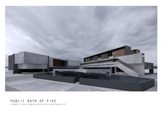
- 42. Public Bath xinyi8778@gmail.com P U B L I C B A T H O F F I K I
- 43. Site Introduction Site Demarcation User Group Studies Cultural Studies Contextual Studies Metanoia "Warm Up" Design Thinking Proposal Literature Review Literature Review Frame Work Site Reaction Narrative Site Perception Site Analysis Site Vignettes Urban Strategies Design Concept and intention Proposed Program Site & Program Strategies Preliminary Design Phase Final Project Perspective Public Bath of Fiki Working Drawing Detail Drawing Services Technical Report
- 58. TEA HOUSE ENJOYING TEA WITH PEACEFUL ENVIRONMENT SURROUND WITH NATURAL LIGHT AND WATER SOUND
- 59. RECEPTION LINEAR ELEMENT EMBRACE ENTRANCE WELCOMING , PATHWAY AND LEAD PEOPLE INSIDE THE SPACE
- 60. FOOT SPA AN INSIDE OUT SPACE FULL WITH NATURAL LIGHT, GREEN AND BLUE, DO YOU FEEL PEACE?
- 61. FOOT SPA FIRST FLOOR LEVEL VIEW ON DOUBLE VOLUME SPACE , SENSE OF SPACLOUS
- 62. FOOT SPA FEEL THE WIND PASS THROUGH YOUR SKIN, FEEL THE WARM THAT IN YOUR HEART
- 63. VENTILATION BLOCK ALOOW BETTER AIR CIRCULATION
- 64. TEA HOUSE FACADE HORIZONTAL SUPPORTED CONCRETE FACADE
- 65. ENTRANCE
- 67. CONNECTION
- 68. WALK WAY TO PUBLIC BATH
- 69. ACCOMODATION
- 70. STAIRCASE TO MANGEMENT OFFICE AND ACCOMODATION
- 72. Working Drawing xinyi8778@gmail.com P U B L I C B A T H O F F I K I
- 73. Site Introduction Site Demarcation User Group Studies Cultural Studies Contextual Studies Metanoia "Warm Up" Design Thinking Proposal Literature Review Literature Review Frame Work Site Reaction Narrative Site Perception Site Analysis Site Vignettes Urban Strategies Design Concept and intention Proposed Program Site & Program Strategies Preliminary Design Phase Final Project Perspective Public Bath of Fiki Working Drawing Detail Drawing Services Technical Report
- 94. 6300 4300 4300 31154 4300 4300 6400 3 3 5 0 1 3 2 5 0 6 5 5 0 3 3 5 0 4600 7500 3800 800 6300 23800 3800 23800 3700 6300 4400 10000 0 0 8 9 5 0 0 8 4 0 0 2 7 0 0 8 8 0 0 1 1 0 0 8 1 1 0 0 2 3 0 0 5 7 0 0 3 4 0 0 8 3 0 8 8 1100 7200 800 800 3800 800 2 1 8 0 0 2 8 0 0 4 3 0 0 3 1 0 0 4 3 0 0 3 8 0 0 6 6 0 0 875 1250 1175 1150 10725 3150 3125 X X WD/01 WD/01 X WD /01 X WD /01 -0.550 -2.70 TNB SUBSTATION SW ITCH TX GEN SET AHU ROOM M DF ROOM REFUSE TANK ROOM PUM P ROOM LOADING BAY M R P A 2 1 1: 1:2 0 RAM P FT FT FT FT SH SH FT SH FT FT SH FT BS BS BS BS SH SH BS FT BS BS BS BS FT BS BS SH BS BS SH FT FT BS UR UR UR FT SH FT SH BS BS FT SH FT BS FT SH BS FT TAP WC WC FT TAP FT SH FT TAP WC WC FT FT TAP FT TAP WC WC BS FT FT TAP WC WC WC WC WC WC WC FT FT FT FT FT FT FT FT FT FT FT FT FT TA P TA P TA P TA P TA P TA P TA P FT FT BS BS FT SH SH FT SH SH BS BS BS BS BS FT SH FT SH BS FT FT FT FT FT FT FT FT FT FT FT BS BS SH BS SH SH SH TA P TA P TA P WC WC WC FT SH SH WC WC TA P WC WC WC BS SH SH SH W . M . W . M . P P LV TA P TA P TA P W M. . P P WATER SUPPLY GROUND FLOOR PLAN SCALE 1 : 400
- 95. 4600 7500 3800 800 6300 23800 3800 23800 3700 3800 6300 4400 10000 0 0 8 9 5 0 0 8 4 0 0 2 7 0 0 8 8 0 0 1 1 0 0 8 1 1 0 0 2 3 0 0 5 7 0 0 3 4 0 0 8 3 0 8 8 1100 7200 800 800 800 6300 4300 4300 31154 4300 4300 6400 3 3 5 0 1 3 2 5 0 6 5 5 0 3 3 5 0 2 8 0 0 4 3 0 0 3 1 0 0 2 1 8 0 0 3 8 0 0 6 6 0 0 4 3 0 0 875 1250 1175 1150 10725 3150 3125 X X WD/01 WD/01 X WD /01 X WD /01 SH SK SH SH SK WC BS SK SK SH SK SH BS SH SK SH SK SK SK WC TAP WC WC WC WC WC WC BS BS WC WC WC WC BS SK FT FT FT SH SK FT FT FT FT FT SH FT SH SK BS FT FT BS FT BS SH SK SK BS FT FT TAP TAP TAP TAP TAP TAP BS FT BS BS SH SK TAP TAP TAP TAP TAP FT -2.70 M R P A 2 1 1: FT FT FT FT SH SH SH FT FT SH FT FT BS BS BS BS SH SH BS FT BS BS BS BS FT BS BS SH BS BS SH FT FT BS UR UR UR FT SH FT SH BS BS FT SH BS FT SH BS FT TAP WC WC FT TAP FT SH FT TAP WC WC FT FT TAP FT TAP WC WC BS FT FT TAP P WATER SUPPLY FIRST FLOOR PLAN SCALE 1 : 400
- 96. 10 6300 4300 4300 31154 4300 6400 3 3 5 0 1 3 2 5 0 6 5 5 0 3 3 5 0 4300 4600 7500 3800 800 6300 23800 3800 23800 3700 3800 6300 4400 10000 0 0 8 9 5 0 0 8 4 0 0 2 7 0 0 8 8 0 0 1 1 0 0 8 1 1 0 0 2 3 0 0 5 7 0 0 3 4 0 0 8 3 0 8 8 1100 7200 800 800 800 2 8 0 0 4 3 0 0 3 1 0 0 4 3 0 0 2 1 8 0 0 3 8 0 0 6 6 0 0 875 1250 1175 10725 3150 3125 1150 1 0 1 0 2° 2° 2° 2° P WATER SUPPLY ROOF PLAN SCALE 1 : 400
- 97. APRON LV. APRON LV. CEILING LV. CEILING LV. CEILING LV. CEILING LV. CEILING LV. GROUND LV. GROUND LV. APRON LV. CEILING LV. CEILING LV. GROUND LV. ROOF FLOOR LV. ATTIC FLOOR LV. ROOF FLOOR LV. FIRST FLOOR LV. THIRD FLOOR LV. SECOND FLOOR LV. GROUND FLOOR LV. GROUND FLOOR LV. ROOF FLOOR LV. FIRST FLOOR LV. GROUND FLOOR LV. 1.6M M X 1.5M (H) NOM CAP : 400GAL 1.6M X 1.5M (H) NOM CAP : 400GAL 1.6M X 1.5M (H) NOM CAP : 400GAL 1.6M X 1.5M (H) NOM CAP : 400GAL M 1.6M X 1.5M (H) NOM CAP : 400GAL 1.6M 1.6M X 1.5M (H) NOM CAP : 400GAL X 1.5M (H) NOM CAP : 400GAL M P P P 75MM UPVC PIPE 75MM UPVC PIPE 75MM UPVC PIPE 75MM UPVC PIPE 75MM UPVC PIPE 75MM UPVC PIPE 75MM UPVC PIPE 75MM UPVC PIPE 75MM UPVC PIPE 75MM UPVC PIPE 75MM UPVC PIPE OUTDOOR POND TANK ROOM ENTRANCE POND PUMP ROOM FEMALE PUBLIC TOILET UNIT 25 UNIT 13 UNIT 01 CO-KITCHEN 1 MALE TOILET MALE TOILET UNIT 26 UNIT 14 UNIT 02 FEMALE PUBLIC BATH CO-KITCHEN 2 OKU TOILET OKU TOILET UNIT 27 UNIT 15 UNIT 03 FEMALE TOILET UNIT 28 UNIT 16 UNIT 04 FEMALE TOILET FEMALE TOILET MALE PUBLIC TOILET UNIT 29 UNIT 17 UNIT 05 MALE TOILET MALE PUBLIC BATH COOL BATH COOL BATH UNIT 30 UNIT 18 UNIT 06 OKU TOILET UNIT 31 UNIT 19 UNIT 07 FOOT SPA UNIT 32 UNIT 20 UNIT 08 UNIT 33 UNIT 21 UNIT 09 FIRE BATH FIRE BATH UNIT 34 UNIT 22 UNIT 10 UNIT 35 UNIT 23 UNIT 11 UNIT 36 UNIT 24 UNIT 12 GROTTO BATH GROTTO BATH LAUNDRY LAUNDRY P PUBLIC BATH ACCOMODATION HOMELESS PUBLIC BATH WATER SUPPLY SCHEMATIC SYSTEM SCALE 1 : 400
- 98. 6300 4300 4300 31154 4300 4300 6400 3 3 5 0 1 3 2 5 0 6 5 5 0 3 3 5 0 4600 7500 3800 800 6300 23800 3800 23800 3700 6300 4400 10000 0 0 8 9 5 0 0 8 4 0 0 2 7 0 0 8 8 0 0 1 1 0 0 8 1 1 0 0 2 3 0 0 5 7 0 0 3 4 0 0 8 3 0 8 8 1100 7200 800 800 3800 800 2 1 8 0 0 2 8 0 0 4 3 0 0 3 1 0 0 4 3 0 0 3 8 0 0 6 6 0 0 875 1250 1175 1150 10725 3150 3125 X X WD/01 WD/01 X WD /01 X WD /01 FT FT FT FT SH SH SH SH FT FT FT FT BS BS BS BS FT FT SH FT FT BS FT FT SH FT FT TAP SH BS FT FT BS BS BS WC BS BS BS FT BS BS FT FT FT FT FT TAP WC WC BS BS TAP FT SH FT TAPFT WC BS FT FT SH TAP TAP FT TAPFT FT WC WC UR UR UR FT TAP BS FT FT FT WC FT FT FT FT FT BS BS W C FT FT FT TA P TA P BS FT SH BS TA P TA P TA P GT BS BS GT BS BS BS BS BS FT FT FT WC WC FT FT FT FT FT FT FT FT FT FT FT FT FT TA P TA P WC WC WC TA P FT BS SH FT FT SH SH BS SH SH SH FT FT FT FT FT FT FT FT FT FT FT FT FT SH SH WC WC TA P TA P TA P TA P WC WC TA P FT WC BS BS SH SH SH SH BS SH SH SH TA P TA P SEWERAGE GROUND FLOOR PLAN SCALE 1 : 400
- 99. 4600 7500 3800 800 6300 23800 3800 23800 3700 3800 6300 4400 10000 0 0 8 9 5 0 0 8 4 0 0 2 7 0 0 8 8 0 0 1 1 0 0 8 1 1 0 0 2 3 0 0 5 7 0 0 3 4 0 0 8 3 0 8 8 1100 7200 800 800 800 6300 4300 4300 31154 4300 4300 6400 3 3 5 0 1 3 2 5 0 6 5 5 0 3 3 5 0 2 8 0 0 4 3 0 0 3 1 0 0 2 1 8 0 0 3 8 0 0 6 6 0 0 4 3 0 0 875 1250 1175 1150 10725 3150 3125 X X WD/01 WD/01 X WD /01 X WD /01 FT FT FT FT SH SH SH SH FT FT FT FT BS BS BS BS FT FT SH BS FT FT SH FT FT TAP SH BS BS FT BS BS BS WC BS BS FT BS BS FT FT FT FT TAP WC WC BS BS TAP FT SH FT TAPFT WC BS FT FT SH TAP TAP FT TAPFT BS WC WC UR UR UR FT TAP FT FT WC FT FT BS BS W C W C FT BS FT FT FT W C W C FT W C W C FT FT BS FT W C W C FT W C W C FT SK FT FT W C W C BS SH SH SH SK SK BS SH SH SH SK SK BS SH SH SH SK TA P BS SK SH BS BS SK SK SH SH BS BS SK SK BS SK SK SK SH SK BS FT FT FT FT SEWERAGE FIRST FLOOR PLAN SCALE 1 : 400
- 100. 10 6300 4300 4300 31154 4300 6400 3 3 5 0 1 3 2 5 0 6 5 5 0 3 3 5 0 4300 4600 7500 3800 800 6300 23800 3800 23800 3700 3800 6300 4400 10000 0 0 8 9 5 0 0 8 4 0 0 2 7 0 0 8 8 0 0 1 1 0 0 8 1 1 0 0 2 3 0 0 5 7 0 0 3 4 0 0 8 3 0 8 8 1100 7200 800 800 800 2 8 0 0 4 3 0 0 3 1 0 0 4 3 0 0 2 1 8 0 0 3 8 0 0 6 6 0 0 875 1250 1175 10725 3150 3125 1150 1 0 1 0 2° 2° 2° 2° SEWERAGE ROOF PLAN SCALE 1 : 400
- 101. APRON LV. APRON LV. CEILING LV. CEILING LV. CEILING LV. CEILING LV. CEILING LV. GROUND LV. GROUND LV. APRON LV. CEILING LV. CEILING LV. ROOF FLOOR LV. ROOF FLOOR LV. FIRST FLOOR LV. ATTIC FLOOR LV. GROUND LV. THIRD FLOOR LV. SECOND FLOOR LV. GROUND FLOOR LV. GROUND FLOOR LV. FIRST FLOOR LV. ROOF FLOOR LV. GROUND FLOOR LV. UNIT 25 UNIT 13 UNIT 01 CO-KITCHEN 1 OUTDOOR POND ENTRANCE POND UNIT 26 UNIT 14 UNIT 02 CO-KITCHEN 2 FEMALE PUBLIC TOILET UNIT 27 UNIT 15 UNIT 03 MALE TOILET MALE TOILET FEMALE TOILET UNIT 28 UNIT 16 UNIT 04 FEMALE PUBLIC BATH OKU TOILET OKU TOILET UNIT 29 UNIT 17 UNIT 05 MALE TOILET FEMALE TOILET FEMALE TOILET MALE PUBLIC TOILET UNIT 30 UNIT 18 UNIT 06 OKU TOILET MALE PUBLIC BATH COOL BATH COOL BATH UNIT 31 UNIT 19 UNIT 07 UNIT 32 UNIT 20 UNIT 08 FOOT SPA UNIT 33 UNIT 21 UNIT 09 UNIT 34 UNIT 22 UNIT 10 UNIT 35 UNIT 23 UNIT 11 FIRE BATH FIRE BATH UNIT 36 UNIT 24 UNIT 12 LAUNDRY PET WASH GROTTO BATH GROTTO BATH LAUNDRY LAUNDRY F.T F.T F.T F.T GT F.T F.T F.T F.T F.T F.T F.T GUTTER F.T F.T F.T F.T F.T F.T GT F.T F.T F.T F.T F.T F.T F.T F.T F.T F.T F.T F.T F.T F.T F.T F.T F.T F.T F.T F.T F.T GUTTER F.T F.T F.T F.T F.T F.T F.T F.T F.T F.T F.T F.T F.T F.T F.T F.T F.T F.T F.T F.T F.T F.T F.T F.T F.T F.T F.T F.T F.T F.T F.T GUTTER F.T F.T F.T F.T F.T F.T F.T F.T F.T F.T F.T F.T F.T F.T F.T F.T F.T F.T F.T F.T F.T F.T F.T F.T F.T F.T F.T GUTTER F.T F.T F.T F.T F.T F.T F.T F.T F.T F.T F.T F.T F.T F.T F.T F.T F.T F.T F.T F.T F.T F.T F.T F.T F.T F.T F.T F.T F.T F.T F.T F.T F.T F.T F.T F.T F.T F.T F.T F.T F.T F.T F.T F.T F.T F.T F.T F.T F.T F.T F.T F.T F.T F.T F.T F.T F.T F.T F.T F.T F.T F.T F.T F.T F.T F.T F.T F.T F.T F.T F.T F.T F.T F.T G.T G.T G.T F.T F.T F.T F.T F.T F.T F.T F.T F.T F.T EXISTING MANHOLE 1 EXISTING MANHOLE 1 EXISTING MANHOLE 1 SEPTIC TANK WITH 102MM DIA FROM MAINHOLES UPVC WASTE PIPE DISCHARGE DISCHARGE SOAKAWAY PIT FROM SEPTIC TANK PIPE DISCHARGED TO DRAIN RESERVE 152MM DIA. UPVC SOIL SEPTIC TANK WITH 102MM DIA UPVC WASTE PIPE DISCHARGE FROM MAINHOLES DISCHARGE SOAKAWAY PIT FROM SEPTIC TANK PIPE DISCHARGED TO DRAIN RESERVE 152MM DIA. UPVC SOIL SEPTIC TANK WITH 102MM DIA UPVC WASTE PIPE DISCHARGE FROM MAINHOLES DISCHARGE SOAKAWAY PIT FROM SEPTIC TANK PIPE DISCHARGED TO DRAIN RESERVE 152MM DIA. UPVC SOIL VENT PIPE VENT PIPE VENT PIPE VENT PIPE VENT PIPE VENT PIPE VENT PIPE UPVC COWL VENT VENT PIPE 200MM ABOVE ROOF LEVEL UPVC COWL VENT 100mm DIA UPVC SOIL PIPE VENT PIPE 200MM ABOVE ROOF LEVEL UPVC COWL VENT VENT PIPE 200MM ABOVE ROOF LEVEL UPVC COWL VENT VENT PIPE 200MM ABOVE ROOF LEVEL SEWERAGE SCHEMATIC SYSTEM SCALE 1 : 400
- 102. 4600 7500 3800 800 6300 23800 3800 23800 3700 3800 6300 4400 10000 0 0 8 9 5 0 0 8 4 0 0 2 7 0 0 8 8 0 0 1 1 0 0 8 1 1 0 0 2 3 0 0 5 7 0 0 3 4 0 0 8 3 0 8 8 1100 7200 800 800 800 6300 4300 4300 31154 4300 4300 6400 3 3 5 0 1 3 2 5 0 6 5 5 0 3 3 5 0 2 8 0 0 4 3 0 0 3 1 0 0 2 1 8 0 0 3 8 0 0 6 6 0 0 4 3 0 0 875 1250 1175 1150 10725 3150 3125 X X WD/01 WD/01 X WD /01 X WD /01 A A A A A A A A A A A A A A A A A A A A A A A A A A A A A A A A A A A A A A A A A A A A A A A A A A A A DP DP A A A A A A A A DP A A A A A A A A A A A A DP A HR DP HR A A A A A A A A A A A A DP A A A A A A A A DP A DP A A A A A A A A A A A A A A A A A A A A A A A A A A A A DP A A A A A A A A A A A A A A A A A A A A A A DP A A A HR A A A A A A A A A A A A HR A A A A A A A A DP A DP DP A A A A A A A DP A A A A A A A HR A A DP A A A A A A A A A A A A A A A A A A A A A A A A A A A A A A A A A A A A A A A A A A A A A A A A A A A A A A A A A A A A A A A A A A DP A A A A A A A A A A A A A A A A A A A A A A DP A A A A A A DP DP A A A A A A A DP H R H R HR A DP BOMBA FIRST FLOOR PLAN SCALE 1 : 400
- 103. 6300 4300 4300 31154 4300 4300 6400 3 3 5 0 1 3 2 5 0 6 5 5 0 3 3 5 0 4600 7500 3800 800 6300 23800 3800 23800 3700 6300 4400 10000 0 0 8 9 5 0 0 8 4 0 0 2 7 0 0 8 8 0 0 1 1 0 0 8 1 1 0 0 2 3 0 0 5 7 0 0 3 4 0 0 8 3 0 8 8 1100 7200 800 800 3800 800 2 1 8 0 0 2 8 0 0 4 3 0 0 3 1 0 0 4 3 0 0 3 8 0 0 6 6 0 0 875 1250 1175 1150 10725 3150 3125 X X WD/01 WD/01 X WD /01 X WD /01 A A A A A A A A A A A A A A A A A A A A A A A A A A A A A A A A A A DP A A A A A A A A DP HR A A A A A A A A HR A A A DP DP A A A A A A A A A A A A A A A A A A A A A A DP HR DP A A A A A A A A A DP A A A A A A A A A DP A A A A A A A A A A A A A A A A HR A A A A A A A A A A A A A A A A A DP A A A A A A A A A A A A A A A HR A A A A A DP A A A A A A A A A A A A A A A A DP A A A A A A A DP A A A A A A A A DP A A A A A A A A A A A A A A A A A A A A A A A A A A A DP A DP A A A A A A A A A A A A A A A A A A DP A A DP A A A A A A A DP A A A A A A A A A A R H DP H R H R H R A DP BOMBA GROUND FLOOR PLAN SCALE 1 : 400
- 104. At least 11 nos of recessed lightings are required to achieve the standard requirement of illuminance recommended by MS1525 SPACE : RECEPTION AREA Interior Perspective Floor Plan Ligthing Study 1 2 3 4 5 Colour Pattern Ceiling Material and Specification White Finishing Gypsum Reflective Factor 85 Wall White Paster 40 Glass Light Blue Glass 8 Floor Light GREY CONCRETE 30 300MM THK. BRICK WALL WITH CEMENT RENDER FINIEHSES TO ENGR'S DETAIL 1 2 3 4 5 800MM(W) CAST IN SITU CONCRETE TABLE TO ARCH'S DETAIL 150MM(H) X 255MM(W) STEP TO ARCH'S DETSIL 1:12 RAMP 7200MM(L) TO ENGR'S DETAIL 150MM THK. CANTILIVER CONCRETE WALL TO ARCH'S DETAIL Day Light Artificial Light Study Dimension of Space Length (L) = 10.8 m Width (W) = 6.5 m Total floor area Types of Lighting Fixture No. of lamps in each luminaries (n) Lumen (F) Height of luminaries Height of working plane Height difference (Hm) Room index Assumption of reflectance value Utilization Factor (UF) Maintenance factor (MF) Standard illuminance, E No. of luminaries required (N) Spacing between luminaries Area = 10.8 x 6.5 m = 70.2m² Downlight 1 4000lm 4000mm 2000mm 4000mm - 2000mm = 2000mm k = L x W Hm (L+W) k = 10.8 x 6.5 2 (10.8+6.5) k = 70.2 34.6 k = 2.03 Ceiling : Wall : Floor = 70 : 50 : 20 When k = 2.03 , UF = 0.63 0.8 ( normal condition with AC) 300 lux N = EA F x n x UF x MF N = ( 300 x 70.2) 4000 x 1 x 0.62 x 0.8 N = 21060 1984 N = 11 nos Assume max. spacing between the luminaries to height ratio for the light=1.5 Smax = 1.5 x Hm = 1.5 x 2m = 3m Ventilation Study Temperature Study The 360° Airflow distribution creates uniform comfort throughout the space and the room remains comfortable even when the set temperature is raised by 1℃. AC System Layout Plan Calculation for natural ventilation required (Size of Opening) Total floor area x 10% = 70.2m² x 10% = 7.02m² Natural ventilation (Openings provided) Opening A = 3m x 1.2m = 3.6m² Opening B = 3 x 1.2m = 3.4m² Total Openings = A + B = 3.6 + 3.6 = 7.2 > 7.02m² Therefore, the openings provided comply with UBBL Clause 39: Natural Ventilation Minimum Requirement for ventilation. Dimension of Space Length (L) = 10.8 m Width (W) = 6.5 m Total floor area Area = 10.8 x 6.5 m = 70.2m² = 753.5ft² According to UBBL 41, the 3rd schedule of UBBL, the retail area requires 0.14m³ of air per minute per occupant (cmm) which is equal to 4.94CFM per occupant. BTU/Hr required in the space 753.5 x 25 = 18837.5 BTU/Hr Proposed AC has 19000 BTU/Hr 18837.5BTU/Hr /19000 = 0.991 nos. ≈ 1 nos CFM to Tons 1 Ton of Cooling = 400 CFM 1 Ton of Cooling = 19000 BTU/Hr Since only 1 nos of 19000 BTU/Hr AC is used, so a total of 19000 BTU/Hr is provided, 19000 BTU/Hr = 1 tons of cooling = 400 CFM There are approximately max. 25 occupants inside this room, 25 x 4.94= 123.5 CFM Therefore, the space is sufficient and approved for 1 nos of AC system to cool the space and appropriate for mechanical ventilation in the case in which the openings are closed. In conclusion, 1 nos of 4-way cassette 2 Hp of Air conditioning unit is used for the cooling purpose in this space. The split system is applied which 1 outdoor condensing unit to be installed to supply the 1 indoor evaporating unit. Air Conditioning Unit https://www.daikin.com.my/daikin_products/fcf-c-series/ Brand: DAIKIN Name: 4-WAY CASSETTE Model: FCF-C Series Horsepower = 2 HP Cooling capacity = 19000BTU/Hr Circulation airflow cools the entire area to deliver comfort that never feels cold. Evaporating indoor AC unit Condensing outdoor AC unit AC Ductwork Powder coated steel ceiling bracket and acrylic plastic shade Direct sunlight Maximum illumination Minimum illumination High Temperature Moderate Temperature Cold Temperature There are two main openings at the South-East facade for natural light to penetrate in and a clear river view
- 105. End thank you xinyi8778@gmail.com P U B L I C B A T H O F F I K I