
Recommended
More Related Content
Recently uploaded
Recently uploaded (20)
Featured
Featured (20)
Reseter Epson
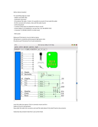
- 1. Add-on device (resetter) For assembling stage you need: - solderer and solder alloy - multimeter instrument - 25-conductor flat cable, 1 meter, (it is possible to use part of more wide flat cable) - DI-25m connector (25 contacts, male, with flat cable mount) - small wiring board - 7 resistors (rated values are depicted on electric circuit) - 4 Zener diodes C1-C4 (stabilitrons, use any 0.5w, 3.3v, like BZX55C 3V3) - 1 transistor T1 ( BC546C, BC547C or similar ones) - RJ45 socket Below you'll find electric circuit of add-on device. Wiring board is marked by semitransparent light-green color. On picture you'll find pinout for all used components. Insert flat cable (use approx. 0.5m) in connector mount and fix it. Solder all circuit on wiring board. Now solder flat cable from connector and small flat cable (about 0.3m) what'll lead to chip contactor. Study how chip contactor looks like in your printer head. Using suitable RJ45 socket it is possible to make some resemblance of original contactor by slightly breaking socket, then by cutting and bending necessary thin springy contacts similarly to original contactor. Then you must solder small flat cable to contactor. Use contacts pinout shown on chip picture.