3. Page No.Contents
Section 1 - General Information
1 - i 1 - i
Introduction
About this Manual .................................................................................... 1 - 1
Machine Model and Serial Number .................................................... 1 - 1
Using the Service Manual .................................................................. 1 - 1
Section Numbering ............................................................................. 1 - 1
Left Side, Right Side ........................................................................... 1 - 2
Cross References ............................................................................... 1 - 2
Identifying your Machine .......................................................................... 1 - 3
Machine Identification Plate ............................................................... 1 - 3
Typical Vehicle Identification Number ................................................. 1 - 3
Typical Product Identification Number ................................................ 1 - 4
Component Identification Plates ......................................................... 1 - 5
Standard Torque Settings
Zinc Plated Fasteners and Dacromet Fasteners ..................................... 1 - 7
Introduction ......................................................................................... 1 - 7
Bolts and Screws ................................................................................ 1 - 7
Hydraulic Connections ........................................................................... 1 - 11
'O' Ring Face Seal System ............................................................... 1 - 11
'Torque Stop' Hose System .............................................................. 1 - 14
Service Tools
Numerical List ........................................................................................ 1 - 15
Tool Detail Reference Section ............................................................... 1 - 16
Section B - Body and Framework ..................................................... 1 - 16
Section C - Electrics ......................................................................... 1 - 21
Section E- Hydraulics ....................................................................... 1 - 23
Section F - Transmission .................................................................. 1 - 25
Section G - Brakes ........................................................................... 1 - 28
Service Aids
Sealing and Retaining Compounds ....................................................... 1 - 29
Terms and Definitions
Colour Coding ........................................................................................ 1 - 31
Hydraulic Schematic Colour Codes .................................................. 1 - 31
Black and White Codes .................................................................... 1 - 32
Basic Operation
Preparation for Towing ........................................................................... 1 - 33
4. Section 1 - General Information
1 - 1 1 - 19803/4180-08
Introduction
About this Manual
Machine Model and Serial Number
This manual provides information for the following
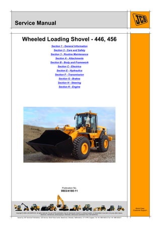
model(s) in the JCB machine range:
– 456 Wheeled Loading Shovel from 539000
– 446 Wheeled Loading Shovel from 540013.
Using the Service Manual
T11-004
This publication is designed for the benefit of JCB
Distributor Service Engineers who are receiving, or have
received, training by JCB Technical Training Department.
These personnel should have a sound knowledge of
workshop practice, safety procedures, and general
techniques associated with the maintenance and repair of
hydraulic earthmoving equipment.
The illustrations in this publication are for guidance only.
Where the machines differ, the text and/or the illustration
will specify.
General warnings in Section 2 are repeated throughout the
manual, as well as specific warnings. Read all safety
statements regularly, so you do not forget them.
Renewal of oil seals, gaskets, etc., and any component
showing obvious signs of wear or damage is expected as
a matter of course. It is expected that components will be
cleaned and lubricated where appropriate, and that any
opened hose or pipe connections will be blanked to
prevent excessive loss of hydraulic fluid and ingress of dirt.
Where a torque setting is given as a single figure it may be
varied by plus or minus 3%. Torque figures indicated are
for dry threads, hence for lubricated threads may be
reduced by one third.
The manufacturer's policy is one of continuous
improvement. The right to change the specification of the
machine without notice is reserved. No responsibility will
be accepted for discrepancies which may occur between
specifications of the machine and the descriptions
contained in this publication.
Finally, please remember above all else safety must come
first!
Section Numbering
T11-005
The manual is compiled in sections, the first three are
numbered and contain information as follows:
The remaining sections are alphabetically coded and deal
with Dismantling, Overhaul etc. of specific components, for
example:
Section contents, technical data, circuit descriptions,
operation descriptions etc. are inserted at the beginning of
each alphabetically coded section.
1 General Information - includes torque settings and
service tools.
2 Care and Safety - includes warnings and cautions
pertinent to aspects of workshop procedures etc.
3 Maintenance - includes service schedules and
recommended lubricants for all the machine.
A Attachments
B Body and Framework, etc.
5. Section 1 - General Information
Introduction
About this Manual
1 - 2 1 - 29803/4180-08
Left Side, Right Side
In this manual, 'left' A and 'right' B mean your left and right
when you are seated correctly in the machine.
T033800-1
Fig 1.
Cross References
T1-004_2
In this publication, page cross references are made by
presenting the subject title printed in bold, italic and
underlined. It is preceeded by the 'go to' symbol. The
number of the page upon which the subject begins, is
indicated within the brackets. For example: K Cross
References ( T 1-2).
6. Section 1 - General Information
Introduction
Identifying your Machine
1 - 3 1 - 39803/4180-08
Identifying your Machine
Machine Identification Plate
Your machine has an identification plate mounted as
shown. The serial numbers of the machine and its major
units are stamped on the plate.
Note: The machine model and build specification is
indicated by the PIN. Refer to Typical Product
Identification Number (PIN).
The serial number of each major unit is also stamped on
the unit itself. If a major unit is replaced by a new one, the
serial number on the identification plate will be wrong.
Either stamp the new number of the unit on the
identification plate, or simply stamp out the old number.
This will prevent the wrong unit number being quoted when
replacement parts are ordered.
The machine and engine serial numbers can help identify
exactly the type of equipment you have.
T033550-2
Fig 2.
Typical Vehicle Identification Number
1 World Manufacturer Identification, SLP = JCB
2 Machine Model, 456ZX
3 Year of Manufacture (P = 1993, R = 1994, S = 1995,
T = 1996, V = 1997, W = 1998, X = 1999, Y = 2000, 1
= 2001, 2 = 2002, 3 = 2003, 4 = 2004)
4 Manufacturers Location (E = England)
5 Machine Serial Number (0539001)
The serial number of each major unit is also stamped on
the unit itself. If a major unit is replaced by a new one, the
serial number on the identification plate will be wrong.
Either stamp the new number of the unit on the
identification plate, or simply stamp out the old number.
This will prevent the wrong unit number being quoted when
replacement parts are ordered.
The machine and engine serial numbers can help identify
exactly the type of equipment you have.
1 2 3 4 5
SLP 456 V E 539000
7. Section 1 - General Information
Introduction
Identifying your Machine
1 - 4 1 - 49803/4180-08
Typical Product Identification Number
T033160-1.
Fig 3.
1 World Manufacturer Identification (3 Digits)
2 Model Number (3 Digits)
3 Loader End Type (1 Digit)
4 Designation (1 Digit)
5 Check Letter (1 Digit)
The Check Letter is used to verify the authenticity of
the machine’s PIN.
6 Year of Manufacture (1 Digit)
7 Machine Serial Number (7 Digits)
Each machine has a unique serial number.
Note: On later models, the year of manufacture digit was
removed and the machine serial number was increased to
8 digits.
O = HT Loader End
Z = ZX Loader End
S = Farmmaster
O = None Farmmaster
I = India
7 = 2007 A = 2010
8 = 2008 B = 2011
9 = 2009 C = 2012
8. Section 1 - General Information
Introduction
Identifying your Machine
1 - 5 1 - 59803/4180-08
Component Identification Plates
Unit Identification
Fig 4.
The engine serial number is stamped on a plate 4Y which
is fastened to the right side of the cylinder block.
Fig 5.
The transmission serial number is stamped on plate 5Z as
shown.
9. Section 1 - General Information
Introduction
Identifying your Machine
1 - 6 1 - 69803/4180-08
FOPS Data Plate
!MWARNING
Do not use the machine if the falling objects protection
level provided by the structure is not sufficient for the
application. Falling objects can cause serious injury.
8-2-8-17
If the machine is used in any application where there is a
risk of falling objects then a falling-objects protective
structure (FOPS) must be installed. For further information
contact your JCB Dealer
The falling objects protection structure (FOPS) is fitted with
a dataplate. The dataplate indicates what level protection
the structure provides.
There are two levels of FOPS:
– Level I Impact Protection - impact strength for
protection from small falling objects (e.g. bricks, small
concrete blocks, hand tools) encountered in
operations such as highway maintenance,
landscaping and other construction site services.
– Level II Impact Protection - impact strength for
protection from heavy falling objects (e.g. trees,
rocks) for machines involved in site clearing,
overhead demolition or forestry.
ROPS Data Plate
!MWARNING
You could be killed or seriously injured if you operate
a machine with a damaged or missing ROPS/FOPS. If
the Roll Over Protection Structure (ROPS)/Falling
Objects Protection Structure (FOPS) has been in an
accident, do not use the machine until the structure
has been renewed. Modifications and repairs that are
not approved by the manufacturer may be dangerous
and will invalidate the ROPS/FOPS certification.
INT-2-1-9_6
!MWARNING
Seat Belts
The ROPS/FOPS is designed to give you protection in
an accident. If you do not wear your seat belt, you
could be thrown out of the machine and crushed. You
must wear a seat belt when using the machine. Fasten
the seat belt before starting the engine.
0153
Machines built to the ROPS/FOPS standard have a data
plate attached to the inside of the cab.
332-A5586
Fig 6.
J.C.B.CABSYSTEMS
LAKESIDEWORKS
ROCESTER
UTTOXETER,STAFFS
ST145JP
ENGLAND
427
437
457
FOPS:
COMPLIESTO
EN13627:2000
LEVEL2
CABPARTNo:
335/06840,335/09298
YEAR:
SERIALNo:
MAXIMUMUNLADEN
MASS26000Kg
JCBWHEELEDLOADER ROPS:
COMPLIESTO
EN13510:2000
ISO3471:1994
332/A5586
10. Section 1 - General Information
Standard Torque Settings
Zinc Plated Fasteners and Dacromet Fasteners
1 - 7 1 - 79803/4180-08
Standard Torque Settings
Zinc Plated Fasteners and Dacromet Fasteners
T11-002
Introduction
Some external fasteners on JCB machines are
manufactured using an improved type of corrosion
resistant finish. This type of finish is called Dacromet and
replaces the original Zinc and Yellow Plating used on
earlier machines.
The two types of fasteners can be readily identified by
colour and part number suffix. K Table 1. Fastener Types
( T 1-7).
Table 1. Fastener Types
Note: As the Dacromet fasteners have a lower torque
setting than the Zinc and Yellow fasteners, the torque
figures used must be relevant to the type of fastener.
Note: A Dacromet bolt should not be used in conjunction
with a Zinc or Yellow plated nut, as this could change the
torque characteristics of the torque setting further. For the
same reason, a Dacromet nut should not be used with a
Zinc or Yellow plated bolt.
Note: All bolts used on JCB machines are high tensile and
must not be replaced by bolts of a lesser tensile
specification.
Note: Dacromet bolts, due to their high corrosion
resistance are used in areas where rust could occur.
Dacromet bolts are only used for external applications.
They are not used in applications such as gearbox or
engine joint seams or internal applications.
Bolts and Screws
Use the following torque setting tables only where no
torque setting is specified in the text.
Note: Dacromet fasteners are lubricated as part of the
plating process, do not lubricate.
Torque settings are given for the following conditions:
Condition 1
– Un-lubricated fasteners
– Zinc fasteners
– Yellow plated fasteners
Condition 2
– Zinc flake (Dacromet) fasteners
– Lubricated zinc and yellow plated fasteners
– Where there is a natural lubrication. For example,
cast iron components
Verbus Ripp Bolts
Fig 7.
Torque settings for these bolts are determined by the
application. Refer to the relevant procedure for the
required settings.
Fastener
Type
Colour Part No. Suffix
Zinc and
Yellow
Golden finish 'Z' (e.g. 1315/3712Z)
Dacromet Mottled silver finish 'D' (e.g. 1315/3712D)
17. Page No.Contents
Section 2 - Care and Safety
2 - i 2 - i
Safety Notices
Important Information .............................................................................. 2 - 1
The Operator Manual ......................................................................... 2 - 1
Safety Warnings ................................................................................. 2 - 1
Safety Check List ..................................................................................... 2 - 2
Safety - Yours and Others .................................................................. 2 - 2
General Safety ................................................................................... 2 - 2
Operating Safety ................................................................................ 2 - 4
Maintenance Safety ............................................................................ 2 - 7
Safety Labels ......................................................................................... 2 - 13
Introduction ....................................................................................... 2 - 13
Safety Label Identification ................................................................ 2 - 14
Part Numbers and Descriptions ....................................................... 2 - 15
18. Section 2 - Care and Safety
2 - 1 2 - 19803/4180-08
Safety Notices
Important Information
T1-042
The Operator Manual
!MWARNING
You and others can be killed or seriously injured if you
operate or maintain the machine without first studying
the Operator Manual. You must understand and follow
the instructions in the Operator Manual. If you do not
understand anything, ask your employer or JCB
dealer to explain it.
INT-1-4-2
Do not operate the machine without an Operator Manual,
or if there is anything on the machine you do not
understand.
Treat the Operator Manual as part of the machine. Keep it
clean and in good condition. Replace the Operator Manual
immediately if it is lost, damaged or becomes unreadable.
Safety Warnings
In this publication and on the machine, there are safety
notices. Each notice starts with a signal word. The signal
word meanings are given below.
!MDANGER
Denotes an extreme hazard exists. If proper
precautions are not taken, it is highly probable that the
operator (or others) could be killed or seriously
injured.
INT-1-2-1
!MWARNING
Denotes a hazard exists. If proper precautions are not
taken, the operator (or others) could be killed or
seriously injured.
INT-1-2-2
!MCAUTION
Denotes a reminder of safety practices. Failure to
follow these safety practices could result in injury to
the operator (or others) and possible damage to the
machine.
INT-1-2-3
This safety alert system identifies
important safety messages in this
manual. When you see this symbol, be
alert, your safety is involved, carefully
read the message that follows, and inform
other operators.
19. Section 2 - Care and Safety
Safety Notices
Safety Check List
2 - 2 2 - 29803/4180-08
Safety Check List
P4-1004_3
Safety - Yours and Others
INT-1-3-1_3
All machinery can be hazardous. When a machine is
correctly operated and properly maintained, it is a safe
machine to work with. But when it is carelessly operated or
poorly maintained it can become a danger to you (the
operator) and others.
In this manual and on the machine you will find warning
messages. Read and understand them. They tell you of
potential hazards and how to avoid them. If you do not fully
understand the warning messages, ask your employer or
JCB distributor to explain them.
But safety is not just a matter of responding to the
warnings. All the time you are working on or with the
machine you must be thinking what hazards there might be
and how to avoid them.
Do not work with the machine until you are sure that you
can control it.
Do not start any job until you are sure that you and those
around you will be safe.
If you are unsure of anything, about the machine or the job,
ask someone who knows. Do not assume anything.
Remember
BE CAREFUL
BE ALERT
BE SAFE
General Safety
T1-043
!MWARNING
To operate the machine safely you must know the
machine and have the skill to use it. You must abide by
all relevant laws, health and safety regulations that
apply to the country you are operating in. The
Operator Manual instructs you on the machine, its
controls and its safe operation; it is not a training
manual. If you are a new operator, get yourself trained
in the skills of using a machine before trying to work
with it. If you don't, you will not do your job well, and
you will be a danger to yourself and others.
INT-1-4-1
!MWARNING
Care and Alertness
All the time you are working with or on the machine,
take care and stay alert. Always be careful. Always be
alert for hazards.
INT-1-3-5
!MWARNING
Clothing
You can be injured if you do not wear the proper
clothing. Loose clothing can get caught in the
machinery. Wear protective clothing to suit the job.
Examples of protective clothing are: a hard hat, safety
shoes, safety glasses, a well fitting overall, ear-
protectors and industrial gloves. Keep cuffs fastened.
Do not wear a necktie or scarf. Keep long hair
restrained. Remove rings, watches and personal
jewellery.
INT-1-3-6_2
!MWARNING
Alcohol and Drugs
It is extremely dangerous to operate machinery when
under the influence of alcohol or drugs. Do not
consume alcoholic drinks or take drugs before or
while operating the machine or attachments. Be aware
of medicines which can cause drowsiness.
INT-1-3-9_2
20. Thank you very much for
your reading. Please Click
Here. Then Get COMPLETE
MANUAL. NO WAITING
NOTE:
If there is no response to
click on the link above,
please download the PDF
document first and then
click on it.
21. Section 2 - Care and Safety
Safety Notices
Safety Check List
2 - 3 2 - 39803/4180-08
!MWARNING
Feeling Unwell
Do not attempt to operate the machine if you are
feeling unwell. By doing so you could be a danger to
yourself and those you work with.
8-1-2-4
!MWARNING
Mobile Phones
Switch off your mobile phone before entering an area
with a potentially explosive atmosphere. Sparks in
such an area could cause an explosion or fire
resulting in death or serious injury.
Switch off and do not use your mobile phone when
refuelling the machine.
INT-3-3-9
!MWARNING
Lifting Equipment
You can be injured if you use incorrect or faulty lifting
equipment. You must identify the weight of the item to
be lifted then choose lifting equipment that is strong
enough and suitable for the job. Make sure that lifting
equipment is in good condition and complies with all
local regulations.
INT-1-3-7_2
!MWARNING
Raised Equipment
Never walk or work under raised equipment unless it
is supported by a mechanical device. Equipment
which is supported only by a hydraulic device can
drop and injure you if the hydraulic system fails or if
the control is operated (even with the engine stopped).
Make sure that no-one goes near the machine while
you install or remove the mechanical device.
13-2-3-7_3
!MWARNING
Raised Machine
NEVER position yourself or any part of your body
under a raised machine which is not properly
supported. If the machine moves unexpectedly you
could become trapped and suffer serious injury or be
killed.
INT-3-3-7_1
!MDANGER
Lightning
Lightning can kill you. Do not use the machine if there
is lightning in your area.
5-1-1-2
!MWARNING
Machine Modifications
This machine is manufactured in compliance with
legislative and other requirements. It should not be
altered in any way which could affect or invalidate any
of these requirements. For advice consult your JCB
Distributor.
INT-1-3-10_2
22. Section 2 - Care and Safety
Safety Notices
Safety Check List
2 - 4 2 - 49803/4180-08
Operating Safety
!MWARNING
Machine Condition
A defective machine can injure you or others. Do not
operate a machine which is defective or has missing
parts. Make sure the maintenance procedures in this
manual are completed before using the machine.
INT-2-1-2_2
!MWARNING
Machine Limits
Operating the machine beyond its design limits can
damage the machine, it can also be dangerous. Do not
operate the machine outside its limits. Do not try to
upgrade the machine performance with unapproved
modifications.
INT-2-1-4
!MWARNING
Engine/Steering Failure
If the engine or steering fails, stop the machine as
quickly as possible. Do not operate the machine until
the fault has been corrected.
INT-2-1-5
!MWARNING
Exhaust Gases
Breathing the machine exhaust gases can harm and
possibly kill you. Do not operate the machine in closed
spaces without making sure there is good ventilation.
If possible, fit an exhaust extension. If you begin to
feel drowsy, stop the machine at once and get into
fresh air.
INT-2-1-10_2
!MWARNING
Work Sites
Work sites can be hazardous. Inspect the site before
working on it. You could be killed or injured if the
ground gives way under your machine or if piled
material collapses onto it. Check for potholes and
hidden debris, logs, ironwork etc. Any of these could
cause you to lose control of your machine. Check for
utilities such as electric cables (overhead and
underground), gas and water pipes etc. Mark the
positions of the underground cables and pipes. Make
sure that you have enough clearance beneath
overhead cables and structures.
INT-2-2-1_2
!MWARNING
Communications
Bad communications can cause accidents. Keep
people around you informed of what you will be doing.
If you will be working with other people, make sure any
hand signals that may be used are understood by
everybody. Work sites can be noisy, do not rely on
spoken commands.
INT-2-2-3
!MWARNING
Parking
An incorrectly parked machine can move without an
operator. Follow the instructions in the Operator
Manual to park the machine correctly.
INT-2-2-4_2
!MWARNING
Banks and Trenches
Banked material and trenches can collapse. Do not
work or drive too close to banks and trenches where
there is danger of collapse.
INT-2-2-5
!MWARNING
Before moving the machine onto the trailer, make sure
that the trailer and ramp are free from oil, grease and
ice. Remove oil, grease and ice from the machine
tyres. Make sure the machine will not foul on the ramp
angle. See Static Dimensions in SPECIFICATION
section for the minimum ground clearance of your
machine.
2-2-7-5_1