1. The document provides instructions for removing and installing various engine components of a 3406C diesel engine, including the spacer plate, valves, valve seat inserts, bridge dowels, valve guides, oil pan and plate, oil pump, and piston cooling tubes.
2. The instructions describe cleaning and preparing surfaces, using specific tools to remove and install components, and ensuring proper installation and operation after reassembly.
3. The overall process involves disassembling parts, cleaning surfaces, installing new parts as needed, and reassembling the engine, with the goal of properly servicing the 3406C diesel engine.
Symptoms like intermittent starting and key recognition errors signal potential problems with your Mercedes’ EIS. Use diagnostic steps like error code checks and spare key tests. Professional diagnosis and solutions like EIS replacement ensure safe driving. Consult a qualified technician for accurate diagnosis and repair.
In this presentation, we have discussed a very important feature of BMW X5 cars… the Comfort Access. Things that can significantly limit its functionality. And things that you can try to restore the functionality of such a convenient feature of your vehicle.
Things to remember while upgrading the brakes of your carjennifermiller8137
Upgrading the brakes of your car? Keep these things in mind before doing so. Additionally, start using an OBD 2 GPS tracker so that you never miss a vehicle maintenance appointment. On top of this, a car GPS tracker will also let you master good driving habits that will let you increase the operational life of your car’s brakes.
"Trans Failsafe Prog" on your BMW X5 indicates potential transmission issues requiring immediate action. This safety feature activates in response to abnormalities like low fluid levels, leaks, faulty sensors, electrical or mechanical failures, and overheating.
What Exactly Is The Common Rail Direct Injection System & How Does It WorkMotor Cars International
Learn about Common Rail Direct Injection (CRDi) - the revolutionary technology that has made diesel engines more efficient. Explore its workings, advantages like enhanced fuel efficiency and increased power output, along with drawbacks such as complexity and higher initial cost. Compare CRDi with traditional diesel engines and discover why it's the preferred choice for modern engines.
Core technology of Hyundai Motor Group's EV platform 'E-GMP'Hyundai Motor Group
What’s the force behind Hyundai Motor Group's EV performance and quality?
Maximized driving performance and quick charging time through high-density battery pack and fast charging technology and applicable to various vehicle types!
Discover more about Hyundai Motor Group’s EV platform ‘E-GMP’!
Comprehensive program for Agricultural Finance, the Automotive Sector, and Empowerment . We will define the full scope and provide a detailed two-week plan for identifying strategic partners in each area within Limpopo, including target areas.:
1. Agricultural : Supporting Primary and Secondary Agriculture
• Scope: Provide support solutions to enhance agricultural productivity and sustainability.
• Target Areas: Polokwane, Tzaneen, Thohoyandou, Makhado, and Giyani.
2. Automotive Sector: Partnerships with Mechanics and Panel Beater Shops
• Scope: Develop collaborations with automotive service providers to improve service quality and business operations.
• Target Areas: Polokwane, Lephalale, Mokopane, Phalaborwa, and Bela-Bela.
3. Empowerment : Focusing on Women Empowerment
• Scope: Provide business support support and training to women-owned businesses, promoting economic inclusion.
• Target Areas: Polokwane, Thohoyandou, Musina, Burgersfort, and Louis Trichardt.
We will also prioritize Industrial Economic Zone areas and their priorities.
Sign up on https://profilesmes.online/welcome/
To be eligible:
1. You must have a registered business and operate in Limpopo
2. Generate revenue
3. Sectors : Agriculture ( primary and secondary) and Automative
Women and Youth are encouraged to apply even if you don't fall in those sectors.
𝘼𝙣𝙩𝙞𝙦𝙪𝙚 𝙋𝙡𝙖𝙨𝙩𝙞𝙘 𝙏𝙧𝙖𝙙𝙚𝙧𝙨 𝙞𝙨 𝙫𝙚𝙧𝙮 𝙛𝙖𝙢𝙤𝙪𝙨 𝙛𝙤𝙧 𝙢𝙖𝙣𝙪𝙛𝙖𝙘𝙩𝙪𝙧𝙞𝙣𝙜 𝙩𝙝𝙚𝙞𝙧 𝙥𝙧𝙤𝙙𝙪𝙘𝙩𝙨. 𝙒𝙚 𝙝𝙖𝙫𝙚 𝙖𝙡𝙡 𝙩𝙝𝙚 𝙥𝙡𝙖𝙨𝙩𝙞𝙘 𝙜𝙧𝙖𝙣𝙪𝙡𝙚𝙨 𝙪𝙨𝙚𝙙 𝙞𝙣 𝙖𝙪𝙩𝙤𝙢𝙤𝙩𝙞𝙫𝙚 𝙖𝙣𝙙 𝙖𝙪𝙩𝙤 𝙥𝙖𝙧𝙩𝙨 𝙖𝙣𝙙 𝙖𝙡𝙡 𝙩𝙝𝙚 𝙛𝙖𝙢𝙤𝙪𝙨 𝙘𝙤𝙢𝙥𝙖𝙣𝙞𝙚𝙨 𝙗𝙪𝙮 𝙩𝙝𝙚 𝙜𝙧𝙖𝙣𝙪𝙡𝙚𝙨 𝙛𝙧𝙤𝙢 𝙪𝙨.
Over the 10 years, we have gained a strong foothold in the market due to our range's high quality, competitive prices, and time-lined delivery schedules.
What Does the Active Steering Malfunction Warning Mean for Your BMWTanner Motors
Discover the reasons why your BMW’s Active Steering malfunction warning might come on. From electrical glitches to mechanical failures and software anomalies, addressing these promptly with professional inspection and maintenance ensures continued safety and performance on the road, maintaining the integrity of your driving experience.
What Does the PARKTRONIC Inoperative, See Owner's Manual Message Mean for You...Autohaus Service and Sales
Learn what "PARKTRONIC Inoperative, See Owner's Manual" means for your Mercedes-Benz. This message indicates a malfunction in the parking assistance system, potentially due to sensor issues or electrical faults. Prompt attention is crucial to ensure safety and functionality. Follow steps outlined for diagnosis and repair in the owner's manual.
Why Is Your BMW X3 Hood Not Responding To Release CommandsDart Auto
Experiencing difficulty opening your BMW X3's hood? This guide explores potential issues like mechanical obstruction, hood release mechanism failure, electrical problems, and emergency release malfunctions. Troubleshooting tips include basic checks, clearing obstructions, applying pressure, and using the emergency release.
5 Warning Signs Your BMW's Intelligent Battery Sensor Needs AttentionBertini's German Motors
IBS monitors and manages your BMW’s battery performance. If it malfunctions, you will have to deal with an array of electrical issues in your vehicle. Recognize warning signs like dimming headlights, frequent battery replacements, and electrical malfunctions to address potential IBS issues promptly.
1. Shutdown SIS
Previous Screen
Product: WHEEL TRACTOR
Model: 621E WHEEL TRACTOR 6AB
Configuration: 621E TRACTOR-SCRAPER / POWER SHIFT / 6AB00001-01427 (MACHINE) POWERED BY 3406 ENGINE
Disassembly and Assembly
3406C DIESEL ENGINES FOR CATERPILLAR BUILT MACHINES
Media Number -SENR6409-02 Publication Date -01/07/2006 Date Updated -19/05/2015
SENR64090027
Spacer Plate
SMCS - 1221-011; 1221-012
Remove Spacer Plate
Start By:
a. remove cylinder head assembly
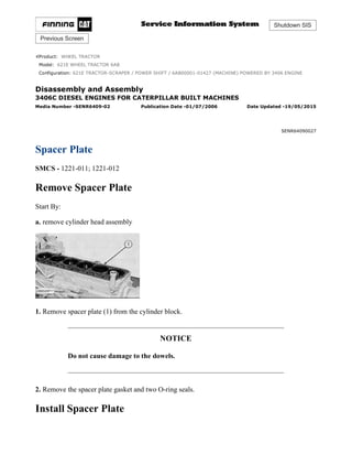
1. Remove spacer plate (1) from the cylinder block.
NOTICE
Do not cause damage to the dowels.
2. Remove the spacer plate gasket and two O-ring seals.
Install Spacer Plate
1/2(W)
w
2021/3/29
https://127.0.0.1/sisweb/sisweb/techdoc/techdoc_print_page.jsp?returnurl=/sisweb/sisw...
2. 1. Thoroughly clean the spacer plate and cylinder block surface. Install two O-ring seals (1) in the
cylinder block.
NOTICE
Both surfaces of the spacer plate, top of cylinder block and both sides
of the spacer plate gasket must be clean and dry. Gasket adhesives or
other substances must not be used on these surfaces.
2. Install a new gasket between the spacer plate and cylinder block. Put spacer plate (2) in position
on the cylinder block.
3. Check cylinder liner projection. See topic, "Install Cylinder Liners".
End By:
a. install cylinder head assembly
Copyright 1993 - 2021 Caterpillar Inc.
All Rights Reserved.
Private Network For SIS Licensees.
Mon Mar 29 18:10:49 UTC+0800 2021
2/2(W)
w
2021/3/29
https://127.0.0.1/sisweb/sisweb/techdoc/techdoc_print_page.jsp?returnurl=/sisweb/sisw...
3. Shutdown SIS
Previous Screen
Product: WHEEL TRACTOR
Model: 621E WHEEL TRACTOR 6AB
Configuration: 621E TRACTOR-SCRAPER / POWER SHIFT / 6AB00001-01427 (MACHINE) POWERED BY 3406 ENGINE
Disassembly and Assembly
3406C DIESEL ENGINES FOR CATERPILLAR BUILT MACHINES
Media Number -SENR6409-02 Publication Date -01/07/2006 Date Updated -19/05/2015
SENR64090028
Valves
SMCS - 1105-011; 1105-012
Remove Valves
Start By:
a. remove cylinder head assembly
1. Use Tool (A) to compress springs (1).
2. Remove the locks.
3. Remove Tool (A), the valve, the rotocoil, and the spring.
NOTE: If a valve can be used again, put identification on the valve for location at installation.
1/3(W)
w
2021/3/29
https://127.0.0.1/sisweb/sisweb/techdoc/techdoc_print_page.jsp?returnurl=/sisweb/sisw...
4. 4. Use Tool (B) to check spring force. The specifications for the spring are given in Specifications
Manual, SENR6470.
5. Do Steps 1 through 4 again for the remainder of the valves.
Install Valves
1. Put clean engine oil on the valve stem. Install washer (3), spring (2), rotocoil (1) and the valve.
2. Use Tool (A) to compress the spring.
3. Install locks (4) with the thick end up.
Locks can be thrown from valve when compressor is released, if they
are not in their correct position on the valve stem.
2/3(W)
w
2021/3/29
https://127.0.0.1/sisweb/sisweb/techdoc/techdoc_print_page.jsp?returnurl=/sisweb/sisw...
5. 4. Remove the compressor and hit the valve with a soft faced hammer to be sure locks are in their
correct position on the valve.
5. Do Steps 1 through 4 again for the remainder of the valves.
End By:
a. install cylinder assembly
Copyright 1993 - 2021 Caterpillar Inc.
All Rights Reserved.
Private Network For SIS Licensees.
Mon Mar 29 18:11:45 UTC+0800 2021
3/3(W)
w
2021/3/29
https://127.0.0.1/sisweb/sisweb/techdoc/techdoc_print_page.jsp?returnurl=/sisweb/sisw...
6. Shutdown SIS
Previous Screen
Product: WHEEL TRACTOR
Model: 621E WHEEL TRACTOR 6AB
Configuration: 621E TRACTOR-SCRAPER / POWER SHIFT / 6AB00001-01427 (MACHINE) POWERED BY 3406 ENGINE
Disassembly and Assembly
3406C DIESEL ENGINES FOR CATERPILLAR BUILT MACHINES
Media Number -SENR6409-02 Publication Date -01/07/2006 Date Updated -19/05/2015
SENR64090029
Valve Seat Inserts
SMCS - 1103-010
Remove & Install Valve Seat Inserts
Start By:
a. remove valves
1. Use Tool (A) to remove the valve seat inserts from the cylinder head.
2. Clean and remove any burrs from the valve seat bores.
NOTE: For reconditioning information of the cylinder head, see Service Training Meeting Guide,
SESV1202.
NOTE: The following steps are for the installation of the valve seat inserts.
1/2(W)
w
2021/3/29
https://127.0.0.1/sisweb/sisweb/techdoc/techdoc_print_page.jsp?returnurl=/sisweb/sisw...
7. 3. Lower the temperature of the new valve seat inserts. Use Tool (B) to install the new valve seat
inserts in the cylinder head.
End By:
a. install valves
Copyright 1993 - 2021 Caterpillar Inc.
All Rights Reserved.
Private Network For SIS Licensees.
Mon Mar 29 18:12:40 UTC+0800 2021
2/2(W)
w
2021/3/29
https://127.0.0.1/sisweb/sisweb/techdoc/techdoc_print_page.jsp?returnurl=/sisweb/sisw...
8. Shutdown SIS
Previous Screen
Product: WHEEL TRACTOR
Model: 621E WHEEL TRACTOR 6AB
Configuration: 621E TRACTOR-SCRAPER / POWER SHIFT / 6AB00001-01427 (MACHINE) POWERED BY 3406 ENGINE
Disassembly and Assembly
3406C DIESEL ENGINES FOR CATERPILLAR BUILT MACHINES
Media Number -SENR6409-02 Publication Date -01/07/2006 Date Updated -19/05/2015
SENR64090030
Bridge Dowels
SMCS - 1121-011; 1121-012
Remove Bridge Dowels
Start By:
a. remove valves
1. Use Tool (A) to remove bridge dowel (1).
Install Bridge Dowels
1/2(W)
w
2021/3/29
https://127.0.0.1/sisweb/sisweb/techdoc/techdoc_print_page.jsp?returnurl=/sisweb/sisw...
9. 1. Use Tool (A) to install the bridge dowel.
End By:
a. install valves
Copyright 1993 - 2021 Caterpillar Inc.
All Rights Reserved.
Private Network For SIS Licensees.
Mon Mar 29 18:13:36 UTC+0800 2021
2/2(W)
w
2021/3/29
https://127.0.0.1/sisweb/sisweb/techdoc/techdoc_print_page.jsp?returnurl=/sisweb/sisw...
10. Shutdown SIS
Previous Screen
Product: WHEEL TRACTOR
Model: 621E WHEEL TRACTOR 6AB
Configuration: 621E TRACTOR-SCRAPER / POWER SHIFT / 6AB00001-01427 (MACHINE) POWERED BY 3406 ENGINE
Disassembly and Assembly
3406C DIESEL ENGINES FOR CATERPILLAR BUILT MACHINES
Media Number -SENR6409-02 Publication Date -01/07/2006 Date Updated -19/05/2015
SENR64090031
Valve Guides
SMCS - 1104-011; 1104-012
Remove Valve Guides
Start By:
a. remove valves
1. Use Tool (A) to remove the valve guides.
Install Valve Guides
1/2(W)
w
2021/3/29
https://127.0.0.1/sisweb/sisweb/techdoc/techdoc_print_page.jsp?returnurl=/sisweb/sisw...
11. 1. Put clean engine oil on the outside of the valve guide.
2. Use Tool (A) to install the valve guides.
3. After installation, the inside diameter of the valve guide must be 9.487 ± 0.025 mm (.3735
± .0010 in). The maximum diameter of used guides is 8.538 mm (.3361 in).
End By:
a. install valves
Copyright 1993 - 2021 Caterpillar Inc.
All Rights Reserved.
Private Network For SIS Licensees.
Mon Mar 29 18:14:32 UTC+0800 2021
2/2(W)
w
2021/3/29
https://127.0.0.1/sisweb/sisweb/techdoc/techdoc_print_page.jsp?returnurl=/sisweb/sisw...
12. Shutdown SIS
Previous Screen
Product: WHEEL TRACTOR
Model: 621E WHEEL TRACTOR 6AB
Configuration: 621E TRACTOR-SCRAPER / POWER SHIFT / 6AB00001-01427 (MACHINE) POWERED BY 3406 ENGINE
Disassembly and Assembly
3406C DIESEL ENGINES FOR CATERPILLAR BUILT MACHINES
Media Number -SENR6409-02 Publication Date -01/07/2006 Date Updated -19/05/2015
SENR64090032
Oil Pan & Plate
SMCS - 1302-011; 1302-012
Remove Oil Pan & Plate
Typical Example
1. Drain the oil from the engine into a suitable container for storage or disposal.
2. Remove the lower clamp and bracket that hold the breather tube to the cylinder block and oil
pan.
3. Remove all but four of the bolts (1) that hold the oil pan to the cylinder block.
Use two persons to hold the oil pan in position while the last four bolts
are removed.
4. Remove the oil pan (2). Weight of the oil pan is 57 kg (126 lb).
1/2(W)
w
2021/3/29
https://127.0.0.1/sisweb/sisweb/techdoc/techdoc_print_page.jsp?returnurl=/sisweb/sisw...
13. 5. Remove suction bell (3). Remove suction bell and tube (4). Remove oil supply tube (5).
Remove plate (6).
Install Oil Pan & Plate
1. Put plate (1) in position on the cylinder block. Put suction bell and tube (2) in position on the oil
pump and cylinder block. Install the bolts that hold it.
2. Install oil supply tube (4).
3. Install the suction bell (3).
4. Install two 3/8 in 16 NC Guide Pins 6 in long in the cylinder block. Put the oil pan (5) in
position on the cylinder block. Install all but two of the bolts that hold it. Remove the two guide
pins. Install the last two bolts.
5. Fill the engine with oil to the correct level. See the Operation & Maintenance Manual.
Copyright 1993 - 2021 Caterpillar Inc.
All Rights Reserved.
Private Network For SIS Licensees.
Mon Mar 29 18:15:28 UTC+0800 2021
2/2(W)
w
2021/3/29
https://127.0.0.1/sisweb/sisweb/techdoc/techdoc_print_page.jsp?returnurl=/sisweb/sisw...
14. Shutdown SIS
Previous Screen
Product: WHEEL TRACTOR
Model: 621E WHEEL TRACTOR 6AB
Configuration: 621E TRACTOR-SCRAPER / POWER SHIFT / 6AB00001-01427 (MACHINE) POWERED BY 3406 ENGINE
Disassembly and Assembly
3406C DIESEL ENGINES FOR CATERPILLAR BUILT MACHINES
Media Number -SENR6409-02 Publication Date -01/07/2006 Date Updated -19/05/2015
SENR64090033
Oil Pump
SMCS - 1304-016; 1304-010; 1304-015
Remove & Install Oil Pump
Start By:
a. remove oil pan
1. Remove oil supply tube (1) and suction bell and tube (2).
2. Remove bolts (3) that hold the oil pump to the cylinder block and remove oil pump (4).
3. To install, put oil pump (4) in position on the cylinder block. Install the bolts that hold the oil
pump to the cylinder block.
4. Put clean engine oil on the O-ring seals of the tubes.
1/4(W)
w
2021/3/29
https://127.0.0.1/sisweb/sisweb/techdoc/techdoc_print_page.jsp?returnurl=/sisweb/sisw...
15. 5. Install oil supply tube (1), suction bell and tube (2).
End By:
a. install oil pan
Disassemble Oil Pump
Start By:
a. remove oil pump
1. Remove the bolt and washer that hold the gear on the shaft.
2. Use Tool (A) and remove drive gear (1) from the shaft. Remove the key from the shaft.
3. Remove retainer (3) for the bypass valve. Remove the spring and the bypass valve.
4. Remove cover (2) from the pump body.
2/4(W)
w
2021/3/29
https://127.0.0.1/sisweb/sisweb/techdoc/techdoc_print_page.jsp?returnurl=/sisweb/sisw...
16. 5. Use Tool (B) and remove the bearings from the cover.
6. Remove gears (5) from pump body (4).
7. Use Tool (B) and remove the bearings from pump body (4).
Assemble Oil Pump
1. Use Tool (B) to install the bearings in the pump body. Install the bearings so the joint in the
bearings is 30 ± 15 degrees from the center line of the oil pump outlet passage (2).
3/4(W)
w
2021/3/29
https://127.0.0.1/sisweb/sisweb/techdoc/techdoc_print_page.jsp?returnurl=/sisweb/sisw...
17. 2. Install idler gear and drive gear (5) in the oil pump body (4). Put clean engine oil on the
bearings and the gears.
3. Use Tool (A) and install the bearings in cover (2). Install the bearings so the joint of the bearing
bores toward oil pump outlet passage (6).
4. Install bypass valve (7), spring (8) and the retainer.
5. Install the key on the shaft.
6. Install gear (1) on the shaft. Install the washer and bolt that hold the gear on the shaft. Be sure
the pump turns freely after assembly.
End By:
a. install oil pump
Copyright 1993 - 2021 Caterpillar Inc.
All Rights Reserved.
Private Network For SIS Licensees.
Mon Mar 29 18:16:24 UTC+0800 2021
4/4(W)
w
2021/3/29
https://127.0.0.1/sisweb/sisweb/techdoc/techdoc_print_page.jsp?returnurl=/sisweb/sisw...
18. Shutdown SIS
Previous Screen
Product: WHEEL TRACTOR
Model: 621E WHEEL TRACTOR 6AB
Configuration: 621E TRACTOR-SCRAPER / POWER SHIFT / 6AB00001-01427 (MACHINE) POWERED BY 3406 ENGINE
Disassembly and Assembly
3406C DIESEL ENGINES FOR CATERPILLAR BUILT MACHINES
Media Number -SENR6409-02 Publication Date -01/07/2006 Date Updated -19/05/2015
SENR64090034
Piston Cooling Tubes
SMCS - 1307-010
Remove & Install Piston Cooling Tubes
Start By:
a. remove oil pump
NOTE: The piston and connecting rod were removed for better illustration.
1. Remove bolts (1). Remove piston cooling tubes (2) from the engine. Use Tool (A) to turn the
crankshaft in a clockwise direction (as seen from the front of the engine) to get access to all of the
piston cooling tubes.
NOTE: The following steps are for the installation of the piston cooling tubes.
2. Check the alignment of the piston cooling tubes with Tool (B). See Use Of 5P8709 Tool Group
for Alignment Of Piston Cooling Jets, SMHS7267 for the correct alignment procedure.
1/2(W)
w
2021/3/29
https://127.0.0.1/sisweb/sisweb/techdoc/techdoc_print_page.jsp?returnurl=/sisweb/sisw...
19. 3. Install piston cooling tubes (2) on the engine. Use Tool (A) to turn the crankshaft clockwise (as
seen from the front of the engine) to get access for the installation of the piston cooling tubes.
End By:
a. install oil pump
Copyright 1993 - 2021 Caterpillar Inc.
All Rights Reserved.
Private Network For SIS Licensees.
Mon Mar 29 18:17:19 UTC+0800 2021
2/2(W)
w
2021/3/29
https://127.0.0.1/sisweb/sisweb/techdoc/techdoc_print_page.jsp?returnurl=/sisweb/sisw...
20. Shutdown SIS
Previous Screen
Product: WHEEL TRACTOR
Model: 621E WHEEL TRACTOR 6AB
Configuration: 621E TRACTOR-SCRAPER / POWER SHIFT / 6AB00001-01427 (MACHINE) POWERED BY 3406 ENGINE
Disassembly and Assembly
3406C DIESEL ENGINES FOR CATERPILLAR BUILT MACHINES
Media Number -SENR6409-02 Publication Date -01/07/2006 Date Updated -19/05/2015
SENR64090035
Pistons & Connecting Rod Assemblies
SMCS - 1225-017; 1225-011; 1225-012
Remove Pistons & Connecting Rod Assemblies
Start By:
a. remove cylinder head assembly
b. remove oil pump
c. remove piston cooling tubes
1. Remove the carbon ridge from the top inside surface of the cylinder liners.
2. Turn the crankshaft until two pistons are at bottom center.
3. Remove bolts (1) and the bearing caps. Push the rods and pistons up until the rings are out of
the cylinder liners.
1/5(W)
w
2021/3/29
https://127.0.0.1/sisweb/sisweb/techdoc/techdoc_print_page.jsp?returnurl=/sisweb/sisw...
21. 4. Remove pistons (2) and connecting rods from the cylinder liners.
5. Do Steps 1 through 4 for the remainder of the pistons and connecting rods.
Install Pistons & Connecting Rod Assemblies
1. Put clean engine oil on piston rings, connecting rod bearings and cylinder liners.
2. Use Tool (A), and install piston (2) and the connecting rod in the cylinder liner.
3. Install the bearing cap on the connecting rod with the number on the side of the bearing cap on
the same side and same number as on the connecting rod.
4. Put 2P2506 Thread Lubricant on the threads of the bolts. Install the nuts, and tighten them to
a torque of 90 ± 8 N·m (67 ± 6 lb ft). Put a mark on the nuts and cap, and tighten the nuts an extra
90 ± 5 degrees.
5. Do Steps 1 through 4 for the remainder of the pistons and connecting rods.
End By:
a. install piston cooling tubes
b. install oil pump
c. install cylinder head assembly
2/5(W)
w
2021/3/29
https://127.0.0.1/sisweb/sisweb/techdoc/techdoc_print_page.jsp?returnurl=/sisweb/sisw...
22. Disassemble & Assemble Pistons & Connecting Rod
Assemblies
Start By:
a. remove pistons and connecting rod assemblies
1. Remove bearings (3) from the connecting rod and connecting rod cap.
2. Remove retainer ring (1) with Tool (A).
3. Remove pin (2) and connecting rod (4) from the piston.
4. Remove piston rings (5) from the piston with Tool (B). Clean the piston ring grooves on the
pistons with an acceptable ring groove cleaning tool.
3/5(W)
w
2021/3/29
https://127.0.0.1/sisweb/sisweb/techdoc/techdoc_print_page.jsp?returnurl=/sisweb/sisw...
23. NOTE: See, Use Of Piston Bearing Removal And Installation Tools, Special Instructions,
SMHS7295.
5. Heat connecting rod (4) in an oven to a temperature of 177° to 260°C (350° to 500° F). Never
use a direct flame to heat a connecting rod.
6. Put connecting rod (4) in position on the base plate of Tool (C). Put a new rod pin bearing (6)
on the adapter part of Tool (C).
NOTE: The old bearing is pushed out by Tool (C) as the new bearing is installed.
7. Use Tool (C) to push the new bearing into the connecting rod until the push adapter of Tool (C)
makes full contact with the connecting rod surface.
8. Use a pin boring machine to make the rod pin bearing the correct size. The bore in the new rod
pin bearing must be 50.830 ± 0.008 mm (2.0012 ± .0003 in).
9. Check the clearance between the ends of the piston rings. See the topic, "Pistons & Rings" in
Specifications Manual, SENR6470.
10. Install the oil ring spring in the oil ring groove of the piston.
NOTE: The oil ring is to be installed over the spring with the oil ring end gap 180° from the oil
ring spring joint.
11. Install the oil ring on the piston with tool (B).
12. Install the second (intermediate) piston ring with the side that has the identification "UP-2"
toward the top of the piston. Use Tool (B) to install the ring.
13. Install the first (top) piston ring with the side that has the identification "UP-1" toward the top
of the piston. Use Tool (B) to install the ring.
NOTE: After the installation of all three piston rings, put the piston rings in position so the end
gaps are 120 degrees apart.
14. Put the piston in position on connecting rod (4). Put clean engine oil on pin (2), and install the
pin. Install retainer rings (1) with Tool (A). Make sure the retainer rings are in the grooves of the
piston.
15. Install bearings (3) in the connecting rod and connecting rod cap.
4/5(W)
w
2021/3/29
https://127.0.0.1/sisweb/sisweb/techdoc/techdoc_print_page.jsp?returnurl=/sisweb/sisw...
24. NOTE: Be sure the tabs in back of the bearings are in tab slots of the connecting rod and
connecting rod cap.
End By:
a. install pistons and connecting rod assemblies
Copyright 1993 - 2021 Caterpillar Inc.
All Rights Reserved.
Private Network For SIS Licensees.
Mon Mar 29 18:18:15 UTC+0800 2021
5/5(W)
w
2021/3/29
https://127.0.0.1/sisweb/sisweb/techdoc/techdoc_print_page.jsp?returnurl=/sisweb/sisw...
25. Shutdown SIS
Previous Screen
Product: WHEEL TRACTOR
Model: 621E WHEEL TRACTOR 6AB
Configuration: 621E TRACTOR-SCRAPER / POWER SHIFT / 6AB00001-01427 (MACHINE) POWERED BY 3406 ENGINE
Disassembly and Assembly
3406C DIESEL ENGINES FOR CATERPILLAR BUILT MACHINES
Media Number -SENR6409-02 Publication Date -01/07/2006 Date Updated -19/05/2015
SENR64090036
Cylinder Liners
SMCS - 1216-010
Remove & Install Cylinder Liners
Start By:
a. remove pistons and connecting rod assemblies
1. Put covers on the journals of the crankshaft for protection from dirt or water.
2. Remove the cylinder liners with Tool (A) as shown.
NOTE: The Caterpillar pack pulling tools can be used to remove the cylinder liner, piston and
connecting rod as a unit. For more detail, see Special Instruction, SEHS8554.
1/2(W)
w
2021/3/29
https://127.0.0.1/sisweb/sisweb/techdoc/techdoc_print_page.jsp?returnurl=/sisweb/sisw...
26. 3. To install, clean the cylinder liners and liner bores in the cylinder block.
4. Install cylinder liners (1) in the block without the O-ring seals or filler band.
5. To check the cylinder liner projection, see the topic, "Cylinder Liner Projection" in Systems
Operations Testing & Adjusting Manual SENR6471.
6. Remove the liner. Install new O-ring seals on the liners.
7. Put liquid soap on the O-ring seals and on the cylinder bores. Put the filler band in SAE 30W
Oil, then immediately install the filler band on the cylinder liner. Immediately install the cylinder
liner in the cylinder block with Tool (B) before expansion of the band.
End By:
a. install pistons and connecting rod assemblies
Copyright 1993 - 2021 Caterpillar Inc.
All Rights Reserved.
Private Network For SIS Licensees.
Mon Mar 29 18:19:11 UTC+0800 2021
2/2(W)
w
2021/3/29
https://127.0.0.1/sisweb/sisweb/techdoc/techdoc_print_page.jsp?returnurl=/sisweb/sisw...
27. Shutdown SIS
Previous Screen
Product: WHEEL TRACTOR
Model: 621E WHEEL TRACTOR 6AB
Configuration: 621E TRACTOR-SCRAPER / POWER SHIFT / 6AB00001-01427 (MACHINE) POWERED BY 3406 ENGINE
Disassembly and Assembly
3406C DIESEL ENGINES FOR CATERPILLAR BUILT MACHINES
Media Number -SENR6409-02 Publication Date -01/07/2006 Date Updated -19/05/2015
SENR64090037
Timing Gear Cover
SMCS - 1166-010
Remove & Install Timing Gear Cover
Start By:
a. remove water pump
b. remove governor and fuel pump drive
c. remove oil pan
d. remove crankshaft front seal and wear sleeve
e. remove engine front support
1. Remove governor and fuel pump drive covers to timing gear cover bolts (1).
2. Remove two fuel injection pump housing to timing gear cover bolts (2) and two plates to cover
bolts (3).
1/2(W)
w
2021/3/29
https://127.0.0.1/sisweb/sisweb/techdoc/techdoc_print_page.jsp?returnurl=/sisweb/sisw...
28. Please write to us.
Our email:
aservicemanualpdf@yahoo.com
Please go to the homepage
to get the full manual, or
other brand PDF manuals.
Home Site:
aservicemanualpdf.com
29. Thank you very much for
your reading. Please Click
Here. Then Get COMPLETE
MANUAL. NO WAITING
NOTE:
If there is no response to
click on the link above,
please download the PDF
document first and then
click on it.
GET MORE OTHER MANUALS https://www.aservicemanualpdf.com/
GET MORE OTHER MANUALS https://www.aservicemanualpdf.com/
30. 3. Remove the five timing gear covers to cylinder block bolts and remove timing gear cover (4).
4. To install, be sure that O-ring seal (5) is in position in the timing gear plate as shown.
5. Put a new gasket in position and install timing gear cover (4) over the two dowel pins in the
cylinder block.
6. Install the bolts that hold the timing gear cover to the cylinder block. Cut the cover gasket to
make it even with the surface of the cylinder block and the bottom of the timing gear cover.
7. Install the bolts that hold the governor and fuel pump drive cover to the timing gear cover.
Install the fuel injection pump housing to timing gear cover bolts and the two plates to cover bolts.
End By:
a. install engine front support
b. install crankshaft front seal and wear sleeve
c. install oil pan
d. install governor and fuel pump drive
e. install water pump
Copyright 1993 - 2021 Caterpillar Inc.
All Rights Reserved.
Private Network For SIS Licensees.
Mon Mar 29 18:20:07 UTC+0800 2021
2/2(W)
w
2021/3/29
https://127.0.0.1/sisweb/sisweb/techdoc/techdoc_print_page.jsp?returnurl=/sisweb/sisw...
31. Shutdown SIS
Previous Screen
Product: WHEEL TRACTOR
Model: 621E WHEEL TRACTOR 6AB
Configuration: 621E TRACTOR-SCRAPER / POWER SHIFT / 6AB00001-01427 (MACHINE) POWERED BY 3406 ENGINE
Disassembly and Assembly
3406C DIESEL ENGINES FOR CATERPILLAR BUILT MACHINES
Media Number -SENR6409-02 Publication Date -01/07/2006 Date Updated -19/05/2015
SENR64090038
Timing Gears & Plate
SMCS - 1162-010; 1206
Remove & Install Timing Gears & Plate
Start By:
a. remove timing gear cover
b. remove fuel injection pump housing and governor
1. Remove four bolts (2), plate (3) and idler gear (1).
1/3(W)
w
2021/3/29
https://127.0.0.1/sisweb/sisweb/techdoc/techdoc_print_page.jsp?returnurl=/sisweb/sisw...
32. 2. If the camshaft is not going to be removed, use Tool (A) to remove camshaft gear (4).
NOTICE
Do not turn the crankshaft with the camshaft gear removed. Damage
can be caused to the pistons and valves or both.
3. Remove bolts (5) that hold timing gear plate (6) to the cylinder block.
4. Remove timing gear plate (6).
5. Use Tool (B) to remove the bearing from the idler gear.
NOTE: The following steps are for the installation of the timing gears and plate.
6. Install a new gasket on the timing gear plate.
7. Put timing gear plate (6) in position on the cylinder block and install the bolts that hold the
timing gear plate to the cylinder block.
8. Heat camshaft gear (4) to a maximum temperature of 205° C (400° F) for no longer than three
hours and install it on the camshaft.
2/3(W)
w
2021/3/29
https://127.0.0.1/sisweb/sisweb/techdoc/techdoc_print_page.jsp?returnurl=/sisweb/sisw...