This document provides instructions for assembling and disassembling the transfer gears of a 631G wheel scraper. The assembly procedure involves 18 steps including installing bearings and seals into bearing cages, installing gears and bearing cages into the transfer gear case housing, and torquing bolts to specified values. Tools required include link brackets, pullers, drivers, and dial indicators. Cleanliness is emphasized to prevent contamination of hydraulic components.
Core technology of Hyundai Motor Group's EV platform 'E-GMP'Hyundai Motor Group
What’s the force behind Hyundai Motor Group's EV performance and quality?
Maximized driving performance and quick charging time through high-density battery pack and fast charging technology and applicable to various vehicle types!
Discover more about Hyundai Motor Group’s EV platform ‘E-GMP’!
Comprehensive program for Agricultural Finance, the Automotive Sector, and Empowerment . We will define the full scope and provide a detailed two-week plan for identifying strategic partners in each area within Limpopo, including target areas.:
1. Agricultural : Supporting Primary and Secondary Agriculture
• Scope: Provide support solutions to enhance agricultural productivity and sustainability.
• Target Areas: Polokwane, Tzaneen, Thohoyandou, Makhado, and Giyani.
2. Automotive Sector: Partnerships with Mechanics and Panel Beater Shops
• Scope: Develop collaborations with automotive service providers to improve service quality and business operations.
• Target Areas: Polokwane, Lephalale, Mokopane, Phalaborwa, and Bela-Bela.
3. Empowerment : Focusing on Women Empowerment
• Scope: Provide business support support and training to women-owned businesses, promoting economic inclusion.
• Target Areas: Polokwane, Thohoyandou, Musina, Burgersfort, and Louis Trichardt.
We will also prioritize Industrial Economic Zone areas and their priorities.
Sign up on https://profilesmes.online/welcome/
To be eligible:
1. You must have a registered business and operate in Limpopo
2. Generate revenue
3. Sectors : Agriculture ( primary and secondary) and Automative
Women and Youth are encouraged to apply even if you don't fall in those sectors.
What Does the PARKTRONIC Inoperative, See Owner's Manual Message Mean for You...Autohaus Service and Sales
Learn what "PARKTRONIC Inoperative, See Owner's Manual" means for your Mercedes-Benz. This message indicates a malfunction in the parking assistance system, potentially due to sensor issues or electrical faults. Prompt attention is crucial to ensure safety and functionality. Follow steps outlined for diagnosis and repair in the owner's manual.
In this presentation, we have discussed a very important feature of BMW X5 cars… the Comfort Access. Things that can significantly limit its functionality. And things that you can try to restore the functionality of such a convenient feature of your vehicle.
"Trans Failsafe Prog" on your BMW X5 indicates potential transmission issues requiring immediate action. This safety feature activates in response to abnormalities like low fluid levels, leaks, faulty sensors, electrical or mechanical failures, and overheating.
𝘼𝙣𝙩𝙞𝙦𝙪𝙚 𝙋𝙡𝙖𝙨𝙩𝙞𝙘 𝙏𝙧𝙖𝙙𝙚𝙧𝙨 𝙞𝙨 𝙫𝙚𝙧𝙮 𝙛𝙖𝙢𝙤𝙪𝙨 𝙛𝙤𝙧 𝙢𝙖𝙣𝙪𝙛𝙖𝙘𝙩𝙪𝙧𝙞𝙣𝙜 𝙩𝙝𝙚𝙞𝙧 𝙥𝙧𝙤𝙙𝙪𝙘𝙩𝙨. 𝙒𝙚 𝙝𝙖𝙫𝙚 𝙖𝙡𝙡 𝙩𝙝𝙚 𝙥𝙡𝙖𝙨𝙩𝙞𝙘 𝙜𝙧𝙖𝙣𝙪𝙡𝙚𝙨 𝙪𝙨𝙚𝙙 𝙞𝙣 𝙖𝙪𝙩𝙤𝙢𝙤𝙩𝙞𝙫𝙚 𝙖𝙣𝙙 𝙖𝙪𝙩𝙤 𝙥𝙖𝙧𝙩𝙨 𝙖𝙣𝙙 𝙖𝙡𝙡 𝙩𝙝𝙚 𝙛𝙖𝙢𝙤𝙪𝙨 𝙘𝙤𝙢𝙥𝙖𝙣𝙞𝙚𝙨 𝙗𝙪𝙮 𝙩𝙝𝙚 𝙜𝙧𝙖𝙣𝙪𝙡𝙚𝙨 𝙛𝙧𝙤𝙢 𝙪𝙨.
Over the 10 years, we have gained a strong foothold in the market due to our range's high quality, competitive prices, and time-lined delivery schedules.
5 Warning Signs Your BMW's Intelligent Battery Sensor Needs AttentionBertini's German Motors
IBS monitors and manages your BMW’s battery performance. If it malfunctions, you will have to deal with an array of electrical issues in your vehicle. Recognize warning signs like dimming headlights, frequent battery replacements, and electrical malfunctions to address potential IBS issues promptly.
Why Is Your BMW X3 Hood Not Responding To Release CommandsDart Auto
Experiencing difficulty opening your BMW X3's hood? This guide explores potential issues like mechanical obstruction, hood release mechanism failure, electrical problems, and emergency release malfunctions. Troubleshooting tips include basic checks, clearing obstructions, applying pressure, and using the emergency release.
Symptoms like intermittent starting and key recognition errors signal potential problems with your Mercedes’ EIS. Use diagnostic steps like error code checks and spare key tests. Professional diagnosis and solutions like EIS replacement ensure safe driving. Consult a qualified technician for accurate diagnosis and repair.
What Does the Active Steering Malfunction Warning Mean for Your BMWTanner Motors
Discover the reasons why your BMW’s Active Steering malfunction warning might come on. From electrical glitches to mechanical failures and software anomalies, addressing these promptly with professional inspection and maintenance ensures continued safety and performance on the road, maintaining the integrity of your driving experience.
What Exactly Is The Common Rail Direct Injection System & How Does It WorkMotor Cars International
Learn about Common Rail Direct Injection (CRDi) - the revolutionary technology that has made diesel engines more efficient. Explore its workings, advantages like enhanced fuel efficiency and increased power output, along with drawbacks such as complexity and higher initial cost. Compare CRDi with traditional diesel engines and discover why it's the preferred choice for modern engines.
Things to remember while upgrading the brakes of your carjennifermiller8137
Upgrading the brakes of your car? Keep these things in mind before doing so. Additionally, start using an OBD 2 GPS tracker so that you never miss a vehicle maintenance appointment. On top of this, a car GPS tracker will also let you master good driving habits that will let you increase the operational life of your car’s brakes.
Things to remember while upgrading the brakes of your car
Caterpillar Cat 631G WHEEL SCRAPER (Prefix DEM) Service Repair Manual (DEM00001 and up).pdf
1. Shutdown SIS
Previous Screen
Product: WHEEL SCRAPER
Model: 631G WHEEL SCRAPER DEM
Configuration: 631G Wheel Scraper DEM00001-UP (MACHINE)
Disassembly and Assembly
631G Wheel Tractor-Scraper Power Train
Media Number -RENR8604-01 Publication Date -01/08/2010 Date Updated -09/08/2010
i06636123
Torque Converter - Assemble
SMCS - 3101-016
Assembly Procedure
Table 1
Required Tools
Tool Part Number Part Description Qty
A 2P-8312 Retaining Ring Pliers 1
B 1P-0510 Driver Group 1
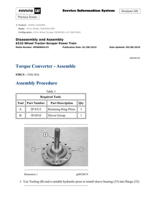
Illustration 1 g00528674
1. Use Tooling (B) and a suitable hydraulic press to install sleeve bearing (33) into flange (32).
1/7(W)
w
2021/6/18
https://127.0.0.1/sisweb/sisweb/techdoc/techdoc_print_page.jsp?returnurl=/sisweb/sisw...
2. Illustration 2 g00528612
2. Position flange (32) and install bolts (31) onto housing (9). Tighten bolts (31) to a torque of
120 ± 15 N·m (89 ± 11 lb ft).
Illustration 3 g00525322
3. Install thrust bearing (29) and thrust race (30) into housing (9).
Illustration 4 g00525321
4. Install turbine (23) and clamp ring (28) onto hub (3).
2/7(W)
w
2021/6/18
https://127.0.0.1/sisweb/sisweb/techdoc/techdoc_print_page.jsp?returnurl=/sisweb/sisw...
3. Illustration 5 g00525320
5. Install bolts (27) into turbine (23). Tighten bolts (27) to a torque of 50 ± 7 N·m
(37 ± 5 lb ft). Install thrust race (26) onto hub (3).
Illustration 6 g01102582
6. Install thrust race (25) and thrust bearing (24) onto hub (3).
Illustration 7 g00525315
7. Install turbine (23) and hub (3) as a unit into housing (9).
3/7(W)
w
2021/6/18
https://127.0.0.1/sisweb/sisweb/techdoc/techdoc_print_page.jsp?returnurl=/sisweb/sisw...
4. Illustration 8 g00528953
8. Use Tooling (B) and a suitable press to install sleeve bearing (22) into carrier assembly (12).
Install thrust bearing (21) onto carrier assembly (12).
Illustration 9 g01110492
9. Install side plate (20) to stator (13). Use Tooling (A) to install retaining ring (19) to stator
(13).
Illustration 10 g01102579
10. Use Tooling (B) and a suitable hydraulic press to install freewheel cam (18) into stator (13).
4/7(W)
w
2021/6/18
https://127.0.0.1/sisweb/sisweb/techdoc/techdoc_print_page.jsp?returnurl=/sisweb/sisw...
5. 11. Install stator (13) to carrier assembly (12). Install freewheel springs (16) and freewheel
rollers (17) to freewheel cam (18). Always install new freewheel springs (16) and freewheel
rollers (17). Install freewheel springs (16) with the maximum number of loops in freewheel
springs (16) to the outside of freewheel cam (18). Stator (13) should turn freely in the
clockwise direction. Stator (13) should not turn freely in the counterclockwise direction.
Illustration 11 g01110494
12. Install thrust race (15) to stator (13). Use Tooling (A) to install retaining ring (14) onto
stator (13).
Illustration 12 g00525308
13. Install carrier assembly (12) and stator (13) as a unit into housing (9).
5/7(W)
w
2021/6/18
https://127.0.0.1/sisweb/sisweb/techdoc/techdoc_print_page.jsp?returnurl=/sisweb/sisw...
6. Illustration 13 g01108447
14. Install thrust bearing (11) and seal ring (12A) onto carrier assembly (12).
Illustration 14 g00525305
15. Install impeller hub (8) to impeller (5). Install thrust race (10) onto impeller (5).
Illustration 15 g01102576
16. Install clamp plate (7) and bolts (6) onto impeller hub (8). Tighten bolts (6) to a torque of
50 ± 7 N·m (37 ± 5 lb ft).
17. Install bolts (4) into impeller (5). Tighten bolts (4) to a torque of 50 ± 7 N·m (37 ± 5 lb ft).
6/7(W)
w
2021/6/18
https://127.0.0.1/sisweb/sisweb/techdoc/techdoc_print_page.jsp?returnurl=/sisweb/sisw...
7. Illustration 16 g00525299
18. Use Tooling (B) and a suitable press to install the sleeve bearing in carriage support
assembly (2). Install the sleeve bearing until the sleeve bearing is flush with the outside
machined surface of carriage support assembly (2).
19. Install carriage support assembly (2) onto hub (3). Use Tooling (A) to install retaining ring
(1) onto carriage support assembly (2).
End By:
a. Install the torque converter. Refer to Disassembly and Assembly, "Torque Converter -
Install".
Copyright 1993 - 2021 Caterpillar Inc.
All Rights Reserved.
Private Network For SIS Licensees.
Fri Jun 18 10:24:08 UTC+0800 2021
7/7(W)
w
2021/6/18
https://127.0.0.1/sisweb/sisweb/techdoc/techdoc_print_page.jsp?returnurl=/sisweb/sisw...
8. Shutdown SIS
Previous Screen
Product: WHEEL SCRAPER
Model: 631G WHEEL SCRAPER DEM
Configuration: 631G Wheel Scraper DEM00001-UP (MACHINE)
Disassembly and Assembly
631G Wheel Tractor-Scraper Power Train
Media Number -RENR8604-01 Publication Date -01/08/2010 Date Updated -09/08/2010
i02301155
Transfer Gears - Disassemble
SMCS - 3159-015
Disassembly Procedure
Table 1
Required Tools
Tool Part Number Part Description Qty
A 138-7575 Link Bracket 1
B
8B-7548 Push-Puller Tool Gp 1
8B-7551 Bearing Puller Gp 1
1P-0498 Drive Plate 1
C
5P-4170 Step Plate 1
1P-2321 Combination Puller 1
D
8B-7554 Bearing Cup Puller Gp 1
5P-4170 Step Plate 1
1P-0518 Drive Plate 1
E
8B-7560 Step Plate 1
5F-7345 Screw 1
8B-7554 Bearing Cup Puller Gp 1
F -
Bolts
3/8" - 16 NC by 3 inch
3
Start By:
1/8(W)
w
2021/6/18
https://127.0.0.1/sisweb/sisweb/techdoc/techdoc_print_page.jsp?returnurl=/sisweb/sisw...
9. a. Remove the transfer gear case. Refer to Disassembly and Assembly, "Transfer Gears -
Remove".
b. Remove the transmission oil filter base. Refer to Disassembly and Assembly, "Transmission
Oil Filter Base - Remove and Install".
c. Remove the transmission scavenge pump. Refer to Disassembly and Assembly,
"Transmission Scavenge Pump - Remove".
d. Remove the transmission oil pump. Refer to Disassembly and Assembly, "Transmission Oil
Pump - Remove".
NOTICE
Care must be taken to ensure that fluids are contained during
performance of inspection, maintenance, testing, adjusting, and repair
of the product. Be prepared to collect the fluid with suitable containers
before opening any compartment or disassembling any component
containing fluids.
Refer to Special Publication, NENG2500, "Dealer Service Tool
Catalog" for tools and supplies suitable to collect and contain fluids on
Cat®
products.
Dispose of all fluids according to local regulations and mandates.
NOTICE
Keep all parts clean from contaminants.
Contamination of the hydraulic system with foreign material will
reduce the service life of the hydraulic system components.
To prevent contaminants from entering the hydraulic system, always
plug or cap the lines, fittings, or hoses as they are disconnected. Cover
any disassembled components and clean them properly before
assembly.
Clean the hydraulic system properly after any major component
exchange or especially after a component failure, to remove any
contamination.
1. Put identification marks on components for installation purposes.
2/8(W)
w
2021/6/18
https://127.0.0.1/sisweb/sisweb/techdoc/techdoc_print_page.jsp?returnurl=/sisweb/sisw...
10. Illustration 1 g01048669
2. Remove the bolts that secure bearing cage (1) to the transfer gear case. Use Tooling (F) in
order to separate bearing cage (1) from the transfer gear case.
3. Remove bearing cage (1), shims (2), and pump drive gear (3) from the transfer gear case.
Illustration 2 g01102869
4. Remove the bolts that secure bearing cage (4) to the transfer gear case. Use Tooling (F) in
order to separate bearing cage (4) from the transfer gear case.
5. Remove bearing cage (4), shims (5), and gear (6) from the transfer gear case.
Illustration 3 g00529211
3/8(W)
w
2021/6/18
https://127.0.0.1/sisweb/sisweb/techdoc/techdoc_print_page.jsp?returnurl=/sisweb/sisw...
11. 6. Remove bearing cups (7) and (8) from the transfer gear case. Attach Tooling (A) and a
suitable lifting device onto the transfer gear case. The weight of the transfer gear case is
approximately 340 kg (750 lb). Turn over the transfer gear case. Remove Tooling (A).
Illustration 4 g01102873
7. Remove the bolts that secure bearing cage (9) to the transfer gear case. Use Tooling (F) in
order to separate bearing cage (9) from the transfer gear case.
8. Remove bearing cage (9), shims (10), and gear (11) from the transfer gear case.
Illustration 5 g00529214
9. Remove bearing cup (12) from the transfer gear case. Attach Tooling (A) and a suitable
lifting device onto the transfer gear case. Turn over the transfer gear case.
4/8(W)
w
2021/6/18
https://127.0.0.1/sisweb/sisweb/techdoc/techdoc_print_page.jsp?returnurl=/sisweb/sisw...
12. Illustration 6 g00529215
10. Remove bolts (13) that secure bearing cage (14) to the transfer gear case. If necessary, rotate
the gear until the three threaded holes are visible in bearing cage (14). Install Tooling (F)
through gear (15) and into bearing cage (14). Tighten Tooling (F) evenly until bearing cage
(14) and gear (15) separate from the transfer gear case. Remove bearing cage (14) and gear
(15) as a unit from the transfer gear case.
Illustration 7 g00529216
Illustration 8 g00529257
11. Remove retaining ring (16) from gear (15). Remove bearing (17) and bearing cage (14)
from gear (15).
5/8(W)
w
2021/6/18
https://127.0.0.1/sisweb/sisweb/techdoc/techdoc_print_page.jsp?returnurl=/sisweb/sisw...
13. Illustration 9 g01048544
12. Remove bearing (17) from bearing cage (14).
Illustration 10 g01048548
13. Remove bolts (19) and separate gear (20) from gear (11). Use Tooling (B) to remove
bearing cone (18) from gear (11). Repeat the procedure for the bearing cone on the opposite
side of the gear.
Illustration 11 g01048549
14. Use Tooling (C) to remove bearing cone (21) from gear (6). Repeat the procedure for the
bearing cone on the opposite side of gear (6).
6/8(W)
w
2021/6/18
https://127.0.0.1/sisweb/sisweb/techdoc/techdoc_print_page.jsp?returnurl=/sisweb/sisw...
14. Illustration 12 g01048550
15. Use Tooling (C) to remove bearing cone (22) from gear (3). Repeat the procedure for the
bearing cone on the opposite side of gear (3).
Illustration 13 g01048551
16. Use Tooling (D) to remove bearing cup (23) from bearing cage (4). Remove O-ring seal
(24) from bearing cage (4).
Illustration 14 g01048553
17. Remove bearing cup (25) from bearing cage (9).
7/8(W)
w
2021/6/18
https://127.0.0.1/sisweb/sisweb/techdoc/techdoc_print_page.jsp?returnurl=/sisweb/sisw...
15. Illustration 15 g01048552
18. Use Tooling (E) to remove bearing cup (26) from bearing cage (1). Remove O-ring seal (27)
from bearing cage (1).
Copyright 1993 - 2021 Caterpillar Inc.
All Rights Reserved.
Private Network For SIS Licensees.
Fri Jun 18 10:25:11 UTC+0800 2021
8/8(W)
w
2021/6/18
https://127.0.0.1/sisweb/sisweb/techdoc/techdoc_print_page.jsp?returnurl=/sisweb/sisw...
16. Shutdown SIS
Previous Screen
Product: WHEEL SCRAPER
Model: 631G WHEEL SCRAPER DEM
Configuration: 631G Wheel Scraper DEM00001-UP (MACHINE)
Disassembly and Assembly
631G Wheel Tractor-Scraper Power Train
Media Number -RENR8604-01 Publication Date -01/08/2010 Date Updated -09/08/2010
i07232119
Transfer Gears - Assemble
SMCS - 3159-016
Assembly Procedure
Table 1
Required Tools
Tool Part Number Part Description Qty
A 138-7575 Link Bracket 1
G 1P-0510 Driver Group 1
H 8T-5096 Dial Indicator 1
NOTICE
Keep all parts clean from contaminants.
Contamination of the hydraulic system with foreign material will
reduce the service life of the hydraulic system components.
To prevent contaminants from entering the hydraulic system, always
plug or cap the lines, fittings, or hoses as they are disconnected. Cover
any disassembled components and clean them properly before
assembly.
Clean the hydraulic system properly after any major component
exchange or especially after a component failure, to remove any
contamination.
1/9(W)
w
2021/6/18
https://127.0.0.1/sisweb/sisweb/techdoc/techdoc_print_page.jsp?returnurl=/sisweb/sisw...
17. 1. Clean all parts and inspect all parts. If any parts are worn or damaged, use new parts for
replacement.
2. Lubricate O-ring seals with the lubricant that is being sealed.
Illustration 1 g01048544
3. Install bearing (17) into bearing cage (14).
Illustration 2 g00529216
4. Use Tooling (G) to install bearing (17) and bearing cage (14) to gear (15). Install bearing
(17) and bearing cage (14) until the retaining ring groove is visible. Install retaining ring
(16) to gear (15).
2/9(W)
w
2021/6/18
https://127.0.0.1/sisweb/sisweb/techdoc/techdoc_print_page.jsp?returnurl=/sisweb/sisw...
18. Illustration 3 g00529215
5. Position gear (15) and bearing cage (14) in the transfer gear case. Install bolts (13) that
secure bearing cage (14) to the transfer gear case. Tighten bolts (13) to a torque of
55 ± 10 N·m (41 ± 7 lb ft).
Illustration 4 g01048552
6. Install O-ring seal (27) onto bearing cage (1). Lower the temperature of bearing cup (26).
Install bearing cup (26) to bearing cage (1). Check that bearing cup (26) is seated in the bore
of bearing cage (1).
Illustration 5 g01048553
7. Lower the temperature of bearing cup (25). Install bearing cup (25) to bearing cage (9).
Check that bearing cup (25) is seated in the bore of bearing cage (9).
3/9(W)
w
2021/6/18
https://127.0.0.1/sisweb/sisweb/techdoc/techdoc_print_page.jsp?returnurl=/sisweb/sisw...
19. Illustration 6 g01048551
8. Install O-ring seal (24) to bearing cage (4). Lower the temperature of bearing cup (23).
Install bearing cup (23) to bearing cage (4). Check that bearing cup (23) is seated in the bore
of bearing cage (4).
Illustration 7 g01048550
9. Raise the temperature of bearing cone (22). Install bearing cone (22) on gear (3). Repeat the
procedure for the bearing cone on the opposite side of gear (3).
Illustration 8 g01048549
4/9(W)
w
2021/6/18
https://127.0.0.1/sisweb/sisweb/techdoc/techdoc_print_page.jsp?returnurl=/sisweb/sisw...
20. 10. Raise the temperature of bearing cone (21). Install bearing cone (21) on gear (6). Repeat the
procedure for the bearing cone on the opposite side of gear (6).
Illustration 9 g01048548
11. Raise the temperature of bearing cone (18). Install bearing cone (18) on gear (11). Repeat
the procedure for the bearing cone on the opposite side of gear (11).
12. Position gear (20) on gear (11). Install bolts (19). Tighten bolts (19) to a torque of
55 ± 10 N·m (41 ± 7 lb ft). Attach Tooling (A) and a suitable lifting device onto the transfer
gear case. The weight of the transfer gear case is approximately 340 kg (750 lb). Turn over
the transfer gear case. Remove Tooling (A).
Illustration 10 g00529214
13. Lower the temperature of bearing cup (12). Use Tooling (G) to install bearing cup (12) to
the transfer gear case. Check that bearing cup (12) is seated in the bore of the transfer gear
case.
5/9(W)
w
2021/6/18
https://127.0.0.1/sisweb/sisweb/techdoc/techdoc_print_page.jsp?returnurl=/sisweb/sisw...
21. Illustration 11 g00529695
Illustration 12 g01048735
14. Position gear (11) in the transfer gear case. Install bearing cage (9) and shims (10). Install
bolts (28) that hold bearing cage (9) in position. Tighten bolts (28) to a torque of
55 ± 10 N·m (41 ± 7 lb ft).
15. Position Tooling (H) in the transfer gear case, as shown. Make sure that the dial indicator is
in contact with gear (11). Use a pry bar to move gear (11) up and down. Adjust shims (10)
to obtain an end play of 0.15 ± 0.05 mm (0.006 ± 0.002 inch). Tighten bolts (28) to a torque
of 55 ± 10 N·m (41 ± 7 lb ft).
Illustration 13 g00529211
6/9(W)
w
2021/6/18
https://127.0.0.1/sisweb/sisweb/techdoc/techdoc_print_page.jsp?returnurl=/sisweb/sisw...
22. 16. Use Tooling (G) to install bearing cups (7) and (8) to the transfer gear case. Check that
bearing cups (7) and (8) is seated in the bore of the transfer gear case.
Illustration 14 g00529696
Illustration 15 g01048736
17. Position gear (6) in the transfer gear case with the internal snap ring groove facing up.
Install bearing cage (4) and shims (5). Install the bolts (29) that hold bearing cage (4) in
position. Tighten bolts (29) to a torque of 55 ± 10 N·m (41 ± 7 lb ft).
18. Attach Tooling (A) and a suitable lifting device to the transfer gear case. Place the transfer
gear case on wood blocks, as shown. Position Tooling (H) on the transfer gear case, as
shown. Make sure that the dial indicator is in contact with gear (6). Use a pry bar to move
gear (6) up and down. Adjust shims (5) to obtain an end play of 0.15 ± 0.05 mm
(0.006 ± 0.002 inch). Tighten bolts (29) to a torque of 55 ± 10 N·m (41 ± 7 lb ft).
7/9(W)
w
2021/6/18
https://127.0.0.1/sisweb/sisweb/techdoc/techdoc_print_page.jsp?returnurl=/sisweb/sisw...
23. Illustration 16 g00529697
Illustration 17 g01048737
19. Position gear (3) in the transfer gear case. Install bearing cage (1) and shims (2). Install the
bolts (30) that hold bearing cage (1) in position. Tighten bolts (30) to a torque of
55 ± 10 N·m (41 ± 7 lb ft).
20. Position Tooling (H) on the transfer gear case, as shown. Make sure that the dial indicator is
in contact with gear (3). Use a pry bar to move gear (3) up and down. Adjust shims (2) to
obtain an end play of 0.15 ± 0.05 mm (0.006 ± 0.002 inch). Tighten bolts (30) to a torque of
55 ± 10 N·m (41 ± 7 lb ft).
End By:
a. Install the transmission oil pump. Refer to Disassembly and Assembly, "Transmission Oil
Pump - Install".
b. Install the transmission scavenge pump. Refer to Disassembly and Assembly, "Transmission
Scavenge Pump - Install".
c. Install the transmission oil filter base. Refer to Disassembly and Assembly, "Transmission
Oil Filter Base - Remove and Install".
d. Install the transfer gear case. Refer to Disassembly and Assembly, "Transfer Gears -
Install".
8/9(W)
w
2021/6/18
https://127.0.0.1/sisweb/sisweb/techdoc/techdoc_print_page.jsp?returnurl=/sisweb/sisw...
24. Please write to us.
Our email:
aservicemanualpdf@yahoo.com
Please go to the homepage
to get the full manual, or
other brand PDF manuals.
Home Site:
aservicemanualpdf.com
25. Thank you very much for
your reading. Please Click
Here. Then Get COMPLETE
MANUAL. NO WAITING
NOTE:
If there is no response to
click on the link above,
please download the PDF
document first and then
click on it.
GET MORE OTHER MANUALS https://www.aservicemanualpdf.com/
GET MORE OTHER MANUALS https://www.aservicemanualpdf.com/
26. Copyright 1993 - 2021 Caterpillar Inc.
All Rights Reserved.
Private Network For SIS Licensees.
Fri Jun 18 10:26:14 UTC+0800 2021
9/9(W)
w
2021/6/18
https://127.0.0.1/sisweb/sisweb/techdoc/techdoc_print_page.jsp?returnurl=/sisweb/sisw...
27. Shutdown SIS
Previous Screen
Product: WHEEL SCRAPER
Model: 631G WHEEL SCRAPER DEM
Configuration: 631G Wheel Scraper DEM00001-UP (MACHINE)
Disassembly and Assembly
631G Wheel Tractor-Scraper Power Train
Media Number -RENR8604-01 Publication Date -01/08/2010 Date Updated -09/08/2010
i02568748
Transmission Planetary - Disassemble
SMCS - 3030-015
Disassembly Procedure
Table 1
Required Tools
Tool Part Number Part Description Qty
A 1P-2420 Transmission Repair Stand 1
B FT-0833 Clamp 2
C 2P-8312 Retaining Ring Pliers 1
D FT-1335 Transmission Fixture 1
E 1P-0520 Driver Group 1
F 138-7575 Link Bracket 2
G 138-7573 Link Bracket 2
H -
Forcing Bolt
3/8 - 16 NC by 3 inch
2
Start By:
A. Separate the transfer gears from the transmission. Refer to Disassembly and Assembly ,
"Torque Converter, Transmission and Transfer Gear - Separate".
B. Remove the transmission hydraulic control valve. Refer to Disassembly and Assembly ,
"Transmission Hydraulic Control Valve - Remove".
NOTICE
1/36(W)
w
2021/6/18
https://127.0.0.1/sisweb/sisweb/techdoc/techdoc_print_page.jsp?returnurl=/sisweb/sisw...
28. Care must be taken to ensure that fluids are contained during
performance of inspection, maintenance, testing, adjusting and repair
of the product. Be prepared to collect the fluid with suitable containers
before opening any compartment or disassembling any component
containing fluids.
Refer to Special Publication, NENG2500, "Caterpillar Dealer Service
Tool Catalog" for tools and supplies suitable to collect and contain
fluids on Caterpillar products.
Dispose of all fluids according to local regulations and mandates.
Illustration 1 g01013127
1. Install Tooling (F) and a suitable lifting device onto transmission assembly (1) . Position
transmission assembly (1) onto Tooling (A) . The transmission assembly weighs
approximately 703 kg (1550 lb).
Illustration 2 g01013128
2/36(W)
w
2021/6/18
https://127.0.0.1/sisweb/sisweb/techdoc/techdoc_print_page.jsp?returnurl=/sisweb/sisw...