2. J. U. Ngonadi, P. I. Eze-Uzomaka
33
archaeologists in the twentieth century (Lechaptois, 1913, Wyckaert, 1914, Greig, 1937, Robert, 1949, Wise,
1958a, 1958b; Willis, 1966, 1981; Wembah-Rashid, 1969, Mapunda, 1995, 2003, 2010; Barndon, 1992, 2001;
Ngonadi, 2010). The first stage is the primary smelting conducted in three different furnaces: The earliest is the
globular, Katukutu, dated to between 1550 and 1800 AD; the high shaft, Malungu, an impressive 2 - 4 m tall
furnace and the low shaft generally classified as Type C furnaces (Childs, 1991; Kense, 1983), Barongo, are
dated to later than the mid-nineteenth century AD. Brown ores of limonite and hematite were reduced in these
furnaces fuelled by charcoal and green wood. The second stage was the secondary refining carried out in a
smaller forced air draft furnace, ichiteengwe, varying in height of 40 - 50 cm and of the B type. This furnace was
used in order to consolidate the bloom and was operated by three bag bellows of goatskin connected to bamboo
sticks and tuyère made of clay. The third stage was the forging, ukusula, of iron, ulolo, into objects. The forging
was conducted over an open fire or a small three-walled stone forge. The Fipa forge, impeembe, was a grass-
thatched hut located within the village (Mapunda, 1995; Barndon, 1992). Two of the same bellows, umwuuwa,
that were used in the secondary refining furnace were also used during forging (Barndon, 2001: p. 2).
2. Ufipa Iron Smelting Furnaces
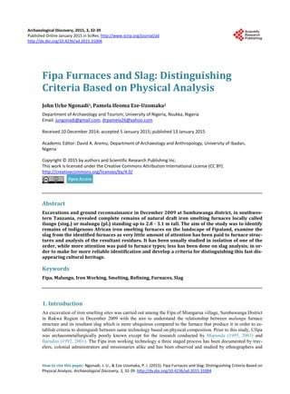
Three Malungu furnaces were identified with the kind assistance of Nzei Mlaya at Miangarua village in Mpui
Ward of Sumbawanga District (see Figure 1). Located on the plateau, two of these were complete while the
other furnace had disintegrated. These still standing iron smelting furnaces are about 2.75 - 3.09 m high. In Ku-
kumo village, at the escarpment, we located two still standing Malungu furnaces. The former is located on lati-
tude 08.40854˚S and longitude 031.66304˚E at an elevation of 1922 m above sea level and is 3.09 m high from
the ground surface with an exterior basal diameter of 5.60 m (Ngonadi, 2010, 2011). The latter in Itekesya (or
Itekesha) community is geographically situated within latitude 08.41816˚S and longitude 031.66953˚E, on an
elevation of 1931 m. This was 2.79 m high from the southern corner and 3.17 m from the northern corner with
an exterior basal diameter of 4.95 m. Each furnace had a peep-hole facing east, measuring 3 - 4.5 cm in diameter
with 10 tuyère ports. More so, two visible furnace remains were identified on the surrounding landscape. One
was the remains of kintengwe with evidence of flow slag littered around it (a miniature iron refining furnace)
Figure 1. Map of Sumbawanga district showing the study areas.
3. J. U. Ngonadi, P. I. Eze-Uzomaka
34
found in Vimbwa village (Figure 2). The geographical coordinates of this site which lies on the slope of a hill is
on latitude 08.39919˚S and longitude 031.66690˚E with a ground elevation of 1963 m above sea level. The other
was an Ilungu iron smelting furnace in Kukumo village which lies on latitude 08.40999˚S and longitude
031.66569˚E and on an elevation of 1927 m. Vimbwa refining furnace outcrop which was the first to be seen
and nearest to Miangarua furnace 1 is 5.62 km. Pottery and slag samples were collected from the surface for
identification and analysis, with the aim of understanding the technology and thereby opening up areas for fur-
ther research.
3. Description of Miangarua Site
The site is located on latitude 08.34880˚S and longitude 031.67115˚E and 4.47 km away from the nearest village,
Liapona and is 11.22 km away from Kaengesa Ward bus stand. The site lies on a low hill that forms part of the
foothill of the Sumbawanga folding mountains on Mr. Victor Kapusi’s farm. The slope of the site is to the north
in the direction of a stream, which is 155 m away. The site consists of great distribution quantities of iron slag,
tuyères and tuyère pieces, furnace fragments, two still standing furnaces, one collapsed furnace and other arc-
haeological materials. On the eastern corner of furnace #1, is a mound that was partly dug probably for the con-
struction of mud bricks. Where the furnace had collapsed the furnace base is surrounded by heaps of slag and
tuyère. Human settlement is sparse as four houses can be sited from the surroundings and the area is being ex-
ploited for agricultural and pastoral production. Iron smelting in this area must have been practiced on a full in-
dustrial scale to meet regional demands given the quantity and scatter of metallurgical debris in and around the
site. Surface collection of slag, tuyère fragments, daub and furnace wall debris was gathered, counted, weighed,
recorded and left behind.
Figure 2. Map of Miangarua site showing the contour lines and archaeologi-
cal features mentioned in the text.
4. J. U. Ngonadi, P. I. Eze-Uzomaka
35
4. Malungu Furnace Description
This was a tall, tapering, induced (natural) draught furnace called Ilungu (singular) Malungu (plural) in Swahili
(Figure 3). It measures 2.71 m from the eastern side and 2.41 m from the western side from ground to top but
measured 3.09 m after excavation. The difference in height can be due to soil deposition from the western corner
of the furnace as a result of erosion action or digging the mound close to the furnace for soil for construction of
mud bricks as evidenced in the vicinity. The outside diameter of the furnace from the southern tuyère port to the
northern tuyère port measures 170 cm. The exterior from the eastern tuyère port to the western tuyère port
measures 142 cm while the interior diameter of the furnace running from the southern tuyère port to the northern
tuyère port measures 142 cm and from the eastern to the western tuyère port, it measures 136 cm. The outside
circumference of the furnace above the tip of the tuyère openings measures 500 cm, 310 cm, 287 cm, 252 cm,
and 223 cm and then thins away to the tip measuring 170 cm. The width of the furnace wall from the broken part
on the northern corner measures 13 cm and thins out to the top. Some tuyères retrieved through excavation showed
heavy encrusting with vitreous slag both on the inside and the outside. This is an indication that the tuyères were
used for slag taping.
The exterior surface of the furnace was rough but it seemed like it was initially smoothened or plastered but
became worn-out with time. The furnace interior was highly vitrified or melted, and the walls also show signs of
superimposed rings of clay during construction. A hole popularly referred to as a peephole, which we disagree
with, given the temperature inside the furnace, measuring 103 - 111 cm from the ground surface was located on
the eastern corner of the furnace with an internal diameter of 7.2 cm. The furnace possesses 10 tuyère ports in-
tact with spacing between 27 and 37 cm. The height of the tuyère apertures ranges from 13 - 35 cm.
Figure 3. A view of the partly damaged Malungu furnace that was excavated.
Photo: Ngonadi John Uche (2010).
5. J. U. Ngonadi, P. I. Eze-Uzomaka
36
5. Excavation: Methods and Stratigraphy
A grid of 2 × 5 sq. m blocks was laid out over furnace #1. The inside and outside of the furnace was excavated
as sub-units. Excavation followed an arbitrary level of 5 cm in the interior of the furnace and 10 cm on the exte-
rior of the furnace. After leveling from surface to 35 cm given the deposition of furnace wall fragments in the
interior (F1#1), an arbitrary level of 5 cm was adopted and excavation continued to a depth of 70 cm. The sub-
datum point was established 50 cm from the southeastern peg of furnace 1 Unit 2 (F1#2) and was leveled from 0
cm - 70 cm given the sloping of the hill (Figure 4 shows a schematic description of the trench) and excavated at
an arbitrary level of 10 cm to a depth of 90 cm. Before excavation, the depths of the four coordinates of F1#2
are: NE—70 cm (08.34877˚S, 031.67117˚E), NW—70 cm (08.34873˚S, 031.67119˚E), SE—0 cm (08.34875˚S,
031.67124˚E), and SW—32 cm (08.34878˚S, 031.67116˚E). Given the fragile nature of the furnace, a 5 cm
amount of soil was left in and around the furnace to avoid collapsing. Evidence of iron slag was more pro-
nounced on the northwestern side of the furnace confirming the initial suggestion of slag tapping. The soils from
the excavation were screened using a 4.5 mm wire mesh to trap small archaeological materials such as slag
beads and the soil identified using a Munsell soil colour chart.
The interior (F1#1) of the furnace presented below showed interestingly an overlapping and interchangeable
soil colours and archaeological deposits.
Level 1: (0 - 35 cm) 2.5YR 4/6 Red, 7.5YR 5/8 Strong brown and 10YR 6/6 Brownish yellow. It produced
great number of charcoal and slag with little tuyère debris.
Level 2: (35 - 40 cm) 2.5YR 3/6 Dark red, 2.5YR 5/6 Light olive brown and 7.5YR 3/4 Dark brown. Two
holes became visible with lots of slag and charcoal.
Level 3: (40 - 45 cm) 10YR 5/2 Grayish brown, 10YR Light yellowish brown and 10YR 6/6 Brownish yellow.
Change in soil colour and decrease in tuyère fragments.
Level 4: (45 - 50 cm) 10YR 3/1 Very dark gray, 10YR 5/1 Gray, 10YR 5/2 Grayish brown and 10YR 6/8
Brownish yellow. The floor at this level was hard fired, compact and produced the highest number of slag.
Level 5: (50 - 55 cm) 2.5YR 4/6 Red and 10YR 5/2 Grayish brown. Presence of charred wood measuring 17
cm - 25 cm from the south, east and western corner of the furnace.
Level 6: (55 - 60 cm) 2.5YR 3/6 Dark red and 5YR 5/1 Gray. More logs of burnt wood in a bed-like position,
like a foundation.
Level 7: (60 - 65 cm) 5YR 4/4 Reddish brown. Decrease in slag, charcoal and charred wood.
Level 8: (65 - 70 cm) 2.5YR 4/6 Red. Change in soil colour and disappearance of cultural materials.
A wall profile (Figure 5) was drawn on the exterior (F1#2) of the furnace oriented on the southern wall run-
ning from SE-SW. The stratigraphic sequence contains tuyère fragments and slag and was made up of 4 layers
Figure 4. Schematic reconstruction of the Trench in Miangarua Site.
6. J. U. Ngonadi, P. I. Eze-Uzomaka
37
(see Figure 6). The first layer, the topsoil was grayish brown (10YR 5/2). The second layer was dark brown—
sandy clay (7.5YR 3/4) while the third layer was reddish brown-sandy silt (5YR 4/4). Finally, the fourth layer,
which was the sterile layer, was red in colour-sandy silt (2.5YR 4/6). The first three layers showed no natural
layering but were very disturbed by rootlets.
6. Discussion
The physical attributes examination of the iron smelting slag retrieved through excavation was done using Ma-
punda’s (2006) model with modifications. Slag with shared attributes were grouped as compound samples and
analyzed as one entity. The attributes are: volume (in cc), weight (in g), density (in g/cc), morphology/shape,
thermal condition, luster, porosity, magnetism, colour/streak, impression/inclusion, fragmentation, weathering,
raw material and surface condition. Together with volume, weight indicates the type of technological process
employed. Evidence shows that smelting slag is generally more massive and heavier than refining or smithing
slag. This is because the former contains more iron than the latter. Slag excavated from the furnace is smaller
and fist-sized chunks compared to the heavier chunks collected from the surface around the furnace, which is a
clear evidence of iron slag tapping technology. The volumes of the slag are expected from an iron smelting fur-
naces of this size and suggest the furnace reuse hypothesis. The thermal condition of the slag samples indicate a
Figure 5. The exterior of the excavated trench in Miangarua site (F1#2).
Photo: Ngonadi John Uche (2010).
Figure 6. Southern wall profile of F1#2, Miangarua Site.
7. J. U. Ngonadi, P. I. Eze-Uzomaka
38
high frequency of molten slag technology resulted from metallurgical processes as opposed to natural processes.
Four attributes were used to determine luster (ceramic, glass, metallic, greasy) and Malungu technology shows
high metallic luster and the frequency of porosity is nil. Magnetism reading was used to determine whether the
slag is ferrous or nonferrous and efficiency of the reduction technique—the higher the magnetic attraction the
higher the content of iron (whether metallic or oxide) present in the slag and vice versa. The iron slag possess
low rate of magnetism, which indicates efficient smelting technology practiced on the plateau. Malungu furnaces are
constructed using tertiary clay, sited very far from residential area and are not more than 300m away from a wa-
ter source.
A total of 1157 complete tuyères (measuring 18 - 22 cm) and tuyère fragments were retrieved with smooth
surfaces, clay texture and sand as the tempering material (for summary see Table 1). The internal diameter
ranges from 3.4 - 4.2 cm and the external diameter are 6.1 - 7.6 cm with a thickness of 2 - 2.9 cm. Tuyère from
this technology has heavy slag coating. A good quantity of charcoal and bark wood strips from minute particles
to pieces measuring 17 - 25 cm at the base of the furnace was noted. These wooden strips are ritual medicine,
vizimba, made at the center of Malungu furnaces to ensure the success of the smelt. Sometimes it is to protect
against otherwise uncontrollable, sinister forces that might harm the smelt (Schmidt & Avery, 1983, Davison &
Mosley, 1988). Small pieces of stone and two hammer stones were excavated. This and other abraded stones
might have been used during ore preparation and later after smelt, discarded and thrown into the furnace (Ma-
punda pers. comm. 2010) as against being a Later Stone Age material. The potsherds retrieved from excavation
are burnished body sherds that seem to represent only a few vessels, presumably vessels used by the smelters for
storing water and food.
7. Conclusion
The method used in arriving at the results of this investigation is based on physical observation that is usually a
researcher’s first line of judgment in the field before the choice of laboratory re-examination is conducted. The
results for this study reveal that the Fipa used two different clay colour, reddish brown and dark brown and two
different furnace morphology. As mentioned above, Malungu furnaces are sited very far from residential areas
for security and concentration among the smelters in order to avoid distraction of any sort, be it sexual or family
responsibility, as their energy is important for the success of the smelt. Since one of the purposes of excavation
was to examine the furnace interior, learn about the height, deposition of metallurgical materials and the type of
ritual practices obtainable. The furnace interior shows rings of slag encrusting evidence of furnace reuse. The
slag from this study shows that Malungu produced heavy and very big slag with evidence of flow marks and a
high frequency of metallic luster. It also has a low rate of magnetism; an indication that the smelting technology
employed can correctly be rated as efficient. Vizimba was identified at center of the furnace interior at levels 50 - 60
cm—showing evidence of ritual practice. Ethnographic and archaeological studies indicate that medicines were
used almost universally to ensure the success of smelting. In most cases, usually these were organic materials,
each ingredient perhaps symbolizing some property to be transferred to the firing process or the product (Davi-
son & Mosley, 1988).
It has been argued (Humphris et al., 2007) that the slag deposited on the landscape as well as its contents is
not necessarily based on the composition of its formation processes in the furnace but based on human decisions.
Such choices during smelting processes or pattern include the inclusion of fluxing materials, which may have
Table 1. Summary of materials recovered and their weights.
Slag Slagy Tuyère
Tuyère/
Tuyère
Fragments
Charcoal/
Burnt Wood
Furnace Wall
Debris
Lithics Potsherds Daub
Surface
Collection
1781 215 441 0 42 0 4 0
Furnace Interior
(F1#2)
3023 32 52 997 119 8 3 9
Furnace
Exterior (F1#2)
1175 66 351 0 9 4 6 15
Weight (kg) 661.9 225.6 32.3 3 471.2 5 - -
8. J. U. Ngonadi, P. I. Eze-Uzomaka
39
had indirect contribution to the formation of the resultant slag. The degree of reduction is a function of fuel-to-
ore ratios and airflow through the furnace; both parameters are directly controlled first by the furnace design,
and then the head smelter during the smelt, etc. Similarly, the addition of quartz sand as a flux in smelting ex-
tremely rich magnetite ore must have evolved in some way.
Acknowledgements
The material published in this paper formed part of a Master of Arts dissertation submitted in partial fulfillment
of the requirements of the degree of MA in Archaeology at the University of Dar es Salaam funded by SIDA/
SAREC through African Archaeology Network. The authors are grateful to Professor Bertram Mapunda and
Professor Felix Chami for their various contributions.
References
Barndon, R. (2001). Masters of Metallurgy-Masters of Metaphors: Ironworking among the Fipa and Pangwa of Southwestern
Tanzania. Bergen: University of Bergen.
Childs, S. T. (1991). Style, Technology and Iron-Smelting Furnaces in Bantu Speaking Africa. Anthropological Archaeology,
10, 332-359. http://dx.doi.org/10.1016/0278-4165(91)90006-J
Davison, S., & Mosley, P. N. (1988). Iron-Smelting in the Upper North Rukuru Basin of Northern Malawi. Azania, 23, 57-
99. http://dx.doi.org/10.1080/00672708809511387
Greig, R. C. H. (1937). Iron Smelting in Fipa. Tanganyika Notes and Records, 4, 77-81.
Humphris, J. E., Rehren, T., Charlton, M., Chirikure, S., Ige, A., & Veldhuijzen, H. A. (2007). Decisions Set in Slag: The
Human Factor in African Iron Smelting. Metals and Mines: Archaeometallurgy, 211-218.
Kense, F. J. (1983). Traditional African Iron Working. Calgary: University of Calgary.
Lechaptois, M. (1913). Aux Rives Du Tanganyika. Algiers: Maison-Carée.
Mapunda, B. B. B. (1995). An Archaeological View of the History and Variation of Ironworking in Southwestern Tanzania.
Ph.D. Thesis, Florida: University of Florida.
Mapunda, B. B. B. (2003). Fipa Iron Technologies and Their Implied Social History. In C. M. Kusimba, & S. B. Kusimba
(Eds.), East African Archaeology: Foragers, Potters, Smiths and Traders. Pennsylvania: University of Pennsylvania Mu-
seum. http://dx.doi.org/10.9783/9781934536261.71
Mapunda, B. B. B., (2010). Contemplating the Fipa Iron Working. Kampala: Fountain Publishers.
Ngonadi, J. U. (2010). Relationship between Furnace Structure and Slag Properties: The Case of Fipa and Nyiha Iron
Smelting Technology. MA Dissertation, Dar es Salaam: University of Dar es Salaam.
Robert, J. M. (1949). Croyances et coutumes magico—Religieuses des Wafipa païens. Tabora: Tanganyika Mission Press.
Schmidt, P. R., & Avery, D. H. (1983). More Evidence for an Advanced Prehistoric Iron Technology in Africa. Field Arc-
haeology, 10, 421-434. http://dx.doi.org/10.1179/009346983791504228
Wembah-Rashid, J. (1969). Iron Workers of Ufipa. Bulletin of International Committee of Urgent Anthropological Research,
11, 65-72.
Willis, R. G. (1966). The Fipa and Related Peoples of Southwest Tanzania and Northeast Zambia. London: International
African Institute.
Willis, R. G. (1981). A State in the Making: Myth, History, and Social Transformation in Precolonial Ufipa. Bloomington:
Indiana University Press.
Wise, R. (1958a). Iron Smelting in Ufipa. Tanganyika Notes and Records, 50, 106-111.
Wise, R. (1958b). Some Rituals of Iron—Making in Ufipa. Tanganyika Notes and Records, 51, 232-238.
Wyckaert, A. (1914). Forgerons Païens et Forgerons Chrétiens Au Tanganyika. Anthropos, 9, 371-380.